HP HPJ4116A User manual

1
HP ProCurve Switch
Gigabit Stacking Kit Installation Guide
Introduction
The HP ProCurve Switch Gigabit Stacking Kit (HP J4116A) is used to provide
a 1000 Mbps stacking connection between any two HP ProCurve switches
that support the kit. The kit consists of two HP ProCurve Gigabit Stacking
Transceivers and a 0.5-meter shielded twisted-pair Stacking Cable.
Install each of the transceivers in the kit into either one of the transceiver
slots of two HP ProCurve Switch 2424M Gigabit Stacking Modules
(HP J4130A) or a transceiver slot in any other HP ProCurve switch that
supports these transceivers. If you are using the Gigabit Stacking Module,
the module is then installed into the module slot of an HP ProCurve Switch
2424M that you want to stack. The Gigabit Stacking Transceivers installed
in modules, or directly in switches, are then connected through the Stacking
Cable supplied in the kit as shown in the illustration below.
To connect another switch to these two requires another Gigabit Stacking
Kit.
HP ProCurve Switch Gigabit Stacking Kit
j4116101.fm Page 1 Tuesday, October 3, 2000 5:29 PM

2
This document describes how to install, verify, and troubleshoot the HP
ProCurve Switch Gigabit Stacking Kit.
Installation Notes:
Please read these notes before proceeding.
■The illustrations in this document show the HP ProCurve Gigabit
Stacking Transceivers being used in a small number of the HP
networking devices that are designed to accept them. But, the
procedures pertain to using these transceivers in all the HP
networking devices that accept them.
As of this printing, the following HP ProCurve switches support the
Gigabit Stacking Kit:
• HP ProCurve Switch 2424M (by using a Gigabit Stacking Module
with the switch)
• HP ProCurve Series 2300 Switches (2312 and 2324)
• HP ProCurve Series 2500 Switches (2512 and 2524)
■For all of the networking devices that support the Gigabit Stacking
Transceivers, it is not necessary to turn off power to the device
before installing the transceiver into it:
• For the Switch 2424M Gigabit Stacking Module, you can leave
the power on to the switch, but to avoid possible damage to the
transceiver circuitry, remove the Gigabit Stacking Module from
the switch before installing transceivers into it, or unplug the
power from the Switch 2424M. Please see the Switch 2424M
Gigabit Stacking Module Installation Guide (J4130-90001) for
more information. Reinstalling the module into the switch
initializes and activates the transceivers.
• For the Series 2300 and 2500 Switches, you can install the
transceivers while the switches are powered on, but you must
reset or reboot the switch after installing the transceiver to
initialize and activate it.
j4116101.fm Page 2 Tuesday, October 3, 2000 5:29 PM

3
Installation Steps
To install the HP Gigabit Stacking Kit, follow these steps:
1. Follow anti-static precautions when handling the Stacking
Transceivers and Switch 2424M Gigabit Stacking Module (if
used). When handling the transceivers (and module) and installing
them in your switch, follow these procedures to avoid damage from
static electricity:
• Handle the transceivers (and module) by their bulkheads or edges
and avoid touching the components and the circuitry on the boards.
• When installing the transceivers (and module), equalize any static
charge difference between your body and the switch by wearing a
grounding wrist strap and attaching it to the switch’s metal body, or
by frequently touching the switch’s metal body.
2. If the Gigabit Stacking Transceiver is being installed in a Switch 2424M
Gigabit Stacking Module, first remove the module from the Switch
2424M, or unplug the Switch 2424M from the AC power source.
3. Using a flat-bladed or Torx
T-10 screwdriver, unscrew
the two retaining screws
on the slot cover plate or
existing transceiver, and
remove it from the module
or switch. Keep the cover
plate for future use—unused transceiver slots should be kept covered
for proper switch operation.
4. Slide the transceiver firmly
into the transceiver slot as
far as it will go. The trans-
ceiver will “snap” into
place, and the transceiver's
faceplate should touch the
face of the module.
5. Using the flat-bladed or Torx T-10 screwdriver, tighten the retaining
screws on the transceiver until they are secure, but be careful that you
do not overtighten the screws.
loosen these screws and remove the cover plate
slidethetransceiver
into the slot until it
snaps into place
j4116101.fm Page 3 Tuesday, October 3, 2000 5:29 PM

4
6. If the transceiver has been installed in a Switch 2424M Gigabit Stacking
Module, reinstall the module into the Switch 2424M and make sure the
switch is powered on, or simply power on the switch if you did not
remove the module.
For the Series 2300 and 2500 Switches, reset or reboot the switch to
initialize and activate the transceiver. (Until the Series 2300 or 2500
Switch is reset or rebooted, the Link LED for the transceiver port will
flash indicating that the transceiver is not yet initialized.)
7. Check the switch or module LEDs associated with the transceiver to
verify that the transceiver has been installed correctly.
For the Gigabit Stacking Module, the
Link and Mode LEDs come on briefly
as the transceiver port is self tested.
For the Series 2300 and 2500
Switches, the Link LED for
the transceiver port stays
off.
When the transceiver self test completes, the LEDs go off until a
stacking cable is plugged in to the port, as described in the next section.
If the LED pattern is different that what is described above, especially
if the transceiver Link LED and the switch Fault LED blink simulta-
neously, please see the “Troubleshooting” section on page 6.
Link LED
Mode LED
transceiverport
Link LED
j4116101.fm Page 4 Tuesday, October 3, 2000 5:29 PM

5
Connect the Stacking Cable to the Transceiver Ports
To connect the 0.5-meter Stacking Cable to the trans-
ceiver:
1. Press the cable connector into the transceiver
jack so that the connector snaps securely into
place.
2. Repeat for the Stacking Transceiver in the other
switch at the other end of the cable.
Note: If you need a longer stacking connection, a
10-meter cable has also been tested and verified.
The cable is AMP part number 1-1324640-0.
As shown in the next illustration, either or both of the transceiver slots in a
Gigabit Stacking Module or switch can be used for a stacking connection.
The switches at the top and bottom of the stack will have an unused
transceiver slot that can be used for connections to other devices.
Stacking connections between
switches.
Note that any transceiver slot can
be used for a stacking connection.
Each stacking connection requires
one Gigabit Stacking Kit
Gigabit-LXor-SXconnection
to campus backbone, other
switches in a remote
location, or a local server
j4116101.fm Page 5 Tuesday, October 3, 2000 5:29 PM

6
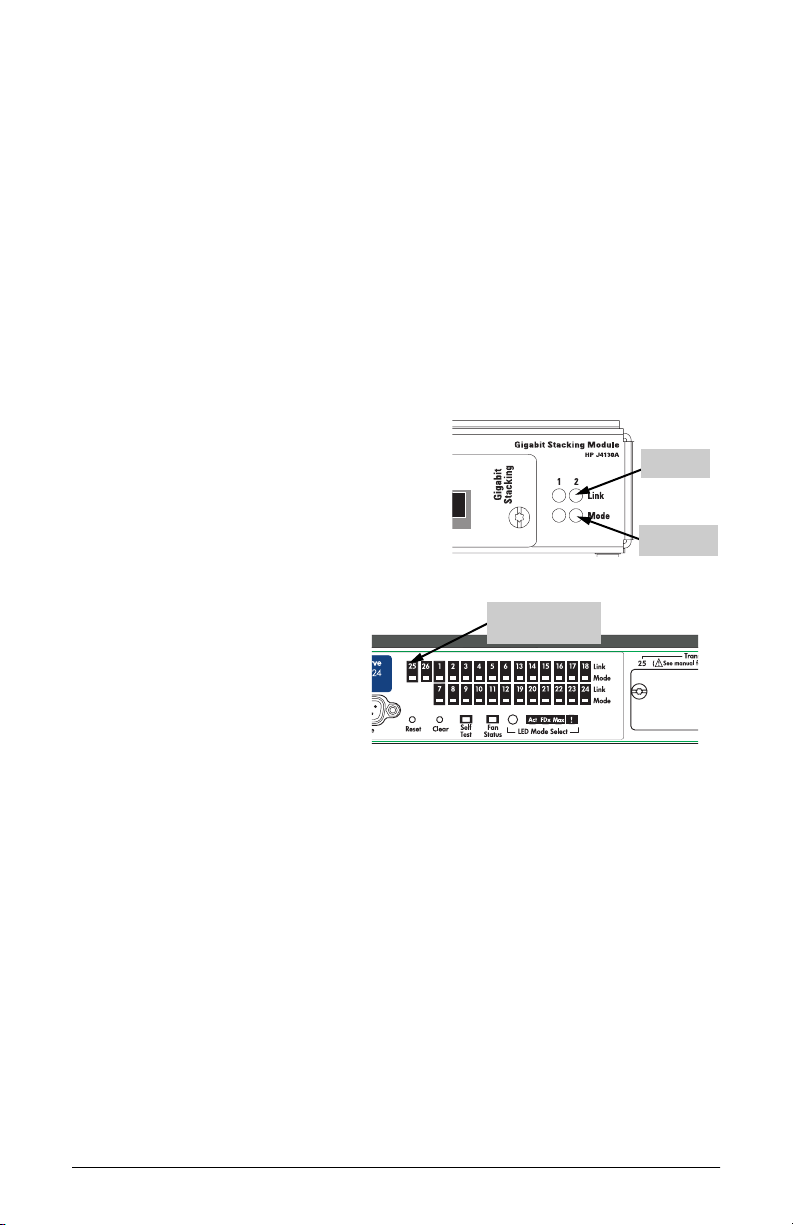
3. When the transceiver is receiving
power and the stacking cable is
connected to another active switch,
the Link LED for the transceiver port
should be ON.
If the Link LED is off, see “Trouble-
shooting”, below.
Troubleshooting
The following indications may occur:
■The Link LED for the transceiver is not on, even though the transceiver
is receiving power and the stacking cable is connected. Check the
following:
• Verify that both of the connected switches are powered on.
• Check the stacking cable and connections to make sure that the connec-
tions are secure, neither connector is damaged, and that none of the
connectors have a dust buildup or other object in the way that may cause
interference to the connection. If all connections are OK, try a different
cable.
• Try resetting or cycling power (turn the power off and then back on) on
the switch that is having the problem. If the transceiver was installed into
a Gigabit Stacking Module that was “hot swapped” into the Switch 2424M,
the resulting hot-swap self test does not test the transceivers. Resetting the
switch causes a complete self test to be performed, which does test the
transceivers.
■The switch Link LED for the transceiver port is flashing. This condi-
tion occurs on the Series 2300 and 2500 Switches. After installing the
transceiver, these switches must be reset or rebooted to initialize the
transceiver. The flashing LED tells you that the transceiver is not operational
until the switch is reset or rebooted.
■The switch Fault LED and Link LED for the transceiver port are
flashing. The transceiver may not be installed correctly, or it may be faulty.
Disconnect power to the switch and reinstall the transceiver into the
module or switch. Verify the transceiver screws are tightened securely.
Reconnect power to the switch back on, and if the flashing persists, the
transceiver may be faulty.
For additional troubleshooting, see the HP ProCurve Switch 2424M Gigabit
Stacking Module Installation Guide (J4130-90001) or the HP ProCurve Series 2300
and 2500 Switches Installation and Getting Started Guide (5969-2353). For the
managed switches, you can also use the switch's console interface, the switch’s web
browser interface, or HP TopTools for Hubs & Switches to troubleshoot and
configure the Gigabit transceiver port. See the switch's Management and Configu-
ration Guide for more information.
Link LED
j4116101.fm Page 6 Tuesday, October 3, 2000 5:29 PM

7
Customer Support Services
If you are having any trouble with your Gigabit Stacking Kit,
Hewlett-Packard offers support 24 hours a day, seven days a week through
the use of a number of automated electronic services. See the Customer
Support/Warranty booklet that came with your Gigabit Stacking Kit for
information on how to use these services to get technical support.
The HP networking products World Wide Web site, http://www.hp.com/go/
hpprocurve also provides up-to-date support information and contact
phone numbers. Click on the Technical Support link on that web page.
Additionally, your HP-authorized network reseller can provide you with
assistance, both with services that they offer and with services offered by
HP.
Gigabit Stacking Transceiver Specifications
Environmental
Electromagnetic Emissions
FCC part 15 Class A
EN55022 / CISPR-22 Class A
VCCI Class A
Complies with Canadian EMC Class A requirements
The Gigabit Stacking Kit is designed for operation with the HP ProCurve
Switch 2424M and the HP ProCurve Series 2300 and 2500 Switches. The kit
components are listed in the Declaration of Conformity for those switches.
Contact your HP-authorized dealer or reseller if you need information about
the declaration.
Operating Non-Operating
Temperature: 0°C to 55°C (32°F to 131°F) -40°C to 70°C (-40°F to 158°F)
Relative humidity:
(non-condensing)
15% to 95% at 40°C (104°F) 15% to 90% at 65°C (149°F)
Maximum altitude: 4.6 km (15,000 ft) 4.6 km (15,000 ft)
j4116101.fm Page 7 Tuesday, October 3, 2000 5:29 PM

Technical information in this document is
subject to change without notice.
ãCopyright Hewlett-Packard Company, 2000.
All rights reserved. Reproduction, adaptation,
or translation without prior written permission
is prohibited except as allowed under the
copyright laws.
Printed in Singapore 10/2000
Manual Part Number
J4116-90101
*J4116-90101*
j4116101.fm Page 8 Tuesday, October 3, 2000 5:29 PM
Table of contents
Other HP Cables And Connectors manuals

HP
HP 537601-001 User manual

HP
HP StorageWorks P2000 User manual

HP
HP 16089A Operation manual

HP
HP 11667B Service manual

HP
HP G7U78AA User instructions

HP
HP USB Type-C Quick reference guide

HP
HP Xw4600 - Workstation - 2 GB RAM Instruction sheet

HP
HP A3352A - 4 GB Hard Drive User manual

HP
HP StorageWorks SN6000 User manual

HP
HP E5346A Quick start guide