manuals.online logo
Brands
  1. Home
  2. •
  3. Brands
  4. •
  5. HP
  6. •
  7. Copier
  8. •
  9. HP Designjet cc800ps User manual

HP Designjet cc800ps User manual

1
123
456
system recovery
cd-rom
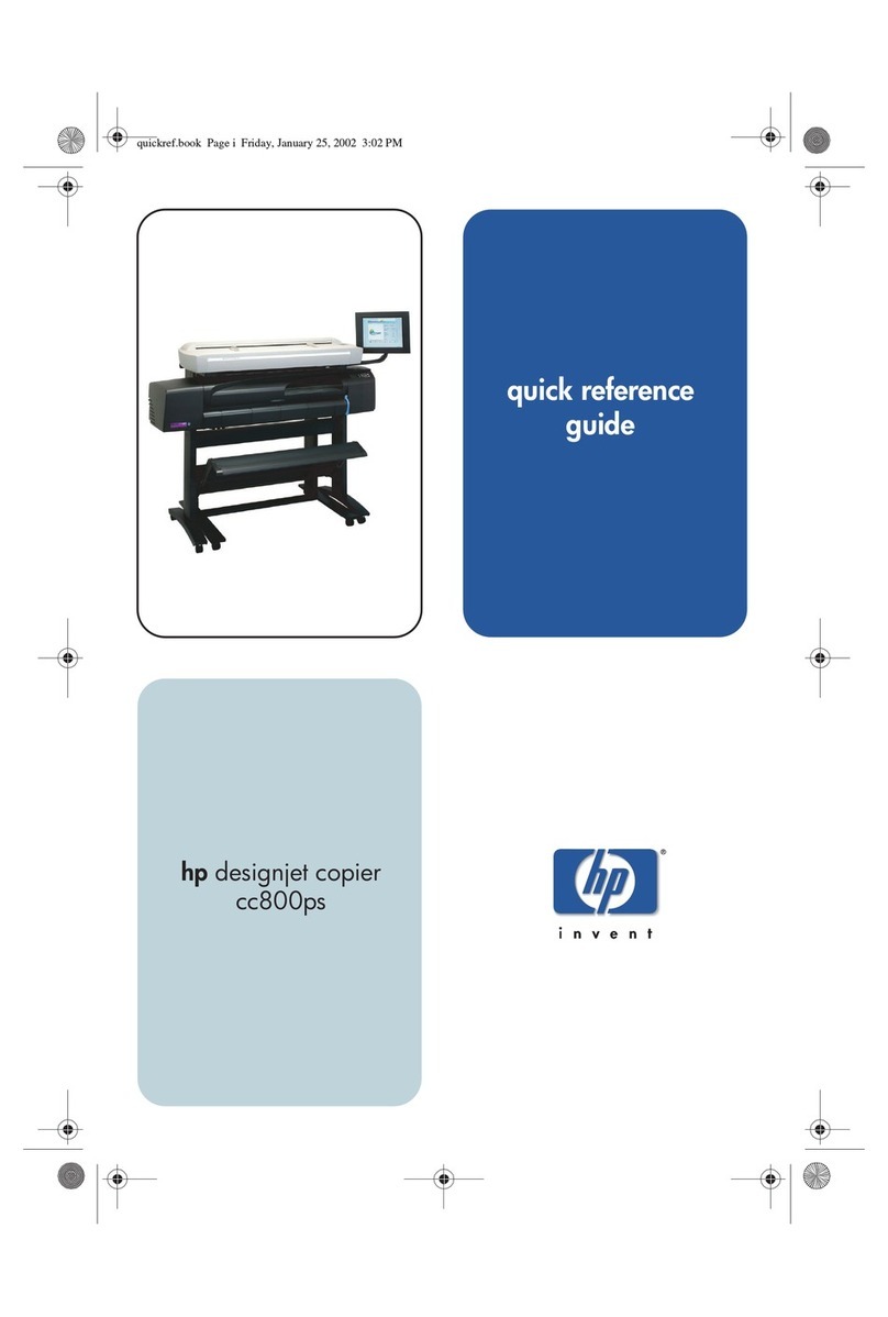
hp designjet copier
cc800ps
hp designjet copier cc800ps
Your printer
should already be
assembled and working be ore starting this
procedure. For instructions on how to
assemble the printer, please re er to the
assembly poster included with the printer.
Read these instructions carefully...
and complete each stage be ore you start the
next.
What You Will Need to Do the Job
Because some o the components o the copier
are bulky, you will need 2 or 3 people to li t
them. See the descriptions that ollow or
details, a symbol like this is used:
A note about fixings
When initially assembling the copier stand
do not ully tighten the screws; you will be
asked to do this later.
Raise the
legs care ully
into the
upright position.
Attach the bottom bar to the other leg using 2
M6X10 screws.
Attach the
bottom bar to
the leg using 2
M6X10 screws.
Lay the 2 legs
down into the
position shown.
Secure the 2
legs by
astening the cross
bar with 4 M6X10 screws (2 each side).
Attach the 2 eet
to the le t and right
legs using 4
M6x30 screws (2
or each oot), tighten the screws with the Allen
key ound in the assembly kit.
Assembly poster
2 Scanner
3 Rear Table
4 Top bar
with guide
5 Leg (x2)
12 Foot (x2) 13 Scanner
maintenance
sheet
14 Front panel arm
11 USB cables
8 Power
cables
16 Front
panel
15 Touch
screen
stylus
18 System recovery
cd-rom
10 Bottom bar
7 Assembly
kit
Assembly kit contents
Description Quantity
Screw M6X10 or base and top bar 10
Screw M6X30 or base and top bar 8
Screw M4X25 or ront panel arm 4
Allen Key 2,5mm or ront panel 1
Screw M4X8 or ront panel 5
Slotted special screw or scanner 4
Allen Key 5mm or Top Bar 1
Allen Key ront panel arm 1
6 Maintenance
kit
1 Plastic dust
cover
9 Cross bar
17 Media guides (x2)
hp designjet copier cc800ps
Assembly Instructions
89
7
15
14
16 17
20
19
11 12
13
2
10
18
hp designjet copier cc800ps
E
X
T
E
N
D
E
D
E
X
I
T
E
X
I
T
N
O
R
M
A
L
E
X
T
E
N
D
E
D
N
O
R
M
A
L
Inchesmm
0.63
0.55
0.47
0.39
0.31
0.24
0.16
0.08
16
14
12
10
8
6
4
2
E
X
T
E
N
D
E
D
E
X
I
T
E
X
I
T
N
O
R
M
A
L
E
X
T
E
N
D
E
D
N
O
R
M
A
L
Inchesmm
0.63
0.55
0.47
0.39
0.31
0.24
0.16
0.08
16
14
12
10
8
6
4
2
E
X
T
E
N
D
E
D
E
X
I
T
E
X
I
T
N
O
R
M
A
L
E
X
T
E
N
D
E
D
N
O
R
M
A
L
Inches mm
0.63
0.55
0.47
0.39
0.31
0.24
0.16
0.08
16
14
12
10
8
6
4
2
E
X
T
E
N
D
E
D
E
X
I
T
E
X
I
T
N
O
R
M
A
L
E
X
T
E
N
D
E
D
N
O
R
M
A
L
Inchesmm
0.63
0.55
0.47
0.39
0.31
0.24
0.16
0.08
16
14
12
10
8
6
4
2
E
X
T
E
N
D
E
D
E
X
I
T
E
X
I
T
N
O
R
M
A
L
E
X
T
E
N
D
E
D
N
O
R
M
A
L
Inchesmm
0.63
0.55
0.47
0.39
0.31
0.24
0.16
0.08
16
14
12
10
8
6
4
2
E
X
T
E
N
D
E
D
E
X
I
T
E
X
I
T
N
O
R
M
A
L
E
X
T
E
N
D
E
D
N
O
R
M
A
L
Inchesmm
0.63
0.55
0.47
0.39
0.31
0.24
0.16
0.08
16
14
12
10
8
6
4
2
E
Position your fingers in the 4 lock slots (2 t
e ch end of the pl ten indic ted by the green
rrows bove), nd press down (blue rrows).
With the pl ten pushed down, slide the 2
locks inw rds until the pins t either end pop
up locking the pl ten open nd re dy to be
removed.
F sten the top b r nd wire guide to the 2 legs
using 4 M6X30 nd 2 M6X10 screws.
Connect the re r t ble: this is fitted by
loc ting the 4 guide pins on the re r of the
t ble into the rubber fr med holes on the top
b r.
Att ch the front p nel rm by sliding the rm's
mount onto the top b r, ligning the holes,
nd fixing lightly with 2 M4X25 screws. Lift the front p nel rm nd tighten the 2
finger screws. Tighten the 2 M4X25 screws firmly.
Lift the sc nner into pl ce, loc ting the rubber
feet in the holes indic ted, nd fixing with the
4 slotted speci l screws.
Rest the front p nel onto
the n rrow shelf nd
tt ch with 2 M4X8 screws where shown.
N rrow shelf
Cleaning the Scan Area...
You re now required to cle n the sc n
re , to do so you will need the cle ning
tools provided in the m inten nce kit nd
cle ning fluid (not included in the
m inten nce kit).
Caution: do not use br sives,
cetone, benzene or fluids th t cont in
these chemic ls. Do not spr y liquids
directly onto the sc nner gl ss pl te or
nywhere else in the sc nner.
Att ch with 3 more M4X8 screws s shown.
Slide the
ssembled printer
under the designjet
copier. The printer's
st nd feet will be positioned on the outer sides
of the copier's. The unit is now ssembled nd should ppe r
like the bove illustr tion.
Open the sc nner cover to expose the sc n
re .
Take care when tightening as this
item can slip.
M6X30
M6X10
Remove the pl stic s fety tie nd tighten up ll
screws firmly.
Front
p nel
rm
Tighten (X2)
23
22
28 29
31
30
32 33 34
26
27
3
25
24
21
E
X
T
E
N
D
E
D
E
X
I
T
E
X
I
T
N
O
R
M
A
L
E
X
T
E
N
D
E
D
N
O
R
M
A
L
Inchesmm
0.63
0.55
0.47
0.39
0.31
0.24
0.16
0.08
16
14
12
10
8
6
4
2
E
X
T
E
N
D
E
D
E
X
I
T
E
X
I
T
N
O
R
M
A
L
E
X
T
E
N
D
E
D
N
O
R
M
A
L
Inchesmm
0.63
0.55
0.47
0.39
0.31
0.24
0.16
0.08
16
14
12
10
8
6
4
2
E
X
T
E
N
D
E
D
E
X
I
T
E
X
I
T
N
O
R
M
A
L
E
X
T
E
N
D
E
D
N
O
R
M
A
L
Inchesmm
0.63
0.55
0.47
0.39
0.31
0.24
0.16
0.08
16
14
12
10
8
6
4
2
E
X
T
E
N
D
E
D
E
X
I
T
E
X
I
T
N
O
R
M
A
L
E
X
T
E
N
D
E
D
N
O
R
M
A
L
Inchesmm
0.63
0.55
0.47
0.39
0.31
0.24
0.16
0.08
16
14
12
10
8
6
4
2
E
X
T
E
N
D
E
D
E
X
I
T
E
X
I
T
N
O
R
M
A
L
E
X
T
E
N
D
E
D
N
O
R
M
A
L
Inchesmm
0.63
0.55
0.47
0.39
0.31
0.24
0.16
0.08
16
14
12
10
8
6
4
2
E
X
T
E
N
D
E
D
E
X
I
T
E
X
I
T
N
O
R
M
A
L
E
X
T
E
N
D
E
D
N
O
R
M
A
L
Inchesmm
0.63
0.55
0.47
0.39
0.31
0.24
0.16
0.08
16
14
12
10
8
6
4
2
hp designjet copier cc800ps
E
X
T
E
X
T
E
N
D
E
D
E
X
I
T
E
X
I
T
N
O
R
M
A
L
E
X
T
E
N
D
E
D
N
O
R
M
A
L
Inchesmm
0.63
0.55
0.47
0.39
0.31
0.24
0.16
0.08
16
14
12
10
8
6
4
2
E
X
T
E
N
D
E
D
E
X
I
T
E
X
I
T
N
O
R
M
A
L
E
X
T
E
N
D
E
D
N
O
R
M
A
L
Inches mm
0.63
0.55
0.47
0.39
0.31
0.24
0.16
0.08
16
14
12
10
8
6
4
2
E
X
T
E
X
T
E
N
D
E
D
E
X
I
T
E
X
I
T
N
O
R
M
A
L
E
X
T
E
N
D
E
D
N
O
R
M
A
L
Inchesmm
0.63
0.55
0.47
0.39
0.31
0.24
0.16
0.08
16
14
12
10
8
6
4
2
E
X
T
E
N
D
E
D
E
X
I
T
E
X
I
T
N
O
R
M
A
L
E
X
T
E
N
D
E
D
N
O
R
M
A
L
Inchesmm
0.63
0.55
0.47
0.39
0.31
0.24
0.16
0.08
16
14
12
10
8
6
4
2
E
X
T
E
N
D
E
D
E
X
I
T
E
X
I
T
N
O
R
M
A
L
E
X
T
E
N
D
E
D
N
O
R
M
A
L
Inchesmm
0.63
0.55
0.47
0.39
0.31
0.24
0.16
0.08
16
14
12
10
8
6
4
2
E
X
T
E
N
D
E
D
E
X
I
T
E
X
I
T
N
O
R
M
A
L
E
X
T
E
N
D
E
D
N
O
R
M
A
L
Inchesmm
0.63
0.55
0.47
0.39
0.31
0.24
0.16
0.08
16
14
12
10
8
6
4
2
Clean the glass with a lint-free cloth and a mild
streak-free glass cleaner.
Dry the glass fully using a separate clean dry
lint-free cloth like the one provided with the
maintenance kit.
Raise the two handles and remove the
pressure platen.
Turn the pressure platen over to expose the
white background plate. Clean the white background plate with a lint-
free cloth and a mild streak-free glass cleaner.
Clean the transport rollers and surrounding
area.
Dry the white background plate rollers and
surrounding area fully using a separate clean
dry lint-free cloth.
Keep out dust and reduce maintenance
time...
Cover your scanner with the plastic dust
cover when not in use.
Caution:
make sure the scanner
power is OFF when using the scanner
dust cover.
Replace the pressure platen and lower the two
handles. Pushing downwards on the left side of the
pressure platen; push in the pin (a) and slide in
the lock (b) locking the platen end into place.
With the platen firmly locked into place; close
the scanner cover.
Connect the front panel to the scanner using
the shorter USB cable and fastening with the
clips where shown (the clips are on the inside
of the arm).
Peel away the protective paper from the front
panel stylus (a) and stick to the side of the
front panel where shown (b).
Connect a power cable to the front panel and
a power outlet.
a
Caution: see note after step 17
a
a
b
ab
ab
Pushing downwards on the right side of the
pressure platen; push in the pin (a) and slide in
the lock (b) locking the platen end into place.
ab
37
4
41
35
40 41
45
43
44
42
36
39
38
Connect the other power cable to the scanner.
Connect the scanner's power cable to a
power outlet.
Camera alignment & calibration...
(Hei ht ali nment, stitchin , basic
calibration and color calibration)
You are now required to calibrate the
scanner, for this you will need the scanner
maintenance sheet, found in the protective
folder shown below.
If not done so already, connect the printer to a
power outlet and switch it on.
Important: make sure that the
copier is turned on for at least one hour
prior to movin on to the next step of
camera ali nment calibration. Sli ht
li ht intensity chan es and camera
shiftin can occur just after turnin the
scanner on and warm-up time will
ensure that li ht conditions and camera
hei hts have stabilized.
1 hour
Note: if on switchin on the front panel a
'not present' messa e appears, please
press the 'Rescan' option on the front
panel.
Connect the front panel to the printer usin the
lon er USB cable and fastenin with the clips
where shown (you must lift the rear table to
access some of the clips).
Switch on the scanner and leave it to warm up
for some minutes until the reen (ready status)
li ht appears.
When the reen (ready status) li ht has
appeared, switch on the front panel.
To start the maintenance procedure:
a) on the front panel menu press the setup tab
b) press the scanner button
c) press the scanner maintenance button
(shown above).
Ready status li ht
The maintenance wizard will ask you to insert
the maintenance sheet. The sheet's printed
side must be face down. Feed the paper in
ali nin the two midpoint arrows. Press 'Next'
to continue.
Now follow the instructions that appear on the
front panel.
When calibration completes the maintenance
process; remove the scanner maintenance
sheet and return it to its protective cover. Store
the folder in a dry place away from li ht.
Note: Your copier is now ready for use,
please make sure that the printer is loaded
with media and inks ready for use.
When System Administrators confi ure your
system in a network domain, they will also
need to setup automatic lo in. This procedure
is documented in 'how do I setup automatic
lo in' in your online help.
Adjust the USB cable to leave enou h slack to
be able to pull out the printer when chan in
paper.
Slack
5
E
X
T
E
N
D
E
D
E
X
I
T
E
X
I
T
N
O
R
M
A
L
E
X
T
E
N
D
E
D
N
O
R
M
A
L
Inchesmm
0.63
0.55
0.47
0.39
0.31
0.24
0.16
0.08
16
14
12
10
8
6
4
2
8786 85 8483
94 93 92
92 9190 89 88
97
93
98
96 95
0
40
Inches
Inches
The copier's measure can be changed
between centimeters and inches b sliding
it out, turning it over and reinserting it.
The copier comes equipped with 2
magnetic media guides: these can be
placed, and moved as required.
For an further information on how to use
our copier, see the online help s stem
available on our front panel using the button
below.
6
Not for resale
©2002 Hewlett-Packard Company
All rights reserved
ade in Europe
Q1262-90011

Other manuals for Designjet cc800ps

2

Other HP Copier manuals

HP LaserJet Enterprise M601 Series User manual

HP

HP LaserJet Enterprise M601 Series User manual

HP CM8060 Color MFP User manual

HP

HP CM8060 Color MFP User manual

HP C5370A User manual

HP

HP C5370A User manual

HP 210/210LX User manual

HP

HP 210/210LX User manual

HP Compaq 610 How to use

HP

HP Compaq 610 How to use

HP ProSignia 310 User guide

HP

HP ProSignia 310 User guide

HP Designjet cc800ps User manual

HP

HP Designjet cc800ps User manual

HP Compaq 610 User manual

HP

HP Compaq 610 User manual

HP Designjet 5500mfp User manual

HP

HP Designjet 5500mfp User manual

HP ProSignia 310 User manual

HP

HP ProSignia 310 User manual

HP LASERJET ENTERPRISE MFP M725dn Programming manual

HP

HP LASERJET ENTERPRISE MFP M725dn Programming manual

HP Compaq 610 Configuration guide

HP

HP Compaq 610 Configuration guide

HP Designjet cc800ps User manual

HP

HP Designjet cc800ps User manual

HP Designjet 110 - Color Printer User guide

HP

HP Designjet 110 - Color Printer User guide

Popular Copier manuals by other brands

Kyocera KM-2540 Service manual

Kyocera

Kyocera KM-2540 Service manual

Xerox DocuColor 30 Settings guide

Xerox

Xerox DocuColor 30 Settings guide

Ricoh FT4480 Field service manual

Ricoh

Ricoh FT4480 Field service manual

Konica Minolta bizhub 350 How to use

Konica Minolta

Konica Minolta bizhub 350 How to use

Kyocera 6030 Operation guide

Kyocera

Kyocera 6030 Operation guide

Xerox D95 user guide

Xerox

Xerox D95 user guide

Sharp AL-1000 Series Service manual

Sharp

Sharp AL-1000 Series Service manual

Nehoc A4AU Series Operation guide

Nehoc

Nehoc A4AU Series Operation guide

Xerox 2218 - FaxCentre B/W Laser Service manual

Xerox

Xerox 2218 - FaxCentre B/W Laser Service manual

Xerox C123 Copycentre Quick installation card

Xerox

Xerox C123 Copycentre Quick installation card

Ricoh 920F operating instructions

Ricoh

Ricoh 920F operating instructions

Samsung MultiXpress K4 Series Service manual

Samsung

Samsung MultiXpress K4 Series Service manual

Ricoh Aficio 480W Brochure & specs

Ricoh

Ricoh Aficio 480W Brochure & specs

Konica Minolta 7115 user guide

Konica Minolta

Konica Minolta 7115 user guide

Oce 7050 user manual

Oce

Oce 7050 user manual

Sharp AR-121E Operation manual

Sharp

Sharp AR-121E Operation manual

Sharp AR-5132 Service manual

Sharp

Sharp AR-5132 Service manual

Olivetti d-Copia 23 Online manual

Olivetti

Olivetti d-Copia 23 Online manual

manuals.online logo
manuals.online logoBrands
  • About & Mission
  • Contact us
  • Privacy Policy
  • Terms and Conditions

Copyright 2025 Manuals.Online. All Rights Reserved.