Sharp AR-5015 N User manual

DIGITAL COPIER
MODEL AR-5015
[ 1 ] GENERAL.......................................................................Refer to AR-163
[ 2 ] SPECIFICATIONS......................................................................AR-5015
[ 3 ] CONSUMABLE PARTS..............................................................AR-5015
[ 4 ] EXTERNAL VIEWS AND INTERNAL STRUCTURES................AR-5015
[ 5 ] UNPACKING AND INSTALLATION................................Refer to AR-163
[ 6 ] ADJUSTMENTS..............................................................Refer to AR-163
[ 7 ] SIMULATIONS............................................................................AR-5015
[ 8 ] USER PROGRAMS ........................................................Refer to AR-163
[ 9 ] TROUBLE CODE LIST ...................................................Refer to AR-163
[10] MAINTENANCE..........................................................................AR-5015
[11] DISASSEMBLY AND ASSEMBLY..............................................AR-5015
[12] FLASH ROM VERSION UP PROCEDURE....................Refer to AR-163
[13] ELECTRICAL SECTION.............................................................AR-5015
PARTS GUIDE
CONTENTS
Parts marked with " " are important for maintaining the safety of the set. Be sure to replace these parts with specified
ones for maintaining the safety and performance of the set.
SHARP CORPORATION This document has been published to be used
for after sales service only.
The contents are subject to change without notice.
SERVICE MANUAL

Note for this Service Manual
This Service Manual describes only the items related to the AR-5015. For the other items common with the AR-163, please refer to the AR-162/163
Service Manual (Document code: 00ZAR162//A1E). The table below shows which document(s) should be referred to for each section. (Refer to the
document marked with .)
Section AR-163 AR-5015 Changed item
[ 1 ] NOTE FOR SERVICING
[ 2 ] SPECIFICATIONS Some specifications and option setup
[ 3 ] COSUMABLE PARTS
[ 4 ] EXTERNAL VIEW AND INTERNAL
STRUCTURE Operation panel
[ 5 ] UNPACKING AND INSTALLATION
[ 6 ] ADJUSTMENTS The AR-5015 does not support installation of an option unit. (Note 1)
[ 7 ] SIMULATION The AR-5015 does not support installation of an option unit. (Note 1)
[ 8 ] USER PROGRAM The AR-5015 does not support installation of an option unit. (Note 1)
[ 9 ] TROUBLE CODE LIST The AR-5015 does not support installation of an option unit. (Note 1)
[10] MAINTENANCE The AR-5015 does not support installation of an option unit. (Note 1)
[11] DISASSEMBLLY AND ASSEMBLY
[12] FLASH ROM VERSION UP PROCEDURE
[13] ELECTRICAL CIRCUIT The AR-5015 does not support installation of an option unit. (Note 1)
Note 1: The AR-5015 does not support installation of an option unit such as SPF, paper feed unit, job separator, electronic sort unit, printer
expansion unit, and FAX expansion unit. Therefore, the descriptions on option units in each section of the reference document (AR-162/163
S/M) should be disregarded.
[ 2 ] SPECIFICATIONS
The table below shows the specifications of this model and the contents of changes from the AR-163.
Item AR-163 AR-5015
Copy speed 16 PPM 15 PPM
Multi-purpose tray 100 sheets 100 sheets
Standard tray 1 cassette (250 sheets) 1 cassette (250 sheets)
SOPM Yes (Depends on the destination) No
Option tray 1 tray Option No
2 tray Option No
Original detection No No
Original cover Yes Yes
SPF Option No
Electronic sort Option No
Job separator Option No
FAX expansion unit Option No
Printer expansion unit Option No
FAX expansion memory Option No
LCD panel Option No
Dust cover No No
APS Yes No
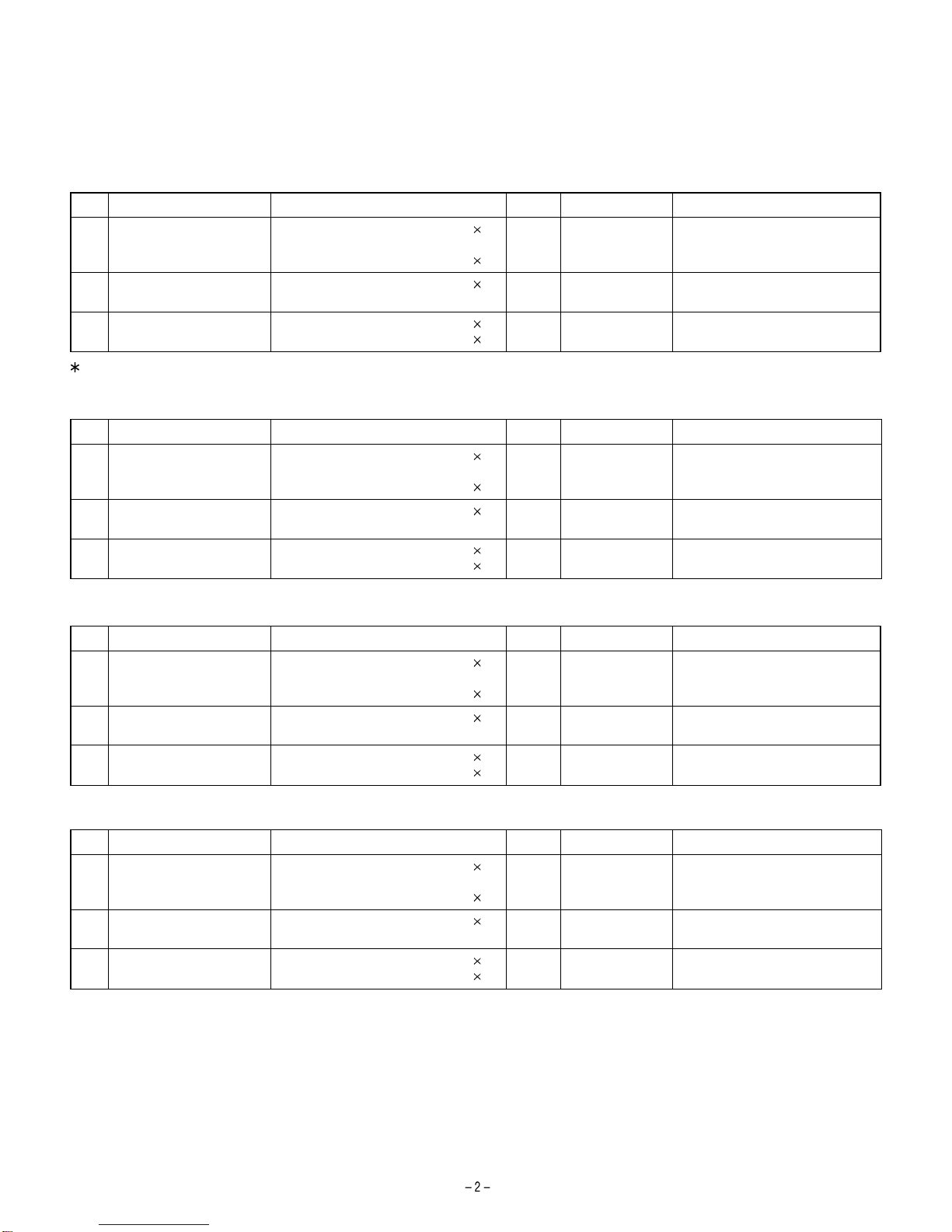
[ 3 ] CONSUMABLE PARTS
1. SUPPLY SYSTEM TABLE
A. Latin America
NO Name Content Life Model name Remark
1 Toner cartridge (Black)
<With IC> Toner
(Toner: Net Weight 475g)
Bag
10
10
180K AR-015LT Life setting by A4 (8.5"x11") 6%
coverage
2 Developer Developer
(Developer: Net Weight 400g) 10 500K AR-015CD
3 Drum kit Drum
Drum fixing plate 1
150k AR-015DR
For USA goverrnment
B. Middle East/Africa
NO Name Content Life Model name Remark
1 Toner cartridge (Black)
<With IC> Toner
(Toner: Net Weight 475g)
Bag
10
10
180K AR-015ET Life setting by A4 6% coverage
2 Developer Developer
(Developer: Net Weight 400g) 10 500K AR-015CD
3 Drum kit Drum
Drum fixing plate 1
150k AR-015DR
C. Europe
NO Name Content Life Model name Remark
1 Toner cartridge (Black)
<With IC> Toner
(Toner: Net Weight 475g)
Bag
10
10
180K AR-015LT Life setting by A4 (8.5"x11") 6%
coverage
2 Developer Developer
(Developer: Net Weight 400g) 10 500K AR-015CD
3 Drum kit Drum
Drum fixing plate 1
150k AR-015DR
D. Asia
NO Name Content Life Model name Remark
1 Toner cartridge (Black)
<With IC> Toner
(Toner: Net Weight 475g)
Bag
10
10
180K AR-015CT Life setting by A4 6% coverage
2 Developer Developer
(Developer: Net Weight 400g) 10 500K AR-015CD
3 Drum kit Drum
Drum fixing plate 1
150k AR-015DR
>>>>> USE FONT <<<<<
Helvetica/ Helvetica-Condensed/ Century-Schoolbook/ Symbol & OriginalFonts: (RingWorld2/RingFont2/Pa
Symbol/PartsCod)
- - - - - - - - - - - - - - - - - - - - - - - - - - - - - - - - - - - - - - - - - - - - - - - - - - - - - - -
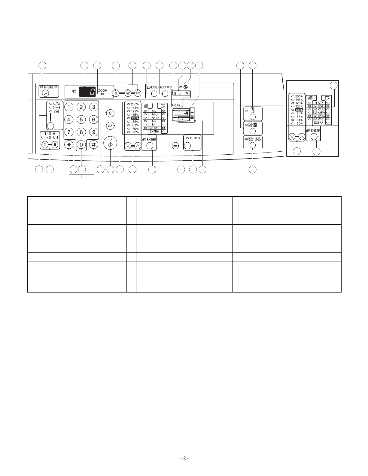
[ 4 ] EXTERNAL VIEWS AND INTERNAL STRUCTURES
3. OPERATION SECTION
1 INTERRUPT key and indicator 2 Copy quantity display 3 ZOOM indicator
4 Copy ratio display key 5 Zoom keys 6 PAPER SIZE ENTER key
7 AUDIT CLEAR key 8 PAPER SIZE indicators 9 Alarm indicators
10 POWER SAVE indicator 11 Output tray full indicator 12 B/W REVERSE key and indicator
13 XY-ZOOM key and indicator 14 AUTO/MANUAL/PHOTO key and indicators 15 Light and dark keys and indicators
16 Numeric keys 17 Zero key 18 CLEAR key
19 START key and indicator 20 CLEAR ALL key 21 PRESET RATIO selector keys and indicators
22 ORIGINAL SIZE ENTER key and
indicators 23 TRAY SELECT key 24 AUTO IMAGE key and indicator
25 Paper feed location/misfeed location
indicators 26 DUAL PAGE COPY key and indicator
Inch system
1312
1110987654321
8
14 15 1716
Not used
18 19 242322
2120 25
22
21
26

[ 7 ] SIMULATIONS
The table below shows the changed points in simulations. (Items marked with* are changed.)
Main
code Sub
code Contents Details of operation Initial value Set range
21 1 Maintenance cycle
setting Used to display the currently set maintenance cycle at the numbers
shown at right. When the set value is entered and the start key is
pressed, the set value is stored.
2* 0~7*
Key operation/Display
0: 2500 sheets 4: 150000 sheets
1: 5000 sheets 5: FREE (999999 sheets)
2: 25000 sheets* 6: 10000 sheets
3: 50000 sheets* 7: 7500 sheets
21 2 Mini maintenance
cycle setting Used to display the currently set mini maintenance cycle at the numbers
shown at right. When the set value is entered and the start key is
pressed, the set value is stored.
4 0~4*
Key operation/Display
0: 2500 sheets 4: 50000 sheets
1: 5000 sheets
2: 10000 sheets
3: FREE (999999 sheets)
26 6 Destination setting Used to display the current destination setting with the numbers at right.
After entering the set value, press the start key, and the set value is
stored.
70~13
Key operation/Display
0: Japan 8: EX AB series
1: USA (Inch series) 9: EX inch series (FC conformity)
2: Canada (Inch series) 10: EX AB series (FC conformity)
3: Germany 1 (AB series) (Australia, Newzealand)
4: UK (AB series) 11: China (AB series)
5: Not used 12: Taiwan (AB series)
6: France (AB series) 13: Germany 2 (AB series)
7: EX inch series
26 10 Model name input* Used to display and register the model name. 1 0~1
Key operation/Display
0: ARS140 1: AR5015
30 1 Machine sensor
operation check Used to check the sensor in the machine transport system with LED on
the operation panel.
Display
<Lighting at sensor ON>
Paper entry sensor : Machine position JAM LED
Duplex sensor : Manual feed tray position LED
Paper exit sensor : JAM LED

[10] MAINTENANCE
1. MAINTENANCE TABLE
: Check (Clean, adjust, or replace when required.) : Clean ▲: Replace : Adjust ✩: Lubricate
Unit name Part name When calling 25K 50K 75K 100K 125K 150K
Drum peripheral OPC drum – – – –
Cleaning blade – – – –
Side seal
MC unit
(MC charging electrode) – ( )()()()()()
(MC grid) – ( )()()()()()
(MC case) – ( )()()()()()
Transfer wire
Transfer paper guide
Developing section Developer – – – –
DV seal –
DV side seal –– –
SideMylar – –––––
Optical section Lamp unit Reflector
Mirror
No. 2/3 mirror unit Mirror
Pulley
CCD peripheral Lens
Glass Table glass
White Plate
Other Drive wire
Rail ✩ ✩ ✩ ✩
Document cover
Document size sensor
LSU Dust-proof glass
Paper feed section Multi paper feed
section Takeup roller
Paper feed roller
Spring clutch ✩ ✩ ✩ ✩
Paper transport section PS roller
Transport (paper exit) rollers
Spring clutch ✩ ✩ ✩ ✩
Fusing section Upper heat roller
Pressure roller
Pressure roller bearing ✩
Upper separation pawl
Lower separation pawl
Drive section Gears ✩ ✩ ✩ ✩
Belts
Paper exit section Ozone filter *1
*1 : Recommendable replacement time: 50K (Letter, 5% print)
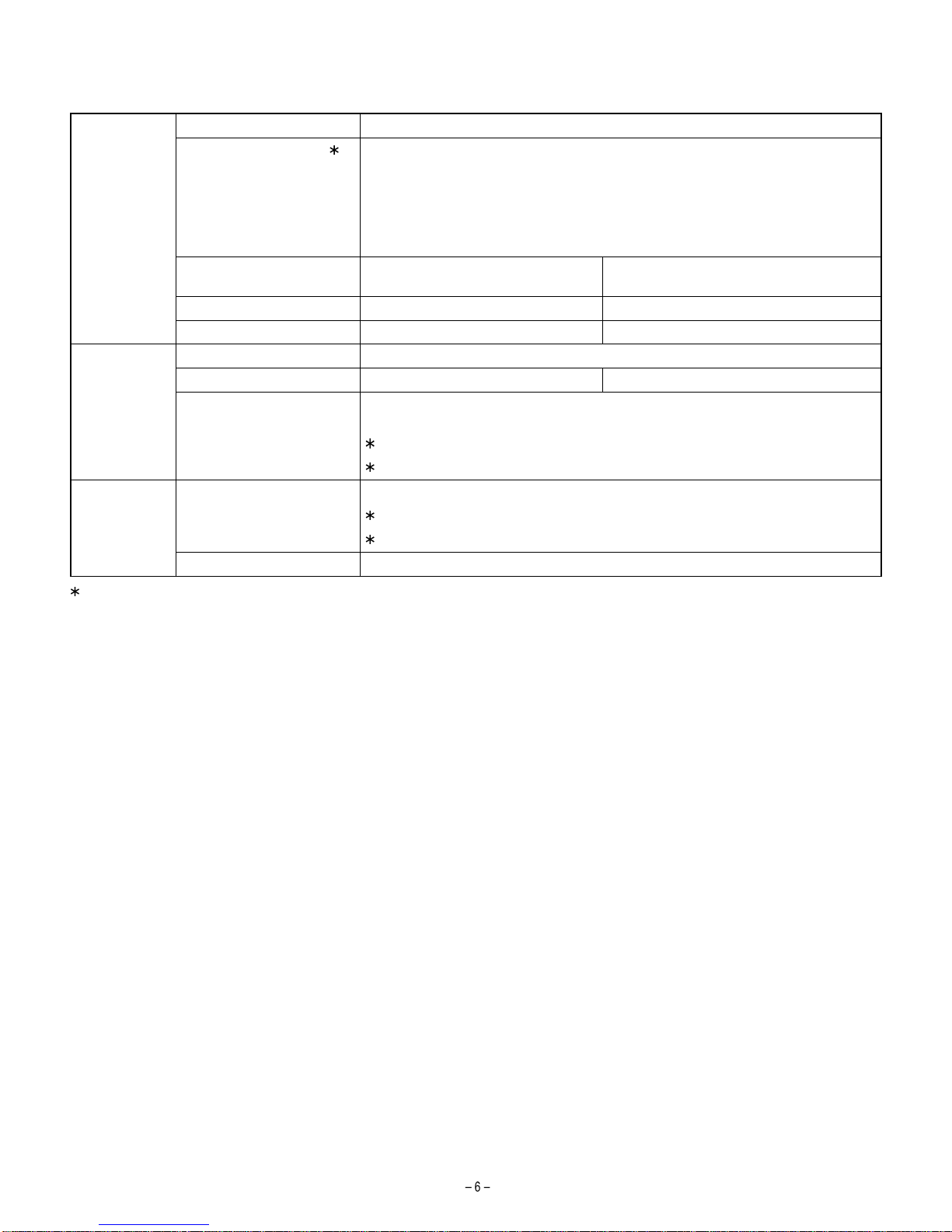
2. MAINTENANCE DISPLAY SYSTEM
According to the change in toner and developer life, the LED ON timing is changed.
Toner Life 18K
Remaining quantity check 1 a. Press and hold the density adjustment LIGHT key for more than 5 sec, and the machine
will enter the user program mode.
b. Press and hold the "%"key for more than 5 sec, and the remaining quantity will be
displayed on the copy quantity display in one of the following levels: (Remaining quantity
display levels: 100%, 75%, 50%, 25%, 10%, LO)
c. Press the density adjustment LIGHT key to cancel.
Remaining quantity NEAR EMPTY
About 10% EMPTY
LED ON Flash
Machine Operation allowed Stop
Developer Life 50K
LED ON at 50K of the developer count.
Machine Selection is available between Not Stop and Stop by Service Simulation (SIM 26-37) Setup.
(If Stop is selected, the LED will flash and stop at 50K)
Default: Not Stop
Clear: SIM 42-1
Maintenance LED Selection is available among 50K, 25K, 10K, 7.5K, 5K, and free (no lighting) with SIM 21-1.
Default: 25K
Clear: SIM 20-1
Machine Not stop.
1 : Installation of a new toner cartridge allows to display the remaining quantity.

[11] DISASSEMBLY AND ASSEMBLY
11. DEVELOPING SECTION
A. Developing box
a) Side mylar attachment reference
The side mylar attachment reference is shonw in the figure below.
12. PROCESS SECTION
B. Charger cleaning
1. Remove the MC holder unit
2. Remove the Screen grid
3. Push the electrode cleaner onto the electrode tip so that the elec-
trode tip comes into the electrode cleaner to clean. (repeat two or
three times.)
Note: Do not move the electrode cleaner with the electrode tip in it.
When cleaning, clean all the electrodes evenly.
D. Moquette F/R of process frame unit
To improve reliability of the drum unit, the AR-5015 must use the
following parts.
•Process frame unit : CFRM-0021QS67
•Moquette F : PSEL-0129QSZZ
•Moquette R : PSEL-0130QSZZ
0
0.5
B
0
0.5 A
0
0.5
D
00.5
C
Side mylar
DV side sheet
DV side sheet
Side mylar
(2)
(1)
(1)
Electrode cleaner
Electrode section
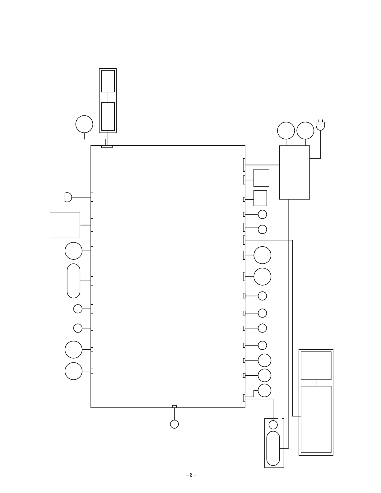
[13] ELECTRICAL SECTION
1. BLOCK DIAGRAM
MCU-PWB
CCD-PWB
APC-PWB
HVU
Power Supply PS-FAN
PS-SW
Polygon-Motor
Mirror-Motor
Fuser-Lamp
Copy-Lamp
Down-Load-CON
Toner-Motor MAIN-Motor
OPERATION PANEL
ERDH-OP-PWBCOPY-OP-PWB
HAND
PICK UP
SOL
CN15 CN19
PS
ROLLER
SOL
CN18 CN36 CN13 CN12
BD-PWB
LSU-PWB
CN4
CN6 CN5
FUSER COOLING FAN
CN23 CN24 CN20 CN35 CN2 CN1
SIDE
COVER
CASETTE
SWITCH SWITCH
CN14 CN22
DEV
SENSOR
CN27
CASETTE
PICK UP
SOL
HAND
PAPER
EMPTY
SENSOR
CASETTE
PAPER
EMPTY
SENSOR
CN32 CN33
PAPER
IN
SENSOR
CN28
SCANNER
HP
SENSOR
SCANNER
COVER
SWITCH
CN29 CN17
CN26
PAPER OUT
SENSOR
CN38
CRUM
UNIT
THERMISTER
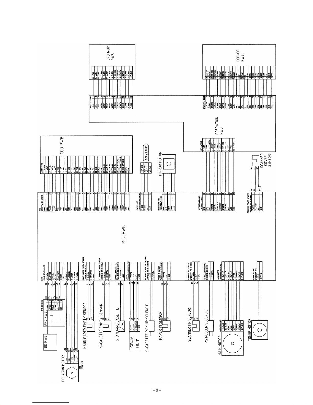
2. ACTUAL WIRING DIAGRAM
ACTUAL WIRING DIAGRAM 1/2
Other manuals for AR-5015 N
1
Table of contents
Other Sharp Copier manuals

Sharp
Sharp SF-815 User manual

Sharp
Sharp AR-150 SERIES User manual

Sharp
Sharp AR-LC1 User manual

Sharp
Sharp AR-RP3 User manual

Sharp
Sharp AR-151 User manual

Sharp
Sharp DX-C200 User manual

Sharp
Sharp AL-1640 - B/W Laser - Copier User manual

Sharp
Sharp AR-151 User manual

Sharp
Sharp Z-810 Assembly instructions

Sharp
Sharp MX-M283 User manual

Sharp
Sharp AR-C150 User manual

Sharp
Sharp SF-2218 User manual

Sharp
Sharp AR-651 How to use

Sharp
Sharp AL-1611 User manual

Sharp
Sharp AR-651 User manual

Sharp
Sharp AR-156 User manual

Sharp
Sharp AR-5600 series Online Setup guide

Sharp
Sharp AR-287 User manual

Sharp
Sharp AR-122E N User manual

Sharp
Sharp AR-407 User manual


