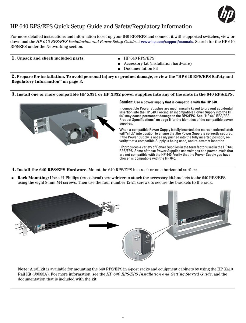
HP D7171A - NetServer - LPr User manual

HP NetServer LH 3/LH 3r
Power Supply Upgrade Kit
Installation Guide
HP Part Number 5967-2108
Printed in June 1998

ii
Notice
The information contained in this document is subject to change without notice.
Hewlett-Packard makes no warranty of any kind with regard to this
material, including, but not limited to, the implied warranties of
merchantability and fitness for a particular purpose. Hewlett-Packard shall
not be liable for errors contained herein or for incidental or consequential
damages in connection with the furnishing, performance, or use of this material.
Hewlett-Packard assumes no responsibility for the use or reliability of its software
on equipment that is not furnished by Hewlett-Packard.
This document contains proprietary information that is protected by copyright.
All rights are reserved. No part of this document may be photocopied,
reproduced, or translated to another language without the prior written consent of
Hewlett-Packard Company.
PentiumTM is a U.S. trademark of Intel Corporation.
Hewlett-Packard Company
Network Server Division
Technical Marketing / MS 49EU-FQ
5301 Stevens Creek Blvd.
PO Box 58059
Santa Clara, CA 95052-8059 USA
© Copyright 1998, Hewlett-Packard Company
Audience Assumptions
This guide is for the person who installs, administers, and troubleshoots LAN
servers. Hewlett-Packard Company assumes you are qualified in the servicing of
computer equipment and trained in recognizing hazards in products with
hazardous energy levels.

iii
Contents
Preface............................................................................................................. 1
Purpose of this Guide.................................................................................... 1
Contents of this Guide................................................................................... 2
Related Documentation................................................................................. 2
1 Introduction ................................................................................................. 3
Verifying Contents......................................................................................... 3
Prepare for Installation .................................................................................. 3
Tools You Need......................................................................................... 3
Installation Overview ..................................................................................... 3
Removing the Covers.................................................................................... 4
HP NetServer LH 3.................................................................................... 5
HP NetServer LH 3r .................................................................................. 7
2 Cage and Power Supply Installation .......................................................... 9
Introduction............................................................................................... 9
Power Supply Cage Installation............................................................... 10
Power Supply Installation........................................................................ 12
3 Installing the Fan Module.......................................................................... 15
Installing Fan Module.............................................................................. 15
Replacing the Covers.................................................................................. 17
HP NetServer LH 3.................................................................................. 17
HP NetServer LH 3r ................................................................................ 17
4 Warranty and Support............................................................................... 19
Hardware Warranty ..................................................................................... 19
HP Repair and Telephone Support.............................................................. 19
Index............................................................................................................... 23

1
Preface
Purpose of this Guide
This guide describes the steps you need to perform to install the HP NetServer
LH 3/LH 3r Power Supply Upgrade Kit, HP Product Numbers D6093A and
D6095A, into an HP NetServer LH 3/LH 3r. The kit adds a third power supply
module (PSM) to the two PSMs that come standard with the server. The third
PSM allows the server to keep operating should one of the original PSMs fail.
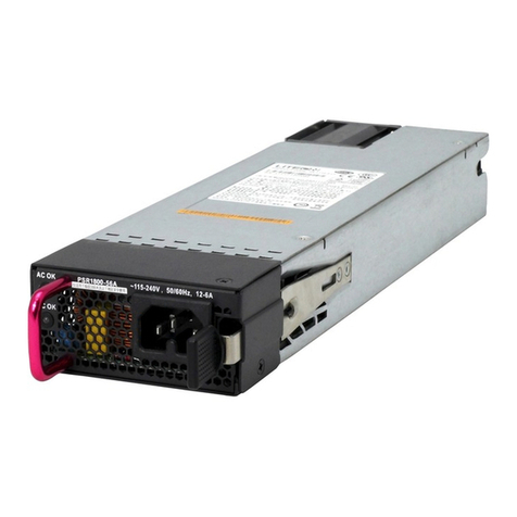
This accessory kit contains a PSM, a power supply fan module, a filler panel, and
a power supply cage for the HP NetServer LH 3 or LH 3r.
HP NetServer LH 3 HPNetServerLH 3r on Rack Slides
Figure P-1. NetServer Configurations
WARNING You must turn off power to the system and unplug power to
the unit before installing the accessory kit.

Preface
2
Contents of this Guide
This guide includes the following topics:
•An Introduction, including verifying the contents of the shipping box
•Installation instructions for installing the cage, power supply module, and
power supply fan module into the HP NetServer LH 3 or LH 3r
•Hardware warranty information
Related Documentation
The following documents describe the HP NetServer LH 3 and LH 3r:
•The HP NetServer LH 3/ LH 3 User Guide
•The HP NetServer LH 3 Installation Road Map
•The HP NetServer LH 3r Installation Road Map
•The Product and Service Reference Labels
•HP NetServer LH 3 and LH 3r Technical Reference Card
•HP NetServer LH 3and LH 3r documentation on the HP NetServer
Online Documentation CD-ROM

3
1 Introduction
Verifying Contents
The contents of the shipping box include:
• Power supply module (PSM)
• Power supply fan module
• Filler panel for the empty bay
• Power supply cage
Prepare for Installation
Gather the tools and the setup information you need to install the power supply
module, cage, and fan module before removing them from their packaging.
Tools You Need
To install this accessory kit, you need the following tools:
• A slotted head screwdriver, or TorxTM screwdriver.
• An anti-static service kit (3MTM 8501/8502/8503 or equivalent). This kit
includes a static-dissipating work surface, a chassis clip lead, and a wrist
strap.
Installation Overview
The Power Supply Upgrade Kit installation procedure is as follows:
1. Remove the HP NetServer front bezel and covers (Chapter 1).
2. Install the cage for the redundant power supply module (Chapter 2).
3. Install the redundant power supply module (Chapter 2).
4. Install the filler panel (Chapter 2).
5. Install an additional fan module in front of the existing power supply fan
module (Chapter 3).
6. Replace the HP NetServer covers (Chapter 1).

Chapter 1 Introduction
4
NOTE All components of the accessory kit must be installed in order
for the power supply module to function properly.
Removing the Covers
CAUTION Never operate this NetServer without first installing all
covers. Operating the system without all covers in place
reduces critical cooling airflow over some components, such
as hard disk drives and processor modules. Operating the
system without all covers in place may result in failure of
these components.
WARNING Before removing the covers, always disconnect the power
cord and unplug telephone cables. Disconnect the power cord
to avoid exposure to high energy levels that may cause burns
when parts are short-circuited by metal objects, such as tools
or jewelry. Disconnect telephone cables to avoid exposure to
shock hazard from telephone ringing devices.
Note that the power switch does not turn off the standby
power. Disconnect the power cord to turn off standby power.
If the backlight on the LCD display is on, standby power
is on.
CAUTION Wear a wrist strap and use a static-dissipating work surface
connected to the chassis at all times.

Chapter 1 Introduction
5
HP NetServer LH 3
To remove the covers:
WARNING Turn off the HP NetServer and disconnect the power cord and
telephone cord.
1. Unlock the bezel lock with the key from the key bag located on the rear of
the HP NetServer (see Figure 1-1).
2. To remove the front bezel, pull the top of the bezel away from the chassis,
and then lift the bezel up and off of the chassis.

Chapter 1 Introduction
6
3. Loosen the thumbscrew at the front of covers 1 and 3 and pull the covers
forward, using the handle on the covers, and then lift them off the chassis
(see Figure 1-1).
Thumbscrews
Tabs and Slots
3.
2.
Cover 1
Cover 3
4.
Figure 1-1. Removing the Covers (HP NetServer LH 3)

Chapter 1 Introduction
7
HP NetServer LH 3r
CAUTION Do not unscrew the LH 3r until you have extended the anti-
tip foot from under the front of the rack. This anti-tip device
must be extended to prevent the rack and LH 3r from tipping
over, which could damage the LH 3r and injure people.
To remove the covers:
1. Turn off the HP NetServer and disconnect all power and telephone cords.
2. Remove the screws securing the latch plate and the bezel hinge to the
rack. Do not unscrew the entire hinge or bracket from the chassis; remove
only the outer screws, so the hinge and the bracket remain attached to the
LH 3r chassis. Pull the LH 3r forward from the rack until the lockout
device engages with a click (see Figures 1-2 and 1-3).
Latch
Plate
Bezel
Hinge
Bezel
Figure 1-2. Sliding Out the NetServer From the Rack (NetServer LH 3r)

Chapter 1 Introduction
8
Cover 1
Cover 3
Do not
remove three
screws securing
the hinge to the LH 3r
Remove two screws
securing LH 3r to rack Remove two screws
securingLH3r torack
Do not
remove two
screwssecuring
the bracket to the LH 3r
Figure 1-3. Screw and Cover Locations (LH 3r)
3. Slide out the NetServer until the rail locks "click" into place.
4. Loosen the thumbscrew at the front of covers 1 and 3 and pull the covers
forward, using the handles on the covers, and then lift them off the chassis
(see Figure 1-4).
Cover 1
Cover 3
Figure 1-4. Removing the Covers (NetServer LH 3r)

9
2 Cage and Power Supply Installation
Introduction
This chapter shows how to mount an additional power supply cage in an HP
NetServer LH 3 or LH 3r. It then describes how to install the power supply
module (PSM) in the empty cage.
NOTE Before beginning this procedure:
•Shut down the HP NetServer operating system.
•Turn off the power switch on the front panel.
CAUTION Unplug the power cord from the power supply units.

Chapter 2 Cage and Power Supply Installation
10
Power Supply Cage Installation
Before installing the power supply cage, remove covers 1 and 3 as described in
Chapter 1.
To install the cage, follow these steps:
1. Loosen the two Torx screws on the front panel to be removed cabinet
(see Figure 2-1).
2. Remove the fan module behind the power supplies. To remove the fan
module, loosen the thumbscrew, then pull the fan assembly out of the
cabinet using the handle. See Figure 2-1.
FanModule
Figure 2-1. Fan Module Removal

Chapter 2 Cage and Power Supply Installation
11
3. Grasp the cage front panel and remove it from the cabinet
(see Figure 2-2). Set it aside.
Front Panel
Torx
Screws
Figure 2-2. Removing the Cage Front Panel
4. Remove the power supply module from the cage, then set the new cage
in the open bay.
5. Push in the cage most of the way. Align and guide the cage into the
chassis slowly.
6. There are three connectors to attach to install the power supply cage:
two large, white connectors that snap in place on the underside of the
circuit board, and one small, black connector that routes through the
rectangular slot in the circuit board and plugs into its top side.
First, attach the two large, white connectors. Attach the inner white
connector (farthest from you) first, then attach the outer white
connector. Make sure both connectors "click" into place and that the
plastic locks are secure.

Chapter 2 Cage and Power Supply Installation
12
Push the cage in all the way. Bring the small, black middle connector
up through the slot in the board above the power supply cage until the
connector "clicks" and the plastic lock is in place. Check to make sure
that the connector is secure. See Figure 2-3.
First, attach the two large, white
connectors.
Then, attach the small, black
connector.
Figure 2-3. Attaching the Power Supply Connectors
7. Fasten the cage in place with one screw on the side, lower rear. Fasten
the two screws into the rear chassis.
8. Reinstall the fan module.
Power Supply Installation
To install a power supply module (PSM) in the empty power supply cage, follow
these steps:
CAUTION When lifting a PSM, be prepared to support its weight. Hold
the PSM with two hands.

Chapter 2 Cage and Power Supply Installation
13
1. Set the new PSM in the open bay (see Figure 2-4). The power supply
can go into either side of the cage.
Set the new power supply
module in either side of the
open bay.
Figure 2-4. Setting the New Power Supply in the Open Bay
2. Push in the PSM, seat it firmly, and tighten the thumbscrews.
3. The new PSM fills only half the cage. Cover the other half with the
filler panel from the Upgrade Kit. Fasten the panel in place with its
thumbscrews.
The PSM is now installed. However, do not turn on the server until you install
the fan module from the Upgrade Kit. See Chapter 3.


15
3 Installing the Fan Module
Installing Fan Module
Once the power supply cage and module are installed in the server, install the fan
module from the Power Supply Upgrade Kit. Server power should still be off, and
the covers 1 and 3 should be off the NetServer. The module includes two fans. It
mounts directly in front of the existing power supply fan module.
1. Slide the fan module that you removed back into place.
2. Slide the new fan module into place in front of the existing power supply
fan module.
3. Fasten the fan module in place and secure it with its thumbscrew. See
Figure 3-1.
Slide the new
fan module into
place.
Figure 3-1. Installing the Fan Module

Chapter 3 Installing the Fan Module
16
4. Replace covers 1 and 3. See "Replacing the Covers," in this section, for
details.
5. Remove the yellow tamper evident plug (not pictured) from the power
supply. Then plug in the power supply cord. The power cord retainer
holds the plug in place. To attach the power cord retainer, push up on the
metal piece underneath and secure it with the locking mechanism. See
Figure 3-2.
Figure 3-2. Power Cord Retainer
6. Check that the green LED at the front of each power supply is on. The
LED confirms that the power supply is functioning.
Other manuals for D7171A - NetServer - LPr
117
This manual suits for next models
7
Table of contents
Other HP Power Supply manuals

HP
HP J2962A Installation and operating manual

HP
HP 6205C Service manual

HP
HP 6034A User manual

HP
HP 59501A User manual

HP
HP 6269B Installation instructions

HP
HP 640 RPS/EPS User manual

HP
HP A Series Service manual

HP
HP E3610A Service manual

HP
HP D7171A - NetServer - LPr Installation and operation manual

HP
HP StorageWorks MSA20 Guide