HP PSR1800-56A User manual

HP PSR1800-56A
Power Supply
User Guide
Part number: 5998-4302
Document version: APW100-20130829
5998-4302

Legal and notice information
© Copyright 2013 Hewlett-Packard Development Company, L.P.
No part of this documentation may be reproduced or transmitted in any
form or by any means without prior written consent of Hewlett-Packard
Development Company, L.P.
The information contained herein is subject to change without notice.
HEWLETT-PACKARD COMPANY MAKES NO WARRANTY OF ANY
KIND WITH REGARD TO THIS MATERIAL, INCLUDING, BUT NOT
LIMITED TO, THE IMPLIED WARRANTIES OF MERCHANTABILITY AND
FITNESS FOR A PARTICULAR PURPOSE. Hewlett-Packard shall not be
liable for errors contained herein or for incidental or consequential
damages in connection with the furnishing, performance, or use of this
material.
The only warranties for HP products and services are set forth in the
express warranty statements accompanying such products and services.
Nothing herein should be construed as constituting an additional
warranty. HP shall not be liable for technical or editorial errors or
omissions contained herein.

i
Contents
Power supply overview············································································1
Technical specifications ·····································································1
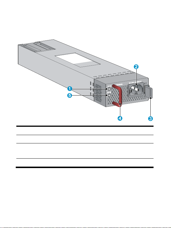
Appearance························································································3
LEDs ·····································································································3
Installing and removing a power supply ···············································5
Safety precautions··············································································5
Tools ····································································································5
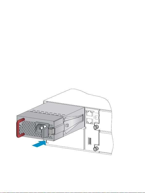
Installing and removing a power supply··········································6
Installing the power supply ··························································6
Connecting the AC power cord ··················································9
Removing the power supply······················································ 11
Support and other resources································································ 14
Contacting HP·················································································· 14
Subscription service··································································· 14
Related information ········································································· 15
Documents ·················································································· 15
Websites····················································································· 15
Conventions ····················································································· 15

1
Power supply overview
The PSR1800-56A (JG840A) is a power supply with AC input and DC
output. It provides up to 1800 W output and delivers the following
features:
Feature Description
Protection
Protection against over-current input,
under-voltage input, over-voltage output,
over-current output, output short circuit, and
over-temperature.
Redundancy The PSR1800-56A power supplies can operate
in redundant mode, and support load sharing.
Hot swapping You can replace a power supply when the switch
is operating.
Technical specifications
Item Specifications
Rated input voltage 100 VAC to 240 VAC @ 50 Hz or 60
Hz
Maximum input voltage 90 VAC to 264 VAC @ 47 Hz to 63 Hz
Maximum input current 13 A
Output voltage –56 V

2
Item Specifications
Output current
•32.2 A (201 VAC to 240 VAC input
voltage)
•19.6 A (100 VAC to 200 VAC input
voltage)
Maximum output power
•1800 W (201 VAC to 240 VAC input
voltage)
•1100 W (100 VAC to 200 VAC input
voltage)
Dimensions (H × W ×
D)
40.1 × 82.6 × 297.7 mm (1.58 × 3.25
× 11.72 in)
Operating temperature –10°C to +55°C (14°F to 131°F)
Relative humidity 5% to 95%
NOTE:
W
hen the input voltage is in the range of 100 VAC to 200 VAC, the
output power of the power supply decreases to 1100 W. You need
to determine whether the output power meets the requirements for
the device operation. If not, take necessary measures. For more
information, see device installation manuals.

3
Appearance
Figure 1 PSR1800-56A
(1) Input status LED (AC OK) (2) AC input socket
(3) Latch
(4) Handle (The handle is in red, indicating that the air ventilation is
performed by exhausting air from the inside to the outside.)
(5) Output status LED (DC OK)
LEDs
A PSR1800-56A has two status LEDs on its front panel. The following
table lists the LED status and description.

4
LED Status Description
Input status
LED (AC OK)
Steady green The power input is normal.
Off No power input or the power
input is abnormal.
Output
status LED
(DC OK)
Steady green The power output is normal.
Steady red The power output is abnormal.
Off No power output.

5
Installing and removing a power supply
Safety precautions
To avoid possible bodily injury and power supply and device damage,
follow these safety precautions:
•When you install and remove a power supply, always wear an
ESD wrist strap and make sure it makes good skin contact and is
well grounded.
•Before you install the power supply, make sure the voltage of the
power source is the same as the rated voltage of the power supply,
and the output voltage of the power supply is the same as the
required voltage.
•Do not touch any naked cable or terminal of the power supply.
•Do not place the power supply in a wet area, and prevent liquid
from flowing into the power supply.
•To avoid power supply damage, do not open the power supply.
When the internal circuits or components of the power supply fail,
contact the maintainer for examining and repairing.
Tools
Prepare an ESD wrist strap and a flat-blade screwdriver yourself.

6
Installing and removing a power supply
IMPORTANT:
Before installation, make sure the power supply model is as
required. For more information about the device requirements, see
the installation guide of the device.
Installing the power supply
To avoid bodily injury or device damage, follow the steps in Figure 2 to
install the power supply.
Figure 2 Installation procedure
Install the power supply
Connect the power cord
Turn on the circuit breaker

7
To install the power supply:
1. Put on the ESD wrist strap, making sure the strap makes good skin
contact and is well grounded.
2. Unpack the power supply and verify that the power supply model
is as required.
3. As shown in Figure 3, with the upside of the power supply up, hold
the handle of the power supply with one hand and the bottom of
the power supply with the other, and then slide the power supply
slowly along the guide rails into the slot. When the power supply
is completely inserted into the slot, you can hear that the latch of
the power supply clicks into the slot.
Figure 3 Installing the power supply

8
Figure 4 Appearance of the power supply after installation
IMPORTANT:
•To avoid damaging or bending the terminals of the power supply,
if the insertion direction is incorrect during the installation, you
must pull the power supply out, adjust the direction, and insert it
again.
•To remove the filler panel (if any) from the power supply slot on
the device, insert a flat-blade screwdriver through the handle and
pull the filler panel outward along the guide rails, as shown
in Figure 5.
•Keep the filler panel and the packaging box and packaging bag
of the power supply for future use.

9
Figure 5 Removing the filler panel
Connecting the AC power cord
CAUTION:
•The PSR1800-56A power supply must use the high-temperature
resistant C15 connector power cord delivered with the power
supply.
•Turn off the circuit breaker before connecting the power cord.

10
To connect the power cord:
1. As shown in Figure 6, plug the female connector end of the AC
power cord into the AC input socket on the switch.
Figure 6 Connecting the AC power cord
2. As shown in Figure 7, use a cable tie to secure the power cord to
the handle of the power supply.
Figure 7 Securing the AC power cord

11
3. Plug the other end of the AC power cord into the socket strip of the
power source, and turn on the circuit breaker of the power source.
4. Examine the LED on the power supply. If the input status LED (AC
OK) is steady green, the power cord is successfully connected. If
the LED is off, examine the installation conditions, troubleshoot the
problems, and try again until the LED is normal.
Removing the power supply
To avoid bodily injury or device damage, follow the steps in Figure 8 to
remove the power supply.
Figure 8 Removing procedure
Turn off the circuit breaker
Remove the power cord
Remove the power supply

12
To remove the power supply:
1. Turn off the circuit breaker of the power cord.
2. Put on the ESD wrist strap, making sure the strap makes good skin
contact and is well grounded.
3. Loosen the cable tie, and remove the power cord.
4. As shown in Figure 9, press the latch towards the handle, and pull
the power supply along the guide rails until it is part-way out.
5. Grasp the handle of the power supply with one hand, and hold
the bottom of the power supply with the other hand to pull the
power supply slowly along the guide rails out of the slot.
Figure 9 Removing the power supply
1
2

13
6. Put the removed power supply on an antistatic mat or into its
package.
NOTE:
If you do not insert another power supply into the slot after removing
the power supply, install the filler panel to the power supply slot to
prevent dust from entering the chassis.

14
Support and other resources
Contacting HP
For worldwide technical support information, see the HP support
website:
http://www.hp.com/support
Before contacting HP, collect the following information:
•Product model names and numbers
•Technical support registration number (if applicable)
•Product serial numbers
•Error messages
•Operating system type and revision level
•Detailed questions
Subscription service
HP recommends that you register your product at the Subscriber's
Choice for Business website:
http://www.hp.com/go/wwalerts
After registering, you will receive email notification of product
enhancements, new driver versions, firmware updates, and other
product resources.

15
Related information
Documents
To find related documents, browse to the Manuals page of the HP
Business Support Center website:
http://www.hp.com/support/manuals
•For related documentation, navigate to the Networking section,
and select a networking category.
•For a complete list of acronyms and their definitions, see HP
FlexNetwork Technology Acronyms.
Websites
•HP.com http://www.hp.com
•HP Networking http://www.hp.com/go/networking
•HP manuals http://www.hp.com/support/manuals
•HP download drivers and
software http://www.hp.com/support/downloads
•HP software depot http://www.software.hp.com
•HP Education http://www.hp.com/learn
Conventions
This section describes the conventions used in this documentation set.

16
Command conventions
Convention Description
Boldface Bold text represents commands and keywords
that you enter literally as shown.
Italic Italic text represents arguments that you
replace with actual values.
[ ] Square brackets enclose syntax choices
(keywords or arguments) that are optional.
{ x | y | ... }
Braces enclose a set of required syntax
choices separated by vertical bars, from
which you select one.
[ x | y | ... ]
Square brackets enclose a set of optional
syntax choices separated by vertical bars,
from which you select one or none.
{ x | y | ... } *
Asterisk-marked braces enclose a set of
required syntax choices separated by vertical
bars, from which you select at least one.
[ x | y | ... ] *
Asterisk-marked square brackets enclose
optional syntax choices separated by vertical
bars, from which you select one choice,
multiple choices, or none.
&<1-n>
The argument or keyword and argument
combination before the ampersand (&) sign
can be entered 1 to n times.
# A line that starts with a pound (#) sign is
comments.

17
GUI conventions
Convention Description
Boldface
Window names, button names, field names,
and menu items are in bold text. For example,
the New User window appears; click OK.
> Multi-level menus are separated by angle
brackets. For example, File >Create >Folder.
Symbols
Convention Description
WARNING
An alert that calls attention to important
information that if not understood or followed
can result in personal injury.
CAUTION
An alert that calls attention to important
information that if not understood or followed
can result in data loss, data corruption, or
damage to hardware or software.
IMPORTANT An alert that calls attention to essential
information.
NOTE An alert that contains additional or
supplementary information.
TIP An alert that provides helpful information.
Table of contents
Other HP Power Supply manuals
Popular Power Supply manuals by other brands

StarTech.com
StarTech.com ATXPOW380HS Instruction guide

Altronix
Altronix ALTV1224C4 manual

Matsusada Precision
Matsusada Precision CO Series instruction manual

Delta Electronics
Delta Electronics Delphi V48SR datasheet

Linergy
Linergy SPY CENTER BASIC SCB050 Series manual

Puls
Puls FPS300.245-049-112 installation manual