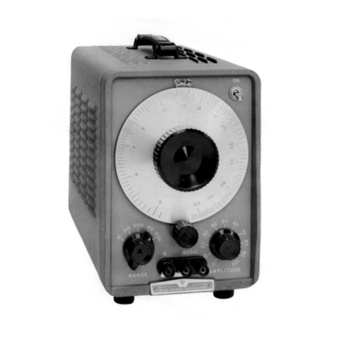
HP 209A Service manual

HP Archive
This vintage Hewlett Packard document was preserved
and distributed by
www. hparchive.com
Please visit us on the web !
On-line curator: Thomas Chrapkiewicz

~
Ol
o
N
ll.
:I:
·,
OPERATING
AND
SERVICE
MANUAL
SINE
IS·QUARE
OSCILLATOR
209A
HEWLETT.
PACKARD
www.HPARCHIVE.com
:I:
~
N
o
IQ
»

HEWLETT"
PACKARD
CE
RTI
FI CATION
The Hewlett-Packard Company certifies that this instrument was
thoroughly tested and inspected and found to meet its published
specifications when
it
was shipped from the factory. The Hewlett-
Packard Company further certifies that its calibration measure-
ments are traceable to the
U.S.
National Bureau
of
Standards to
the extent allowed by the Bureau's calibration facility.
WARRANTY
AND
ASSISTANCE
All
Hewlett-Packard products are warranted against defects
in
materials and workmanship. This warranty applies for one year
from the date of delivery, or,
in
the case of certain major
compo-
nents listed
in
the operating manual, for the specified period.
We
will
repair or replace products which prove to
be
defective during
the
warranty
period provided
they
are
returned
to
Hewlett-
Packard.
No
other warranty
is
expressed or implied.
We
are not
liable for consequential damages.
Service contracts or customer assistance agreements are available
for Hewlett-Packard products
that
require maintenance and re-
pair on-site.
Forany assistance, contact your nearest Hewlett-Packard Sales and
Service Office. Addresses are provided
at
the back of this manual.
www.HPARCHIVE.com

OPERATING
AND
SERVICE
MANUAL
-hp- Part No. 00209-90002
MODEL
SINE/SQUARE
209A
OSCILLATOR
Serials Prefixed: 818-
Copyright Hewlett-Packard Company 1968
P.O. Box 301, Loveland, Colorado, 80537 U.S.A.
www.HPARCHIVE.com
Printed:
MAY
1970

Table
of
Contents
Model209A
TABLE
OF
CONTENTS
APPENDICES
A. CODE LIST
OF
MANUFACTURERS
B.
SALES AND SERVICE OFFICES
C.
MANUAL BACKDATING CHANGES
Section Page
VI REPLACEABLE PARTS
6-1
6-1. Introduction
6-1
6-4. Ordering Information
6-1
6-6. Non-Listed Parts
6-1
Section Page
VII CIRCUIT DIAGRAMS
7-1
7-1.
Introduction
7-1
7-3. Schematic Diagrams
7-1
7-5.
Component
Location Diagrams
7-1
Page
5-23.
5-26.
5-28.
5-29.
5-30.
Section
VMAINTENANCE
(Cont'd)
5-8. Distortion Check 5-3
5-9.
Output
Voltage and Impedance
Check (Sine Wave) 5-4
5-10.
Output
Control Check
(Sine Wave) 5-4
5-11. Balance Check (Sine Wave) 5-4
5-12.
Output
Voltage Check
(Square Wave) 5-4
5-13. Rise Time Check
(Square Wave) 5-5
5-14.
Symmetry
Check
(Square Wave) 5-5
5-15. Sync
Output
Check 5-5
5-16.
Sync
Input
Check 5-5
5
-1
7. Cover Removal . . . . . . . . . . . . . . . . . 5-6
5-22. Adjustment and Calibration
Procedure 5-6
Introduction
5-6
Power Supply 5-6
Bias Adjustment 5-6
AGC Adjustment 5-6
AGC
and
Frequency
Adjustment 5-6
5-31. High Frequency Adjustment 5-7
5-32. Distortion Adjustment 5-7
5-33.
Symmetry
Adjustment 5-7
5-34.
Factory
Selected Components 5-7
5-36. Troubleshooting Procedures 5-8
5-37.
Front
Panel Procedure 5-8
5-40. Detailed Circuit
Troubleshooting 5-8
Section Page
VMAINTENANCE 5-1
5-1. Introduction
5-1
5-4. Performance Checks 5-1
5-6. Dial Accuracy Check
5-1
5-7. Flatness Check
5-1
Section Page
IGENERAL INFORMATION
1-1
1-1.
Introduction
1-1
1-3. Specifications
1-1
1-5. Description
1-1
1-10. Instrument/Manual Identification
..
1-1
Section Page
II INSTALLATION
2-1
2-1.
Introduction
2-1
2-3. Initial Inspection
2-1
2-5. Power Requirements
2-1
2-7. Grounding Requirements
2-1
2-10. Installation
2-1
2-12. Bench Mounting
2-1
2-14. Rack Mounting
2-1
2-16. Combination Mounting
2-1
2-18. Repackaging for Shipment
2-1
Section Page
III OPERATING INSTRUCTIONS
3-1
3-1. Introduction
3-1
3-3. Turn On Procedure
3-1
3-5. Operating Considerations
3-1
3-6. Floating
Output
3-1
3-8. Balance
3-1
3-10. Synchronization
3-1
3-13.. Low Distortion
3-1
Section Page
IV THEORY
OF
OPERATION
4-1
4-1. Introduction
4-1
4-4. Block Diagram Description ,
4-1
4-5. Bridge and Amplifier
4-1
4-9. Peak Comparator and AGC _
4-1
4-13. Buffer Amplifier 4-2
4-15. Sine-Square Converter 4-2
4-17. Detailed Circuit Description 4-2
4-25. Power Supply 4-2
iii
www.HPARCHIVE.com

Model209A
LIST
OF
TABLES
Table
of
Contents
Number
Page
1-1. Specifications
1-0
5-1. Required Test Equipment 5-0
5-2. Dial Accuracy Check
5-1
5-3. Flatness Check 5-2
Number
Page
5-4. Distortion Check
5-3
5-5. Factory Selected Components
5-7
5-6. Front Panel Symptoms
5-8
6-1. Replaceable Parts
6-2
LIST
OF
ILLUSTRATIONS
Number
Page
1-1.
Model
209A Sine/Square Oscillator
1-1
2-1. Dimensions
2-2
3-1. Description
of
Controls and Connectors 3-0
4-1. Model209A Block Diagram 4-0
4-2.
RC
Frequency Network Characteristics
4-1
5-1. Dial Accuracy Check
5-1
5-2. Flatness Check 5-2
5-3. 2
MHz
Distortion Check
5-3
5-4. Balance Check 5-4
5-5. Sync Input Check
5-5
6-1. Front Panel Exploded View 6-4
7-1. Oscillator Schematic
(AI)
7-3/7-4
7-2. Power Supply Schematic (A2) 7-5/7-6
iv
www.HPARCHIVE.com

Section I
-RANGES-
Table 1-1. Specifications
SQUARE
WAVE
Model209A
Frequency: 4
Hz
to 2
MHz
in 6ranges.
-PERFORMANCE
RATINGS-
Dial
Accuracy: +/-3%
of
frequency setting.
Flatness:
At
maximum output into 600 ohm load.
1kHz reference.
Low
Distortion
+/-1%
+/-0.5%
+/-1% +/-5%
Mode
Output
Voltage:
20 V
pop
open circuit
symmetrical about 0
V.
Output can be floated
up to +/-500 Vpeak between output and
chassis ground.
Rise and Fall Time:
less
than 50
ns.
Symmetry:
+/-5%
Output Impedance: 600 to 900 ohms depending
upon setting
of
output control.
Normal
Mode
+5%
-1%
+/-0.5%
+/-1% +/-5%
(Hz) 4
Distortion:
100 300k
1M
2M
-EXTERNAL
SYNCHRONIZATION-
Sync Impedance: 10 kilohm.
1.0
-40
\
--
NORMAL
MODE
/
*- - - - LOW
D1ST.
MODE
I
0.5
/
46
.,
C
i:
0.3
\
50
Q:
I
c
t:;
0.2
V
54
Ci
\
0.1
60
20
60
100
200
FREQUENCY-Hz
20DK
60CK
2M
Sync Output: Sine
wave
in phase with output;
amplitude working into 1megohm shunted by
100 pF
is
greater than 1.7 V
rms
from 4
Hz
to 50
kHz, greater than
.1
Vfrom 50 kHz to 2
MHz.
Sync Input: Oscillator can be synchronized to
external signal. For 5 V rms input, sync
frequency can be
as
much
as
+/-7%
away from
set frequency (sync range). Sync range
is
alinear
function
of
sync voltage.
--
Hum
and Noise:
less
than 0.01%
of
output.
-OUTPUT
CHARACTERISTICS-
SINE
WAVE
Output Voltage: 5 V
rms
(40
mW)
into 600 ohms;
10 Vopen circuit. Output can be floated up
to
+/-500 Vpeak between output and chassis
ground.
Output Impedance: 600 ohms.
Output Control: 20
dB
range continuously
adjustable.
Output Balance: greater than 40
dB
below 20 kHz.
1-0
-GENERAL-
Operating Temperature: Instrument will operate
within specifications from
0%
Cto
55%
C.
Storage Temperature:
40%
C
to
+75%
C
Power: AC-Line 115V
or
230V +/-10%,48
Hz
to
440 Hz.
less
than 7
W.
Dimensions:
Refer to Figure 2-1, page 2-2.
Accessories Available: HP
1l075A
Instrument Case.
www.HPARCHIVE.com

Model209A
SECTION
I
GENERAL
INFORMATION
Section I
1-1.
INTRODUCTION.
1-2.
This section contains general information about
the
-hp-
Model 209A Sine/ Square Oscillator.
Throughout this manual the instrument will
be
referred to
as
the Mode1209A.
1-3.
SPECIFICATIONS.
1-4.
Table
1-1
lists the specifications for the Model
209A.
1·5.
DESCRIPTION.
1-6.
The Model 209A
is
aversatile signal source with
independent sine
wave
and square
wave
outputs at
frequencies from 4
Hz
to 2
MHz.
The square
wave
amplitude
is
variable to amaximum
of
20 volts
peak-to-peak into open circuit. The sine
wave
amplitude
is
variable to amaximum
of
10 volts rms
into open circuit from aconstant 600 ohm source.
When
working into a600 ohm load, the maximum
output level
is
5volts rms.
1-7.
Balanced
output can be obtained by
disconnecting the grounding strap at the rear
of
the
instrument. This isolates the chassis from the cabinet
and line ground. The sine
wave
output
will
balance to
greater than 40 dB, at frequencies below 20 kHz,
with the chassis isolated.
1-8.
The Model 209A can
be
synchronized with an
external source. With a 5 volt rms sync input, the
external source may vary
as
much
as
+/-7%
in
frequency and the Model 209A will remain
synchronized.
1-9.
Async output
of
1.7 volts rms
is
also available
at the same front panel terminal used to accept an
external sync source.
1-10.
INSTRUMENT/MANUAL
IDENTIFICATION.
1-11. Hewlett-Packard
uses
atwo-section serial
number. The first section (prefix) identities aseries
of
instruments. The last section (suffix) identifies a
particular instrument within the series.
If
aletter
is
included with the serial number, it identifies the
country in which the instrument
was
manufactured.
If
the serial prefix
of
your instrument differs from
the one on the title
page
of
this manual, achange
sheet will be supplied to make this manual
compatable with newer instruments or the backdating
information in Appendix C
will
adapt this manual to
earlier
instruments.
All
correspondence with
Hewlett-Packard should include the complete serial
number.
Figure
1-1.
Model 209ASine/Square Oscillator
1-1
www.HPARCHIVE.com

Model209A
SECTION
II
INSTALLATION
Section II
2-1.
INTRODUCTION.
2-2.
This
section
contains information and
instructions necessary for installing and shipping the
Model 209ASine/Square Oscillator. Included are
initial inspection procedures, power and grounding
requirements,
installation
information, and
instructions for repackaging for shipment.
2-3.
INITIAL
INSPECTION.
2-4. This instrument was carefully inspected
both
mechanically and electrically before shipment.
It
should be physically free
of
mars or scratches and in
perfect electrical order upon receipt. To confum this,
the instrument should be inspected for physical
damage that occurred in transit.
If
the instrument
was
damaged in transit, me aclaim with the carrier. Test
the electrical performance
of
the instrument using
Performance Checks outlined in Section V.
If
there
is
damage or deficiency,
see
the warranty on the inside
front cover
of
this manual.
2-5.
POWER
REQUIREMENTS.
2-6. The standard Model 209A will operate from any
source
of
115 or 230 volts (+/-10%), at 48 to 440 Hz.
With the instrument disconnected from the ac power
source, move the voltage selector switch (located on
the rear panel) so the designation appearing on the
switch matches the voltage
of
the power source
to
be
used. Power dissipation
is
less than 7watts.
2-7.
GROUNDING
REQUIREMENTS.
2-8. To protect operating personnel, the National
Electrical
Manufacturers Associatfon (NEMA)
recommends that the instrument cabinet be
grounded. The standard Model 209A
is
equipped with
athree-conductor power cable which, when plugged
in
to
an
appropriate receptacle, grounds the
instrument. The offset pin on the power cable
three-prong connector
is
the ground connection.
2-9. To preserve the protection feature when
operating the instrument from atwo-contact outlet,
use athree-prong
to
two-prong adapter and connect
the green pigtail on the adapter
to
earth ground.
2·10.
INSTALLATION.
2-11. The Model 209A
is
fully transistorized;
therefore, no special cooling
is
required. However, the
instrument should not be operated where the ambient
temperature exceeds
55
0C(1310F).
2-12.
BENCH
MOUNTING.
2-13. The Model 209A
is
shipped with plastic feet
and tilt stand in place, ready for use
as
abench
instrument.
2-14.
RACK
MOUNTING.
2-15. The Model 209A may be rack mounted by
using an adapter frame (-hp- Part No. 5060-0797).
The adapter frame
is
arack frame that accepts any
combination
of
-hp- submodular units.
It
can be rack
mounted only. For additional information, address
inquiries
to
your -hp- Sales and Service office. (See
Appendix Bfor office locations.)
2-16.
COMBINATION
MOUNTING.
2-17. The Model 209Amay be mounted in
combination with other submodular units
by
using a
Combining
Case
(-hp- Model 1051A or 1052A). The
Combining
Case
is
afull-module unit which accepts
various combinations
of
submodular units. Being a
full-module unit, it can be bench or rack mounted
and
is
analogous to any full-module unit.
2-18.
REPACKAGING
FOR
SHIPMENT.
2-19. The following paragraphs contain ageneral
guide for repackaging
of
the instrument for shipment.
Refer to Paragraph 2-20
if
the original container
is
to
be used;
2-21
if
it
is
not.
If
you have any questions,
contact your local -hp- Sales and Service Office. (See
Appendix Bfor office locations.)
2-1
www.HPARCHIVE.com
Section II Model209A
-----NOTE-----
If
the instrument
is
to
be
shipped
to Hewlett-Packard for
service
or
repair,
attach atag
to
the
instrument identifying the owner
and indicating the service or repair
to be accomplished; include the
model number and full serial
number
of
the instrument. In any
correspondence,
identify the
instrument by model number and
full
serial number.
2-20.
If
the original container
is
to be used, proceed
as
follows:
a.
Place the instrument in the original
container
if
available.
If
the original
container
is
not available, one can be
purchased from your nearest
-hp-
Sales
and
Service Office.
b. Ensure that the container
is
well
sealed with
strong tape or metal bands.
2-21.
If
the original container
is
not to be used,
proceed
as
follows:
a.
Wrap
the instrument in heavy paper or
plastic before placing it in an inner
container.
b. Place packing material around
all
sides
of
the
instrument and protect the panel face with
cardboard strips.
c.
Place the instrument and inner container in a
heavy carton or wooden box and
seal
with
strong tape or metal bands.
d.
Mark
the
shipping
container
with
"DELICATE INSTRUMENT", "FRAGILE"
etc.
Dimensions:
209A
TOP
8
(203,21
"-----------,,L
~
5i
('30'21~
~
t
(10.3)
DIMENSIONS IN INCHES AND
(MILLIMETERS)
[T
SIDE
6f2
~
(154,e)
~
e"
~
Figure 2-1. Dimensions
2-2
www.HPARCHIVE.com

Section III Model209A
2
SYNC
""""
I
"'AX
6000
3
9
10
,",-LINE
SELECTOR
o
~
IIS/230V±
10%
48-440""
TVA
MAX
CHANGE
FREQ.
SLOWLY
I
,OW
NORM OISl.
""
~~~
~
~ ~
CD
RANGE Switch: Selects frequency range or
OFF position.
eD
Frequency Dial: Selects frequency within
desired range. Dial setting multiplied by
RANGE switch position indicates output
frequency.
oFrequency Vernier: Provides fine tuning
of
frequency dial.
oSquare
Wave
Amplitude Control: Varies
Square
Wave
output level to 20 volts
peak-to-peak, open circuit.
eD
Sine
Wave
Amplitude Control: Varies Sine
Wave
output level over a20
dB
range to 10
volts rms, open circuit (5 volts rms into 600
ohms).
CD
Sine
Wave
Output Terminal: 600 ohm sine
wave
output at afrequency and amplitude
determined
by
control settings.
CD
Square
Wave
Output Terminal: 600 ohm
square
wave
output at afrequency and
amplitude determined by control settings.
CD
SYNC
Terminal: (1) Input terminal for an
external sync signal. (2) Output terminal for
1.7 volt rms sine
wave
sync signal.
CD
Ground Strap: Connects the floating circuit
ground to power ground.
®Voltage Selector Switch: Selects line voltage
of
115 volts or 230 volts
AC.
®
AC
Power Receptacle: Mates with power
cord supplied with this instrument for line
voltage connection.
@NORM/LOW DIST. Switch: Selects normal
or low distortion below 100 Hz.
Figure 3-1. Description
of
Controls and Connectors
3-0 www.HPARCHIVE.com

Mode1209A
3·1.
INTRODUCTION.
SECTION
III
OPERATING
INSTRUCTIONS
3-8.
BALANCE.
Section III
3-2. This section contains information
as
an aid
to
operating the Model 209A. Included are control and
connector descriptions (Figure 3-1), and some special
operating considerations.
3-3.
TURN
ON
PROCEDURE.
34.
To turn on the Model 209A, proceed
as
follows:
a.
Set the two-position voltage selector switch
on the rear panel
to
the value
of
available
line voltage.
b. Connect the
AC
power cord to line voltage.
c.
Switch the RANGE switch from OFF
to
the
desired frequency range.
d. Select the desired frequency and voltage
output
with the frequency dial and
amplitude controls respectively.
3-5.
OPERATING
CONSIDERATIONS.
3-6.
FLOATING
OUTPUT.
WHEN
THE GROUND STRAP
ON
THE
REAR
PANEL
IS
CONNECTED, INPUT GROUND
IS
AT
EARTH
GROUND
POTENTIAL.
3-7.
When
the ground strap on the rear
of
the Model
209A
is
disconnected, the chassis
is
isolated from
power ground. The outputs may then
be
connected
to any point with adc potential
of
not more than
+/-500 volts.
If
adc voltage up to +/-500 volts
is
connected between the ground connectors on the rear
panels, the oscillator output
is
dc offset by that
amount.
3-9. With the chassis isolated from the cabinet, the
sine wave output will be balanced to greater than 40
dB
at
frequencies below 20 kHz.
If
the square
wave
output
is
being used simultaneously with the black
terminal connected to ground, the sine wave output
will no longer be balanced.
3-10.
SYNCHRONIZATION.
3-11. The Model 209A
is
equipped with a
SYNC
terminal that provides async output signal or accepts
asynchronizing input signal from an external source.
The sync output signal
is
a1.7 volt rms sine
wave
in
phase with the oscillator output. The external sync
signal can be any periodic waveform
of
sufficient
amplitude to maintain sync. For an external sync
signal with an amplitude
of
5volts rms, the oscillator
will remain synchronized at frequencies
of
+/-7%
of
the set frequency.
3-12. The Model 209A can be synchronized to any
significant harmonic
of
an external signal. However,
if
aharmonic or non-sinusoidal waveform
is
used
to
synchronize the Model 209A, some portion
of
the
external sync signal will be
on
the output. This small
signal will appear
as
distortion. The amount
of
this
apparent distortion will be directly proportional
to
the amplitude
of
the sync signal. For anon-sinusoidal
sync input
of
2volts peak-to-peak, the distortion will
be down about
45
dB
for frequencies which are
normally down -60 dB.
3-13.
LOW
DISTORTION.
3-14. At frequencies below 100 Hz, distortion can be
reduced by switching the NORM/LOW DIST switch
on the rear panel
to
LOW
DIST. In the
LOW
DIST
mode
the
Model 209A will have alonger settling time
when changing frequencies. To avoid this, set the
desired frequency before switching to
LOW
DIST.
3-1
www.HPARCHIVE.com

+>-
6
Ul
('l)
(")
....
o'
:::3
<:
BRIDGE
CIA
~
%
~
~
PEAK
COMPARATOR
AMPLI
FI
ER")
•
~
•
+
R28
R24
AGC
RI6
R8
/
/
/
/
(
I
I
I
I
I
~
/ I
FREQUENCY
r<
I
DIAL
U I
I
I
I
:?i<
CIB
1/
v
i
J::
~
;u
o
I
<:
m
"
o
3
209A-B-1614A
7.2V
REF
SYNC
Figure 4-1. Model 209A Block Diagram
a::
o
0-
~
tv
o
\0
;I>
.'
~8

Model209A Section IV
SECTION
IV
THEORY
OF
OPERATION
4-1.
INTRODUCTION.
4-2. This section contains adescription
of
the basic
principles
of
circuit operation for the Model 209A.
The information
is
presented
as
adiscussion
of
each
block indicated on the Block Diagram, Figure 4-1,
and detailed circuit descriptions which refer to Figure
7-1
and 7-2.
4-3. The Model 209A
is
basically a
Wien
bridge
oscillator. The output from the oscillator circuit
is
applied to abuffer amplifier and to asine wave
to
square wave converter. These two circuits provide
independent sine
wave
and square wave outputs,
respectively.
4-4.
BLOCK
DIAGRAM
DESCRIPTION.
furnished
through the frequency determining
network
of
CIA,
R8, CIB, and R16. At the
frequency that the phase
of
the positive feedback
is
00,Xc =Rand the maximum ratio
of
output
voltage
is
supplied to the amplifier (see Figure 4-2).
The characteristics
of
the
Wien
bridge are such that
the output voltage to the +input
of
the amplifier at
F0
is
one third the amplitude
of
the positive feedback
voltage. Therefore, to maintain unity gain and
oscillation, the negative feedback network (R28, R24
and AGC) was designed with adivider ratio
of
two to
one, to
give
the amplifier again
of
three.
4-8. The amplifier itself
is
asolid-state, high gain
amplifier with the output in phase with the input so
that feedback will produce oscillations.
4-9.
PEAK
COMPARATOR
AND
AGC.
-RATIO
FREQUENCY
4-5.
BRIDGE
AND
AMPLIFIER. 4-10. The voltage output from the
Wien
bridge to the
input
of
the amplifier
is
not always one third
of
the
positive feedback voltage at
all
operating frequencies,
nor
is
the amplifier gain constant for all operating
frequencies. One technique used for maintaining
unity gain in the oscillator circuit at
all
operating
frequencies
is
to have adynamic resistance, variable
with changes in gain, in the negative feedback
network. In the Model 209A this
is
accomplished
with the combination
of
the peak comparator and
AGC
circuits.
4-12. When the oscillator
is
first turned on, the
AGC
gives
the amplifier again
of
much greater than three.
Noise in the amplifier
is
amplified greatly, and the
frequency selective network in the
Wien
bridge selects
the noise at the tuned frequency. The selected noise
becomes positive feedback to the amplifier, and the
amplifier starts oscillating at the tuned frequency.
As
the output amplitude approaches 7.2 volts peak, the
4-11. The peak comparator compares the negative
peak
of
the oscillator amplifier output to a7.2 volt
reference.
If
the output varies above or below the
reference voltage, adifference voltage will be supplied
to the
AGC
circuit. The "dynamic resistance"
of
the
AGe
circuit
is
afield-effect transistor with the gate
controlled
by
the difference signal from the peak
comparator. The oscillator amplifier output
is
held to
7.2 volts peak amplitude.
LEAD
LAG
-
-/
--
//
.".......-
-.........
//
-/
/
//~
//--
""
--
~//
/
~
I-
-----
PHASE
E
pf
sPOSITIVE FEEDBACK
VOLTAGE
TO
AMPLIFIER
Eo "OSCILLATOR CIRCUIT OUTPUT VOLTAGE
F0 " FREQUENCY WHERE Xc
11
R
0.4
o.
Figure 4-2.
RC
Frequency Network Characteristics
4-6.
An
overall loop gain
of
at least unity
is
a
requirement for any amplifier to oscillate. The Model
209A satisfies this requirement with acombination
of
positive and negative feedback through the bridge.
4-7. The oscillator bridge
is
divided into two
networks, the frequency selective network and the
negative feedback network. Positive feedback
is
4-1
www.HPARCHIVE.com

Section IV
AGC
reduces the
gain
of
the amplifier to three; and
stable oscillation
is
achieved.
4-13.
BUFFER
AMPLIFIER.
4-14. The 5volt rms sine
wave
output from the
oscillator circuit
is
coupled
to
the buffer amplifier.
The amplifier has ahigh open loop gain that
is
controlled by the negative feedback to provide a
gain
of
2.
This enables the circuit to have very low
distortion characteristics. The buffer amplifier uses a
complementary symmetry transistor pair
to
furnish a
10 volt
rms
output.
4-15.
SINE-SQUARE
CONVERTER.
4-16. The 5volt rms sine
wave
output from the
oscillator circuit
is
also applied to the sine-square
converter. The sine
wave
is
coupled to atunnel diode
which produces asmall square wave output with fast
rise
and
fall
times. This small square wave signal
is
then shaped and amplified.
It
appears at the output
as
a
20
volt peak-to-peak square wave.
4-17.
DETAILED
CIRCUIT
DESCRIPTION.
4-18. For the following paragraphs, refer to the
Oscillator Schematic Diagram, Figure
7-1
.
4-19. Transistors
AIQI
through AIQ7 make up the
basic oscillator amplifier.
Al
QI
is
an
N-channel FET.
AlCRI sets up proper de bias for
Al
Q2. Diodes
AICR6, AICR7, AICR8 set up proper bias for
Al
Q4.
Capacitor
Al
C9
is
chosen to provide astable
roll
off
at high frequencies.
Al
Q7
is
acurrent source
for AIQ3 and AIQ4. AICR4 and AICR5 provide
proper biasing for complementary output transistors
Al
Q5
and AlQ6.
4-20. The positive feedback arm
of
the
Wien
bridge
consists
of
tuning capacitors
AICIA
and
AIClB,
and
range switching resistors
Al
RI through
Al
RI7.
4-21. The negative feedback arm
of
the
Wien
bridge
depends upon the ratio
of
the impedance
of
Al
R28
to the total impedance
of
Al
R23, AlR24,
Al
R25,
and AlQ8. AlR25 reduces the effect
of
the FET
Al
Q8
to increase stability.
Al
Q8
proVides
AGC
for
this amplifier by varying impedance
to
obtain the
proper negative feedback.
4-2
ModeI209A
4-22. The conduction
of
FET
Al
Q8
is
controlled by
the peak detector circuit using AIQ9. AIQ9 conducts
during the most negative portion
of
each negative half
cycle, developing anegative charge in
Al
C
15
and its
parallel capacitors.
As
the amplifier output amplitude
increases, Al
Q9
conducts more and
Al
C
15
becomes
more negatively charged. This makes the FET input
voltage more negative, increasing its impedance and
increasing the negative feedback
to
reduce the output
amplitude
of
the amplifier.
4-23. Transistors AIQ13 through
AIQI8
comprise a
buffer amplifier with again
of
two. AIQ13 and
AIQI4
form adifferential amplifier. Diodes
AICRI8
and
Al
CRI9
furnish
proper
biasing for
complementary output transistors
Al
QI7
and
Al
QI8.
When the output attenuator
Al
R79
is
fully
clockwise, the output amplitude
is
greater than 10
volts
rms.
When
the
attenuator
is
fully
counter-clockwise, the output
is
attenuated by
greater than 20
dB.
4-24. The Sine-Square Converter circuit includes
Al
QlO through
Al
QI2.
This converter circuit
operates
as
asaturating amplifier. Tunnel diode
Al
CRI2
squares the sine
wave
input, and the
Symmetry Adjust
Al
R45 determine the level where
conduction starts. This provides for adjustment
of
the
symmetry
of
the square
wave.
Zener diode
Al
CRI5
sets the voltage level
of
the negative portion
of
the
square wave.
Al
QI2
furnishes the positive portion
of
the square
wave
output, and
Al
QII
furnishes the
negative output.
4-25.
POWER
SUPPLY.
4-26. The following paragraphs refer
to
the Power
Supply Schematic, Figure 7-2.
4-27. This power supply
is
aseries regulated power
supply furnishing
+21
volts and
-21
volts. Zener diode
A2CR6 serves
as
areference for the positive power
supply, which in turn serves
as
the reference for the
negative supply. The positive supply
is
described here,
and the negative supply operates similarly.
4-28. Transistor A2QI regulates the output voltage
and
is
controlled by A2Q3. A2Q2
is
acurrent source
for A2Q3. Zener diode A2CR5 furnishes bias for
A2Q2, while A2R2 injects negative ripple feedback.
A2CR6 sets the emitter voltage
of
A2Q3, setting up a
reference for the supply output. A2Q4 current limits
the output
to
prevent damage
to
the supply.
www.HPARCHIVE.com
I
I
I
I
I
I
I
I
I
I
I
I
I
I
I
I
I
I
I
I

Section V
Table 5-1. Required Test Equipment
Model209A
INSTRUMENT REQUIRED RECOMMENDED MODEL
SPECIFICA
nONS
Frequency Accuracy:
+/-1
count -hp- Model 5233L
Counter Range: 4Hz
to
2
MHz
AC
Voltmeter Range: 10 Hz
to
2
MHz
-hp-
Model 400E
Sensitivity: 1mV
to
10 V
Accuracy: +/-2%
DC
Null Sensitivity: 10
uV
to
20 V-hp- Model 419A
Voltmeter Accuracy: +/-2%
of
full scale
Distortion Range: 5
Hz
to
600 kHz -hp- Model 334A
Analyzer Fundamental Rejection:
greater than 60
dB
Test Range: 10 Hz
to
2
MHz
-hp- Model 651 B
Oscillator Output: 5 V rms open circuit
Oscilloscope Frequency Range: 4Hz to -hp- Model 140A
20
MHz
(plug-ins) 1402A
Sweep Speed: 50 nsec/cm
l420A
Thermal Accuracy: +/-0.2% -hp- Model H08-11049A
Converter Frequency Range: 5Hz
to
2
MHz
Voltage Input: 5 V rms
Input Impedance: 600 ohms
Bucking See Figure 5-2 for diagram
Supply
a.
R: fxd 6500 ohms -hp- Part No. 0811-0392
b. R: var 500 ohms -hp- Part No. 2100-0324
c.
R: var 50 ohms -hp- Part No. 2100-1481
d. Battery: 1.34 VMallory RM-42R
2
MHz
Notch
See
Figure
5-3
for diagram
Filter
a.
C:
fxd 30 pF
-hp-
Part No. 0160-0181
b.
C:
fxd 400 pF (2) -hp- Part No. 0150-0071
c.
L:
fxd 30 uH -hp- Part No. 9100-1624
d.
R:
fxd 1kilohm -hp- Part No. 0686-1025
e.
R: fxd 82 kilohms -hp- Part No. 0686-8235
f.
R: var 10 kilohms -hp- Part No. 2100-1776
Balance See Figure 5-4 for diagram
Network
a.
R: fxd 300 ohms +/-0.1% -hp- Part No. 0811-0029
b. R: fxd 150 ohms +/-1% -hp- Part No. 0757-0715
Terminating R: fxd 600 ohms +/-1% -hp- Part No. 0757-1100
Resistance
Capacitor
C:
fxd 100
pF
+/-10% -hp- Part No. 0150-0073
5-0
www.HPARCHIVE.com

Model209A
SECTION
V
MAINTENANCE
5-1.
INTRODUCTION.
Table 5-2. Dial Accuracy Check
Section V
5-2. This section contains information necessary for
the maintenance
of
the Model 209A Sine/Square
o
scilla
tor. Included are performance checks,
adjustment
and
calibration procedures, and
troubleshooting procedures.
5-3. The test equipment needed to properly maintain
and service the Model 209A
is
listed in Table 5-1.
If
the recommended model
is
not available, other
equipment may be substituted provided it meets the
required specifications.
5·4.
PERFORMANCE
CHECKS.
5-5. The performance checks presented
in
this
section are designed to compare the Model 209A with
its published specifications. These checks can be used
for incoming inspection, periodic maintenance
checks, and to verify performance after adjustment or
repair. Aperformance check test card appears at the
end
of
this section which can be used to record the
performance specifications.
5-6.
DIAL
ACCURACY
CHECK.
a.
Connect the Model 209A and the Frequency
Counter
as
shown in Figure 5-1. Set the
counter to measure frequency and check the
Model 209A at the frequencies listed in
Table 5-2 for the tolerances indicated.
b.
If
the above dial accuracy checks fail to
meet the required specifications, refer to the
Adjustment and Calibration Procedure in
this section.
RANGE FREQUENCY COUNTER
SWITCH DIAL INDICATION
X2 2 4
Hz
+/-0.1
Hz
X2
510
Hz
+/-0.3
Hz
X2
20
40
Hz
+/-1.2
Hz
X10 220 Hz +/-0.6
Hz
X10 550
Hz
+/-1.5
Hz
XlO 20 200
Hz
+/-6
Hz
XlOO
2200
Hz
+/-6
Hz
X100 5500
Hz
+/-15
Hz
XlOO
20 2kHz +/-60 Hz
X1K 2 2 kHz +/-60
Hz
X1K 5 5 kHz +/-150
Hz
X1K 20 20 kHz +/-600
Hz
XlOK 220 kHz +/-600
Hz
X10K 550 kHz +/-1.5 kHz
X10K 20 200 kHz +/-6 kHz
XlOOK
2200 kHz +/-6 kHz
XlOOK
5500 kHz +/-15 kHz
X100K 20 2
MHz
+/-60 kHz
5-7.
FLATNESS
CHECK.
a.
Connect the equipment
as
shown in Figure
5-2.
-----NOTE-----
The BUCKING SUPPLY should be
constructed from the components
listed in Table 5-1. The 500 ohm
control should be used
as
acoarse
adjust and the 50 ohm control
should be used
as
afine adjust
hp
209A
OSCILLATOR
@ELECTRONIC COUNTER
hp5233L
II
:o~
II@
@]
b00
@@.,.,'"
o
o\)
~
I
209A-e-1661
Figure 5-1. Dial Accuracy Check
www.HPARCHIVE.com
5-1

PERFORMANCE
CHECK
TEST
CARO
(Cont'd)
DESCRIPTION CHECK
Distortion:
Range Dial NORM LOWDIST
--
X2 2.5 -40
dB
-54 dB
X2 10 -40
dB
-54
dB
XlO 2-40
dB
-54
dB
XlO 10 -54
dB
X100 2-60
dB
XI00
10 -60
dB
XIK
2-60
dB
XIK
10 -60
dB
X10K 2-60
dB
XI0K
10 -60
dB
XIOOK
2-60
dB
XI00K
6-50
dB
XI00K
20 -40
dB
Output Voltage and Impedance
(Sine Wave):
No load 10
Vrms
600
ohm
load 5
Vrms
Output Control (Sine Wave):
<1
Vrrns
Balance (Sine Wave): -40
dB
Output Voltage (Square Wave): 20 Vpk-pk
Rise and Fall Time (Square Wave): 50 nsec
Symmetry (Square Wave): +/-0.5 cm
Sync Output: 1.7 V
rms
Sync Input: <18.6 kHz >21.4 kHz
www.HPARCHIVE.com

DC
NULL
VOLTMETER
hp
419A
Section V
@
D00
'i>@@'i>'i>
I I
I I
I
,----------
,---------
209A-B-I662
THERMAL
CONVERTER
hp
H08-II049A
BUCKING SUPPLY
r--------------,
I I
I I
I
6500n
I
I I
I
~on
I
I I
I
1.34V
I
I I
I I
'-------~~50Il
I
I
I I
~--------------~
Mode1209A
Figure 5-2. Flatness Check
b. Set the Model 209A RANGE switch to
XlOO
and the frequency dial
to
10. Set the
AMPLITUDE control to maximum output.
c.
Adjust the BUCKING SUPPLY 50 ohm fine
control for minimum resistance, and record
the THERMAL CONVERTER output
as
indicated on the
DC
NULL VOLTMETER.
the
DC
NULL VOLTMETER indication by
the
THERMAL CONVERTER output
voltage recorded in step c
of
this paragraph.
Multiply this value by 100
to
get percent
of
output change. Divide this percentage by the
THERMAL CONVERTER multiplier to
obtain apercentage within the tolerances
listed in Table 5-3.
d. Adjust the BUCKING SUPPLY coarse and
fine controls for a
OV
indication on the
DC
NULL VOLTMETER. Do not readjust the
BUCKING SUPPLY controls for the
remainder
of
this check.
e.
Check the Model 209A flatness at the
frequencies listed in Table 5-3, recording the
DC
NULL VOLTMETER indication for each
frequency.
Example:
Frequency
THERMAL CONVERTER output
DC
NULL VOLTMETER reading
Calibration Report multiplier
Table
5-3
tolerance
.025 mV x100% =0.29%
5mV x1.7
100 kHz
5mV
25
uV
1.7
+/-0.5%
5-2
NOTE
The THERMAL CONVERTER
is
considered asquare-law device.
Therefore,
theoretically,
the
percent
of
change at the output
of
the
THERMAL
CONVERTER
should be 2times the percent
of
change at the input. Actually the
value
is
not quite 2. The number
is
typically 1.7. The multiplier
(M)
can be determined
by
measuring
the output (Ei) for a
given
input,
doubling the input and again
measuring the output (EF). The
multiplier
is
then determined by
the following formula:
M=EF/2Ei
f.
Convert each reading on the
DC
NULL
VOLTMETER
to
the percentages listed
in
Table
5-3
by the following procedure. Divide
Table 5-3. Flatness Check
Frequency
Toleran~e
Dial RANGE
NORM
LOW
Setting Setting
mST.
2.5
X2
+5%
-1% +/-1%
10
X2
+5%
-1% +/-1%
2.5 X10
+5%
-1% +/-1%
10 X10 +/-0.5%
2.5 X100 +/-0.5%
10 X100 SET
2.5
XlK
+/-0.5%
10 X1K +/-0.5%
2.5 XlOK +/-0.5%
10 XlOK +/-0.5%
3
XlOOK
+/-0.5%
10 X100K
+/-1
%
20 X100K +/-5%
www.HPARCHIVE.com

Mode1209A Section V
hp209A AC VOLTMETER
OSCILLATOR
hp
400E
@
2MHz
NOTCH
FILTER
~
r--------------,
II
I
30PF
I@
QOO
II
Ii
@®
II
@@@<il<il
I
82KO
I
II
4:t>
I
30~H
IJI I
~
fJ
:
.oo~o"
I
I I
IIKO I
I I
209A-B-I663
L
_____
1~~n
___
J
a.
Connect the Model 209A sine
wave
output
with a600 ohm load to the Distortion
Analyzer.
5-8.
DISTORTION
CHECK.
Figure 5-3. 2
MHz
Distortion Check
h. Repeat steps athrough f
of
this paragraph
for
all
frequencies listed in Table
54.
i.
Connect the equipment
as
shown in Figure
5-3.
b. Set the Model 209A controls
as
follows:
Dial .10
RANGE X100
Amplitude Full
CW
NORM/LOW DIST NORM
c. Set the Distortion Analyzer controls
as
follows:
Dial 10
FREQUENCY RANGE X100
METER RANGE 0
dB
FUNCTION SET LEVEL
SENSITIVITY
MIN
MODE MANUAL
d.
Inc
rease
the
Distortion
Analyzer
SENSITIVITY to obtain a 0
dB
indication
on the meter.
e. Switch the Distortion Analyzer FUNCTION
to DISTORTION, and adjust the Distortion
Analyzer dial and BALANCE controls for a
null indication on the meter.
f. When an approximate null has been obtained
with the Distortion Analyzer dial and
BALANCE controls, switch the
MODE
to
AUTOMATIC
for
minimum
meter
indication.
g.
Meter indication should be greater than 60
dB
down from the 0
dB
reference.
j. Set the Model 209A frequency dial
to
20
and the RANGE switch
to
X1K. Adjust the
sine wave amplitude control for a 0
dB
indication on the
AC
Voltmeter.
k. Switch
to
the X100K RANGE, and adjust
the frequency dial and notch filter control
for aminimum indication on the
AC
Voltmeter.
1.
The meter indication should be greater than
40
dB
down from the 0
dB
reference.
Table 5-4. Distortion Check
Frequency Tolerance
Dial RANGE
LOW
Setting Setting NORM DIST.
2.5 X2 -40
dB
-54
dB
10 X2 -40
dB
-54
dB
2X10
40
dB
-54
dB
10 X10 -54
dB
2X100 -60
dB
10 X100 -60
dB
2X1K -60
dB
10 X1K -60
dB
2X10K -60
dB
10 X10K
-60
dB
2X100K -60
dB
6X100K -50
dB
5·3
www.HPARCHIVE.com
Table of contents
Other HP Power Tools manuals

HP
HP Scitex FB7600 User manual

HP
HP Indigo 5000 Operating manual

HP
HP 10811A Instruction and safety manual

HP
HP Indigo S2000 Instruction Manual

HP
HP 652A Service manual

HP
HP 6GW55A User manual

HP
HP Indigo Press WS4000 User manual

HP
HP Indigo press 3050 User manual

HP
HP Indigo press 3050 User manual

HP
HP 200CD Owner's manual
Popular Power Tools manuals by other brands

NP
NP HS-1276 instruction manual

Hytorc
Hytorc Avanti p7 Technical manual

Clarke
Clarke CCRT266 Operation & maintenance instructions

Jet
Jet JTM-1254VS Operating instructions and parts manual

Retsch
Retsch RM200 operating instructions

woodmizer
woodmizer LX450 Series Safety, Setup, Operation & Maintenance Manual