HP Indigo S2000 Instruction Manual

proprietary and confidential page 1 of 3
HP Indigo Division Technical Note
Proprietary and Confidential
TN Number: 601 Date: 25 June 02 Author: Meir Kormian
System:
hp indigo press s2000
______________________________________________________________________
Subject: hp indigo press s2000 release
______________________________________________________________________
1. Purpose
This Technical Note announces the release of the hp indigo press s2000
and details the difference between Omnius MultiStream and s2000.
2. Background
The hp indigo press s2000 includes the following new features:
•Image Tracking Technology (ITT):
Image Tracking Technology is a new laser head writing capability that
allows the imaging lasers to precisely lock onto the surface motion of the
Photo Imaging Plate (PIP). Using a new encoder, the PIP is constantly
monitored to provide closed loop control of the writing head imaging.
•Baldor with RS232 interface (P/N EAS-1109-51):
Baldor motor control unit with RS232 interface to support vertical
scaling procedure, the Baldor parameters are different from MultiStream
and hp indigo press 1000 . Refer to the attached document to view the
new Baldor parameters. The RS232 cable is connected to W430 cable
(P/N EHE-1430-51), the other side of W430 cable is connected to:
For hp PCs: J9 on the EPU.
For Motorola PCs: J8 on the UCB.
The Baldor has a new configuration:
SystabEditor>engineConfigTopic>baldorlftype>select: HT_VER2

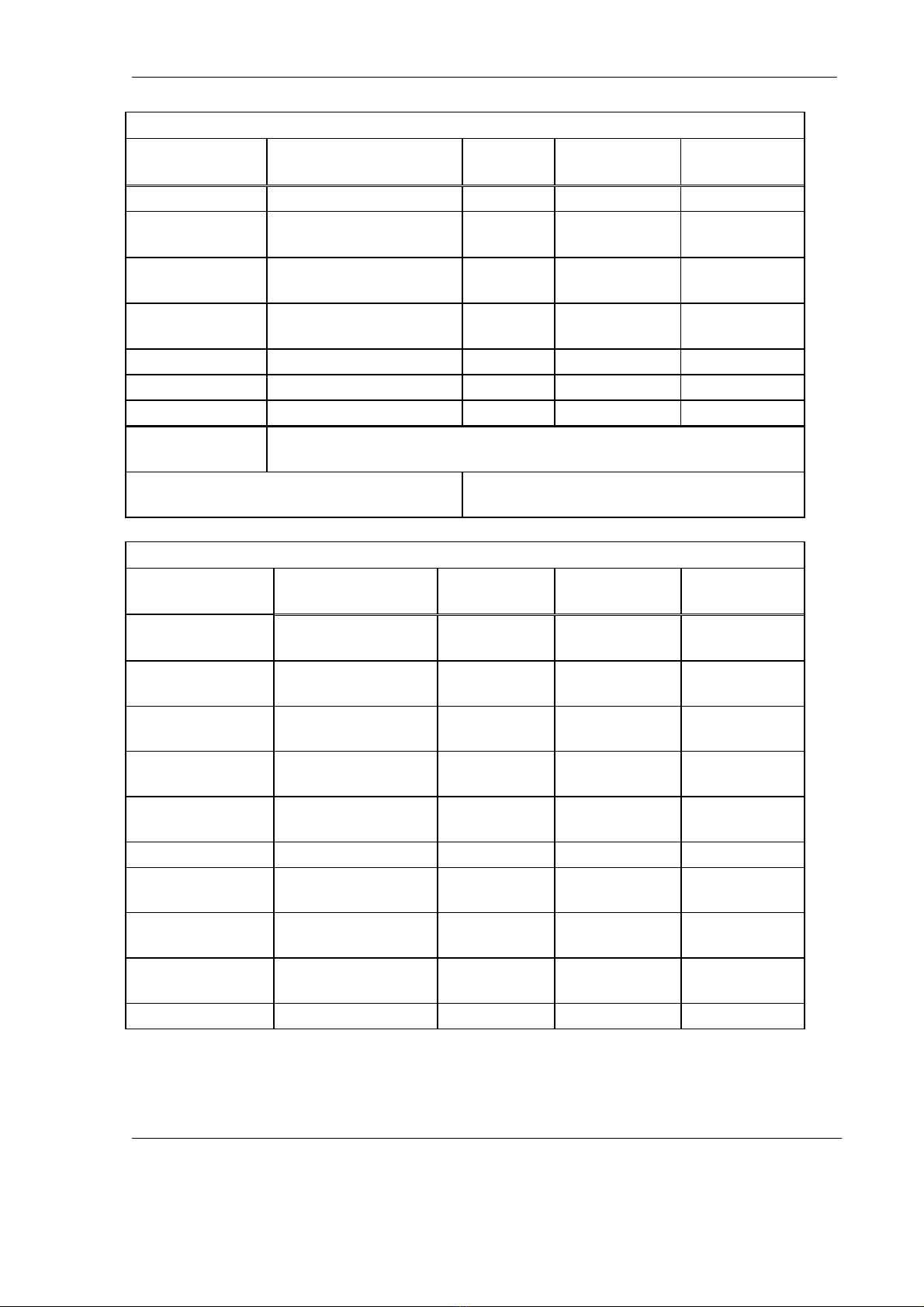
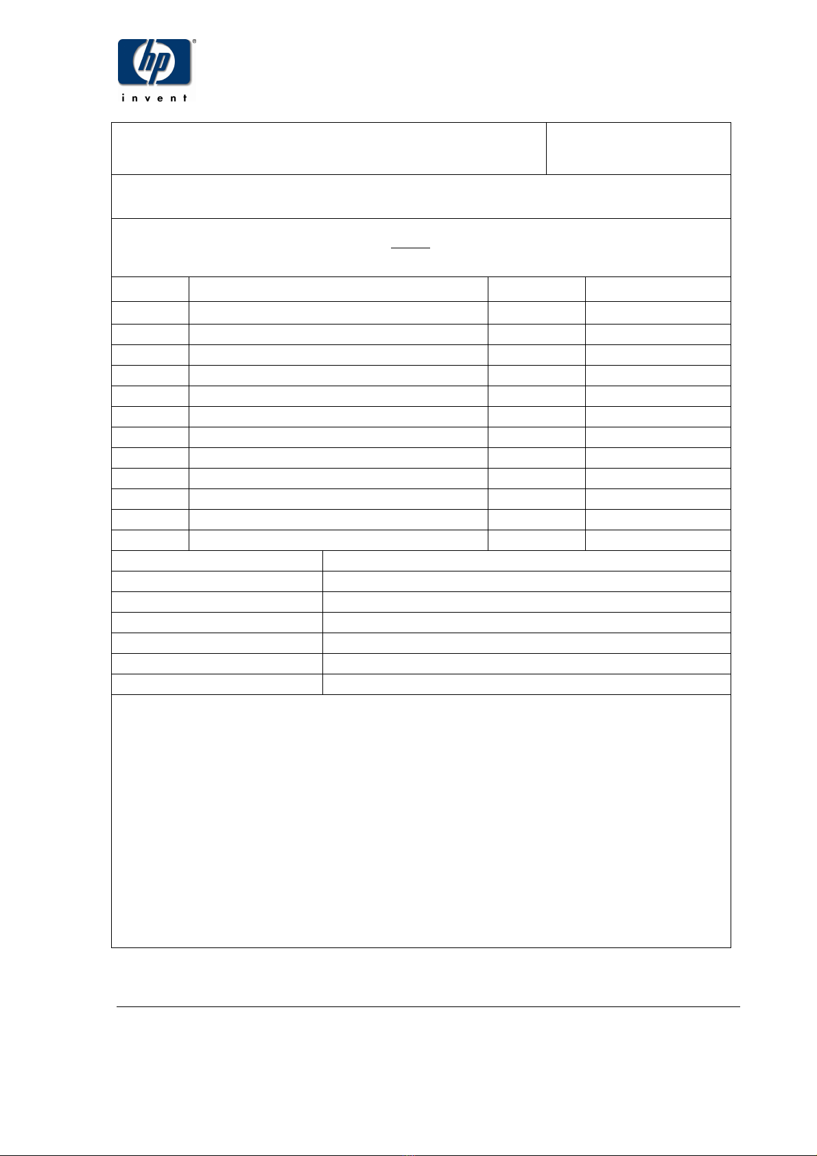
proprietary and confidential page 2 of 3
•hp x2100 Pentium IV PC with software version 5.0 (P/N
EAS-1471-51), for press S/N 11200803 and up:
The software includes hp indigo RIP version 5.0, hp indigo yours truly
designer version 5.0, and hp indigo yours truly express version 5.0.
The software currently supports IndigoServe version 1.0.
The HP 2100 computer does not have an ISA slot; Therefore the
POPCORN cannot be mounted on this computer.
An EPU (the replacement of the UCB) was designed to allow the
mounting of a POPI II (the replacement of POPCORN) in the press.
The POPI II communicates with the computer via the on board Ethernet
port on the motherboard.
The VCORN I does not fit in the new HP 2100 computer. A new
modified VCORN I was designed to fit in the computer.
The hp indigo press arrives with a new hp monitor. This monitor includes
a new external power supply.
An ORB media 2.2 GB replaces the old Jaz drive.
For more details Refer to T/N #595
•1 HP vacuum pump motor (P/N MMA-0101-05):
This improvement will eliminate overheating of the vacuum pump motor.
•New pulley for 60HZ presses:
The new vacuum pump pulley is part of the accessory kit and will be
installed in presses operating at 60Hz frequency. This pulley is
compatible to 60 Hz cycle and enable the vacuum pump motor to work
efficiently. This kit should be discarded in any other case. Refer to the
attached document for the installation procedure.
3. Instructions
The following are press installation important notes:
•The new vacuum pump pulley installation kit (P/N MKT-0102-01) should
be used in presses operating at 60Hz frequency.
•The HP monitor is supplied with an external power supply that should be
installed during the press installation.
4. Prerequisites
N/A

proprietary and confidential page 3 of 3
5. Documents
•New Baldor parameters (attached)
•New vacuum pump pulley installation instructions
•Spare parts list
•EPU wiring diagram
6. Notes
hp indigo press s2000 serial numbers and configuration are as follows:
•S/N 11200783 - 11200802: Motorola PIII 600MHz PC, SW ver 5.0,
ITT, 1 horse power vacuum pump motor , Vacuum pump pulley for
60 Hz.
•S/N 11200803: hp 2100 PC, EPU, SW ver 5.0, ITT, 1 horse
power vacuum pump motor , Vacuum pump pulley for 60 Hz.

MPS-2224-AI
ITT upgrade Baldor parameters
Changed parameters are marked by a Î
Level 1 Blocks–S/W Ver. 3.12
Block Title Parameter P# Factory
Setting
HP Indigo
Setting
ÎPRESET PRESET SPEEDS #1 1001 0 RPM 1863 RPM
(1859)
PRESET SPEEDS #2 1002 0 RPM 155 RPM
PRESET SPEEDS #3 1003 0 RPM 0 RPM
PRESET SPEEDS #4 1004 0 RPM 0 RPM
PRESET SPEEDS #5 1005 0 RPM 0 RPM
PRESET SPEEDS #6 1006 0 RPM 0 RPM
PRESET SPEEDS #7 1007 0 RPM 0 RPM
PRESET SPEEDS #8 1008 0 RPM 0 RPM
PRESET SPEEDS #9 1009 0 RPM 0 RPM
PRESET SPEEDS #10 1010 0 RPM 0 RPM
PRESET SPEEDS #11 1011 0 RPM 0 RPM
PRESET SPEEDS #12 1012 0 RPM 0 RPM
PRESET SPEEDS #13 1013 0 RPM 0 RPM
PRESET SPEEDS #14 1014 0 RPM 0 RPM
PRESET SPEEDS #15 1015 0 RPM 0 RPM
ACCEL/DECEL ACCEL TIME #1 1101 3.0 SEC 1.3 SEC
DECEL TIME #1 1102 3.0 SEC 3.7 SEC
S-CURVE #1 1103 0 % 0 %
ACCEL TIME #2 1104 3.0 SEC 3.0 SEC
DECEL TIME #2 1105 3.0 SEC 3.0 SEC
S-CURVE #2 1106 0 % 0 %
JOG
SETTINGS
JOG SPEED 1201 200 RPM 155 RPM
JOG ACCEL TIME 1202 3.0 SEC 3.0 SEC
JOG DECEL TIME 1203 3.0 SEC 0 SEC
JOG S- CURVE TIME 1204 0 % 0 %
KEYPAD
SETUP
KEYPAD STOP KEY 1301 REMOTE ON REMOTE ON
KEYPAD STOP MODE 1302 REGEN REGEN
KEYPAD RUN FWD 1303 ON ON
Proprietary and Confidential MPS-2224-AI Rev 00 Page 41 of 55

MPS-2224-AI
Level 1 Blocks–S/W Ver. 3.12
Block Title Parameter P# Factory
Setting
HP Indigo
Setting
KEYPAD RUN REV 1304 ON OFF
KEYPAD JOG FWD 1305 ON ON
KEYPAD JOG REV 1306 ON OFF
LOC. HOT START 1307 OFF OFF
ÎINPUT OPERATING MODE 1401 KEYPAD SERIAL
(15SPD)
ÎCOMMAND SELECT 1402 +/-10 VOLTS SERIAL
(+/-10V)
ANA CMD INVERSE 1403 OFF OFF
ANA CMD OFFSET 1404 0.0 % 0.0 %
ANA 2 DEADBAND 1405 0.00 V 0.00V
ANA 1 CUR LIMIT 1406 OFF OFF
OUTPUT OPTO OUTPUT #1 1501 READY READY
OPTO OUTPUT #2 1502 ZERO
SPEED ZERO
SPEED
OPTO OUTPUT #3 1503 AT SPEED AT SPEED
OPTO OUTPUT #4 1504 FAULT FAULT
ZERO SPD SET PT 1505 200 RPM 1 RPM
AT SPEED BAND 1506 100 RPM 1000 RPM
SET SPEED 1507
Rated Motor
Speed
1 RPM
ANALOG OUT #1 1508 ABS SPEED ABS SPEED
ANALOG OUT #2 1509
MOTOR
CURRENT MOTOR
CURRENT
ANALOG #1 SCALE 1510 100 % 100 %
ANALOG #2 SCALE 1511 100 % 100 %
POSITION BAND 1512 CALC 3
ÎVECTOR
CONTROL
CTRL BASE SPEED 1601 CALC 1480 RPM
(1500 RPM)
FEEDBACK FILTER 1602 CALC 5
FEEDBACK ALIGN 1603 FORWARD FORWARD
ÎCURRENT PROP
GAIN
1604 20 10
(35)
ÎCURRENT INT GAIN 1605 50 13
(16)
Proprietary and Confidential MPS-2224-AI Rev 00 Page 42 of 55

MPS-2224-AI
Level 1 Blocks–S/W Ver. 3.12
Block Title Parameter P# Factory
Setting
HP Indigo
Setting
SPEED PROP GAIN 1606 10 20
ÎSPEED INT GAIN 1607 1.00 HZ 3
(0.9)
ÎSPEED DIFF GAIN 1608 0 3
(5)
ÎPOSITION GAIN 1609 CALC 25
(0)
SLIP FREQUENCY 1610 CALC 3.33 HZ
STATOR R1 1611 CALC 1.7
STATOR X1 1612 CALC 3
LEVEL 2
BLOCK
ENTERS LEVEL 2 MENU
PRESS ENTER FOR PROGRAMMING
EXIT
Exit programming mode and return to
display mode
Level 2 Blocks– S/W Ver. 3.12
Block Title Parameter Parameter # Factory
Setting
HP Indigo
Setting
OUTPUT LIMITS OPERATING
ZONE
2001 STD CONST
TQ
STD VAR TQ
MIN OUTPUT
SPEED
2002 0 RPM 0 RPM
MAX OUPUT
SPEED
2003 Rated Motor
Speed
2000 RPM
PK CURRENT
LIMIT
2004 PK Control
Rating
4.2 A
PWM
FREQUENCY
2005 2.5 KHz 2.9 KHZ
CUR RATE LIMIT 2006 0.000 SEC 0.000 SEC
CUSTOM UNITS DECIMAL
PLACES
2101 5 5
VALUE AT SPEED 2102
00000/010000
RPM
0./1000 RPM
UNITS OF
MEASURE
2103 **** ****
PROTECTION OVERLOAD 2201 FOLDBACK FOLDBACK
Proprietary and Confidential MPS-2224-AI Rev 00 Page 43 of 55

MPS-2224-AI
Level 2 Blocks– S/W Ver. 3.12
Block Title Parameter Parameter # Factory
Setting HP Indigo
Setting
EXTERNAL TRIP 2202 OFF OFF
LOCAL ENABLE
IMP
2203 OFF OFF
FOLLOWING
ERROR
2204 OFF ON
TORQUE
PROVING
2205 OFF OFF
MISCELLANEOUS RESTART
AUTO/MAN
2301 MANUAL AUTOMATIC
RESTART
FAULT/HR
2302 0 0
RESTART DELAY 2303 0 SEC 0 SEC
FACTORY
SETTINGS
2304 NO NO
ÎHOMING SPEED 2305 100 RPM 970 RPM
(0 RPM)
ÎHOMING OFFSET 2306 Encoder
Counts 12750
(0)
SECURITY SECURITY STATE 2401 OFF OFF
CONTROL ACCESS
TIMEOUT
2402 0 SEC 0 SEC
ACCESS CODE 2403 9999 9999
MOTOR DATA MOTOR
VOLTAGE
2501 Factory Set 230 V
MOTOR RATED
AMPS
2502 Factory Set 1.9 A
MOTOR RATED
SPD
2503 1750 RPM 1400 RPM
MOTOR RATED
FREQ
2504 60.0 HZ 50 HZ
MOTOR MAG
AMPS
2505 CALC 0.8 A
ÎENCODER
COUNTS
2506 1024 PPR 157 PPR
(472)
RESOLVER
SPEEDS
2507 0 SPEED 0 SPEED
CALC PRESETS 2508 NO NO
Proprietary and Confidential MPS-2224-AI Rev 00 Page 44 of 55

MPS-2224-AI
Level 2 Blocks– S/W Ver. 3.12
Block Title Parameter Parameter # Factory
Setting HP Indigo
Setting
BRAKE ADJUST RESISTOR OHMS 2601 Factory Set 14 OHM
RESISTOR
WATTS
2602 Factory Set 400 W
DC BRAKE
CURRENT
2603 0% 0%
PROCESS
CONTROL PROCESS
FEEDBACK
2701 NONE NONE
PROCESS
INVERSE
2702 OFF OFF
SETPOINT
SOURCE
2703 SETPOINT
CMD SETPOINT
CMD
SETPOINT
COMMAND
2704 0.0 % 0.0 %
SET PT ADJ LIMIT 2705 10.0% 10.0%
PROCESS ERR
TOL
2706 10 % 10 %
PROCESS PROP
GAIN
2707 0 0
PROCESS INT
GAIN
2708 0.00 HZ 0.00 HZ
PROCESS DIFF
GAIN
2709 0 0
FOLLOW I:O
RATIOP
2710 1:1 1:1
MASTER
ENCODER
2712 1024 PPR 1024 PPR
COMMUNI-
CATIONS
PROTOCOL 2801 RS-232 ASCII
RS-232
ASCII
BAUD RATE 2802 9600 9600
DRIVE ADDRESS 2803 0 0
Proprietary and Confidential MPS-2224-AI Rev 00 Page 45 of 55

MPS-2224-AI
Level 2 Blocks– S/W Ver. 3.12
Block Title Parameter Parameter # Factory
Setting HP Indigo
Setting
AUTO-TUNING CALC PRESETS CALC NO NO
NEVER
CHANGE!
CAUTION
NEVER CHANGE AUTO-TUNING IN ANY CIRCUMSTANCE
Any interference in this parameter may cause fatal damage to the machine.
LEVEL 1
BLOCK
Enters Level 1 Menu
PRESS ENTER FOR
PROGRAMMING EXIT Exit programming mode and return to display
mode
Proprietary and Confidential MPS-2224-AI Rev 00 Page 46 of 55

Proprietary and Confidential filename MKT_0102_AI_00.doc page 1 of 10
Date: 20 Jun 02 MKT-0102-AI
hp indigo press s2000
Subject: Pulley replacement only for presses operating at 60Hz
frequency
rev rev description date name
00 initial document 20 Jun 02 Meir Kormian
responsible reviewer: Meir Kormian
en
g
ineerin
g
approved b
y
: Moshe Zilberstein
R & D approved b
y
: Shlomo Harush
service approved b
y
: Aharon Lubelski
documentation mana
g
er: Ronit Shu
g
al
written b
y
: William Easle
y
confi
g
uration control: Charles Mar
gy
Hewlett-Packard Company
Indigo Division
Kiryat Weizmann
P.O. Box 150
Rehovot 76101 Israel
©Copyright Hewlett-Packard Company, 2002. All rights reserved.
CONFIDENTIALITY NOTICE
This document contains valuable trade secrets and confidential information of Hewlett-Packard
Company. Nothing herein may be copied, reproduced or distributed in any form or medium, or
disclosed to any third party in any manner, without prior written authorization of Hewlett-Packard
Company. The copyright notice, which appears in this document, is purely precautionary and shall
not be deemed to constitute publication or intent to publish, in whole or in part.

Proprietary and Confidential MKT-0102-AI Rev 00 page 2 of 10
Contents
1. Purpose ...................................................................................................................3
2. Prerequisites............................................................................................................3
3. Estimated installation time .......................................................................................3
4. Pre-installation .........................................................................................................3
5. Procedure ................................................................................................................3
Disassembling the press ....................................................................................................... 3
Removing the old pulley ........................................................................................................ 4
Installing the new pulley ........................................................................................................ 5
6. Test procedure.........................................................................................................9
7. Parts list ...................................................................................................................9
8. Materials disposition ................................................................................................9
9. Attached documents ................................................................................................9
List of figures
Figure 1 Compressor floor assembly (shown installed) ................................................4
Figure 2 Tools for loosening the motor mounts..............................................................4
Figure 3 Removal of vacuum/blower pump pulley (shown uninstalled for clarity)..........5
Figure 4 Assembly and installation of the pulley on the vacuum/blower pump..............5
Figure 5 Positioning of the outer pulley relative to the inner pulley................................6
Figure 6 Placement of the straight edge ........................................................................6
Figure 7 Touching the motor pulley................................................................................7
Figure 8 Rotation of the motor........................................................................................7
Figure 9 Final alignment of both pulleys.........................................................................7
Figure 10 Checking belt tension.....................................................................................8

Pulley replacement only for presses operating at 60Hz frequency
Proprietary and Confidential MKT-0102-AI Rev 00 Page 3 of 10
1. Purpose
To replace the vacuum/blower pump pulley in hp indigo press s2000 machines
delivered to customers operating with a 60Hz electrical power frequency.
This improvement will install a pulley that is compatible with the 60Hz vacuum/blower
pump motor.
2. Prerequisites
A MultiStream press in proper operating condition.
3. Estimated installation time
One hour
4. Pre-installation
1. Verify, according to the Bill of Materials (BOM), that all the required parts are
included in the kit.
2. Turn off the machine.
3. Disconnect the main power cable.
Danger: The main power cable must remain disconnected throughout the remainder of
this procedure, except where instructed to reconnect it.
5. Procedure
Disassembling the press
1. Remove the paper exit tray.
2. Remove two screws to remove the compressor compartment cover.
Keep the screws.

Pulley replacement only for presses operating at 60Hz frequency
Proprietary and Confidential MKT-0102-AI Rev 00 Page 4 of 10
Removing the old pulley
This procedure is performed without removing the compressor floor assembly from
the press. See Figure 1.
Figure 1 Compressor floor assembly
(shown installed)
1. Loosen the four motor mounting screws using a 13 mm open ring spanner
(P/N MTZ-1173-01). See Figure 2.
Do not remove the screws.
Figure 2 Tools for loosening the motor mounts
2. Slide the motor toward the pump.
3. Remove and keep the belt.
4. Remove the old pulley from the pump shaft as follows (see Figure 3):
VACUUM/BLOWER
PUMP
PUMP PULLEY
(TO BE REPLACED)
VACUUM/BLOWER
PUMP MOTOR
13 mm OPEN
RING SPANNER
3/8 INCH DRIVE
ELBOW
3/8 INCH DRIVE
EXTENSION
3/8 INCH DRIVE
RATCHET

Pulley replacement only for presses operating at 60Hz frequency
Proprietary and Confidential MKT-0102-AI Rev 00 Page 5 of 10
Figure 3 Removal of vacuum/blower pump pulley
(shown uninstalled for clarity)
a. Remove two inset M4 Allen screws from the pump pulley.
b. Insert one of the inset screws into the extraction hole.
This separates the inner and outer pulleys, and releases them from
the shaft.
c. Remove the inner and outer pulleys from the shaft.
d. Remove the dowel. Keep the dowel.
Installing the new pulley
1. Clean the shaft and dowel thoroughly with IPA.
2. Remount the dowel on the shaft. See Figure 4.
683
pulley_assy
Figure 4 Assembly and installation of the pulley on the vacuum/blower pump
INSET M4 ALLEN
SCREWS
(2 PLACES)
EXTRACTION
HOLE
DOWEL
INNER PULLEY
OUTER PULLEY
VACUUM/BLOWER
PUMP
VACUUM/BLOWER
PUMP
SHAFT
OUTER PULLEY
INNER PULLEY
INSET ALLEN
SCREWS
DOWEL

Pulley replacement only for presses operating at 60Hz frequency
Proprietary and Confidential MKT-0102-AI Rev 00 Page 6 of 10
3. Mount the new outer pulley on the shaft. See Figure 4.
4. Align the new inner pulley with the dowel. See Figure 4.
Mount it on the shaft.
5. Fit the outer pulley over the inner pulley. See Figure 5.
Ensure that their relative positions are correct.
Figure 5 Positioning of the outer pulley relative to the inner pulley
The non-threaded half-hole on the outer pulley must be positioned opposite
the threaded half-hole on the inner pulley. These two half-holes form the
extraction hole. See Figure 5.
6. Insert the two inset M6 Allen screws. Do not tighten the screws at this stage.
7. Remount the belt on both the pump and motor pulleys.
8. Align the pump pulley with the motor pulley as follows:
a. Hold a straight-edge flat against the back surface of the pump pulley.
See Figure 6.
Figure 6 Placement of the straight edge
b. Slide the pulley along its shaft until the straight-edge touches the
motor pulley. See Figure 6 and Figure 7.
INSET SCREW HOLE
(2 PLACES)
EXTRACTION
HOLE
NON-THREADED
HALF-HOLE
THREADED
HALF-HOLE
THREADED
HALF-HOLE
NON-THREADED
HALF-HOLE
SLIDE PULLEY
WITH STRAIGHT
EDGE ALONG
SHAFT
FLAT AGAINST
BACK SURFACE
STRAIGHT EDGE
NOT TOUCHING
MOTOR PULLEY PUMP
PULLEY
MOTOR
PULLEY STRAIGHT EDGE
BELT

Pulley replacement only for presses operating at 60Hz frequency
Proprietary and Confidential MKT-0102-AI Rev 00 Page 7 of 10
align_p ulle ys_2
Figure 7 Touching the motor pulley
c. Rotate the motor on its base until the straight-edge makes full contact
across the back surface of the motor pulley (from one side to the
other). See Figure 8 and Figure 9.
align _pulle y s_ 3
Figure 8 Rotation of the motor
alig n_pu lle ys _4
Figure 9 Final alignment of both pulleys
FLAT AGAINST
BACK SURFACE
ROTATE THE
MOTOR ON
ITS BASE
PUMP
MOTOR
SLIDE MOTOR
UNTIL CORRECT
BELT TENSION IS
ACHIEVED.
FLAT AGAINST BACK
SURFACE OF BOTH
PULLEYS
MOTOR PUMP
PULLEY NOT IN
CONTACT WITH
STRAIGHT EDGE
HERE.
STRAIGHT EDGE
TOUCHES MOTOR
PULLEY HERE
MOTOR
STRAIGHT EDGE
BELT

Pulley replacement only for presses operating at 60Hz frequency
Proprietary and Confidential MKT-0102-AI Rev 00 Page 8 of 10
9. Keep the straight-edge in full contact across the back surfaces of both
pulleys.
Slide the motor until the correct tension is achieved in the belt. See Figure 9.
10. Check the belt tension while maintaining pulley alignment by pressing down
on the middle of the belt with a force of about 1 kg (2 lb). See Figure 10.
The belt will displace about 10 mm (1/2 inch) when the correct tension is
achieved.
Caution: Ensure correct belt tension for proper pump operation. Too much tension
damages the shaft bearings. Too little tension causes the belt to slip and wear.
CAPRIVAC
Figure 10 Checking belt tension
11. Tighten the four motor mounting screws using the 13 mm open ring spanner
(P/N MTZ-1173-01).
12. Tighten the two inset screws in the pump pulley.
MOTOR
MOTOR
MOUNTING
SCREWS
(4 PLACES)
PUMP
INSET ALLEN
SCREWS
EXTRACTION
HOLE

Pulley replacement only for presses operating at 60Hz frequency
Proprietary and Confidential MKT-0102-AI Rev 00 Page 9 of 10
6. Test procedure
1. Connect the main power cable.
2. Turn on the machine.
3. Bring the machine to Standby.
4. Activate the pump from the MMI as follows:
a. From the Diagnostics menu select Elements and click the Elements
tab.
b. For the Substrate category, click Vac. Pump.
The pump begins to operate.
5. Verify that the motor and pulley are working properly and that there are no
strange noises.
6. Click Vac. Pump again in the MMI to turn off the pump.
7. If the motor and the pulley are working properly, reinstall the compressor
compartment cover using the original two screws.
8. Reinstall the paper exit tray.
9. If the motor or pulley is not working properly, perform the following:
a. Turn off the machine.
b. Disconnect the main power cable.
Danger: The main power cable must remain disconnected while working on the pump or
motor.
c. Reinstall the pulley and belt per the procedure in this kit.
d. Reverify that the motor and pulley are working properly per steps 1
through 6 above.
e. Reinstall the compressor compartment cover using the original two
screws.
f. Reinstall the paper exit tray.
7. Parts list
N/A
8. Materials disposition
Discard old pump pulley.
9. Attached documents
N/A

Proprietary and Confidential File Name: MKT_0102_AI_00.doc page 10 of 10
Please answer the following questions:
How much time did you spend on installation?
How much time did you spend on the following?
pre-installation adjustments
installation procedure
testing and final adjustments
Were the instructions in this Option sufficiently clear?
Were there sufficient, easy-to-understand drawings?
Did you need any additional tools or accessories?
Were there any specific difficulties or problems in implementing this Option?
General remarks:
Thank you for your cooperation
Option feedback
Complete this form immediately after implementation of the Option. Send the fax to:
Att:
Fax:
Customer Support
Meir Kormian
Hewlett-Packard Company, Indigo Division
(972)-8-9385696
Date (mm/dd/yy):
Kit number: MKT-0102-AI
Machine serial number:
Customer name:
Country/state:
Technician name:
Tel:
Fax:

hp indigo press s2000 spare parts list
P/N Item
MPX-4662-51 RR Sub Assembly
MPX-4622-51 Wetting Roller Assembly
MPX-4656-51 Reverse Roller Assembly
MPX-0953-31 RR Geer Assembly
MPX-0959-31 WR Geer Assembly
MEN-1010-01 Encoder (90 cm cable)
MCL-0368-01 Encoder Coupling
MPX-7926-01 Spring External First Transfer
MPX-4573-51 Disengage Scorotron Assembly
EAS-1109-51 Baldor motor control unit
MPX-5425-52 W/H Main Assembly
EBE-2305-53 WHIF 2 board
MMA-0101-05 1 HP Vacuum pump motor
Table of contents
Other HP Power Tools manuals
Popular Power Tools manuals by other brands

Ryobi
Ryobi ERT-1150V Owner's operating manual

SUHNER
SUHNER LBC 16-TOP Technical document

EINHELL Bavaria
EINHELL Bavaria BPS 800 E operating instructions

Sparky Group
Sparky Group BR 9,6E instruction manual

Everwin
Everwin PN57 Series Operation and maintenance manual

Gage Bilt
Gage Bilt GB3585A Original instructions