manuals.online logo
Brands
  1. Home
  2. •
  3. Brands
  4. •
  5. HP
  6. •
  7. Touch Terminal
  8. •
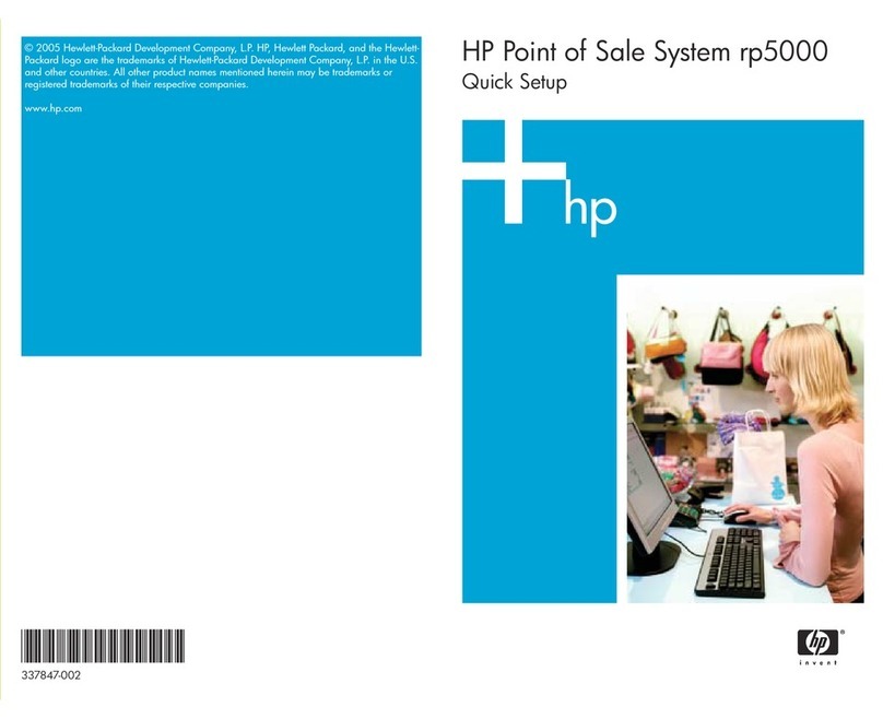
  9. HP Rp5000 - Point of Sale System Setup guide

HP Rp5000 - Point of Sale System Setup guide

Notes:
⌧ Original Spare
 Modified Spare
REQUIREMENT:
For customers in countries/regions with RoHS legislation* (e.g. EU,
China, etc.) restricting the use of hazardous substances in electrical
equipment.
The use of the Original Spare part is regulated by RoHS legislation. If your
unit contains a part that is labelled with the Modified Spare number, the
Modified Spare must be ordered as the replacement part.
If your unit contains a part that is labelled with the Original Spare number,
please order the Original Spare as the replacement part. In this case either the
Original Spare or the Modified Spare may be shipped which will not affect
performance or functionality of the unit.
*Directive 2002/95/EC restricts the use of lead, mercury, cadmium, hexava-
lent chromium, PBBs and PBDEs in electronic products. Countries/regions
outside the EU, e.g. China, are introducing similar legislation. References to
‘RoHS legislation’ means requirements of Directive 2002/95/EC or similar
substance restrictive legislation enacted by any country/region outside the
EU. or similar substance restrictive legislation enacted by any country/
region outside the EU.
System Unit
1 Chassis assembly not spared
2 Power supply, 185W, PFC 308617-001*⌧
397124-001 
3 Computer access panel 280164-001*⌧
431921-001 
4 Front bezel assembly 346947-001 
Mass Storage Devices
1Diskette drive, w/out bracket, with mounting screws 333505-001*⌧
392415-001 
240 GB\5400 RPM PATA Hard drive 411960-001 
+80 GB\7200 RPM PATA Hard drive 411961-001 
348X CD-ROM drive with mounting screws 340430-001*⌧
397130-001 
+48/32/48X CD-RW Drive 395272-001 
+48/32/48+16X CD/DVD Drive 405425-001 
+16/40X DVD ROM Drive 325313-001*⌧
405761-001 
+16X DVD+/-RW Drive 405760-001 
+Not shown
Standard and Optional Boards
1 System board with alcohol pad and thermal grease 337070-001*⌧
350325-001*⌧
398878-001 
2Backplane (riser board without tray) 323090-001*⌧
398778-001 
3 Powered USB card 337069-001*⌧
398879-001 
Memory Modules
4 128 MB 333 MHz DDR, PC3200 314795-001*⌧
+ 256 MB 333 MHz DDR, PC3200 314793-001*⌧
407309-001 
+ 512 MB 333 MHz DDR, PC3200 314796-001*⌧
407310-001 
+ 1.0 GB 333 MHz DDR, PC3200 314794-001*⌧
407311-001 
Intel Processors with alcohol pad and thermal grease
+ Celeron 2.0 GHz/400 MHz processor 346949-001*⌧
417346-001 
Celeron 2.5 GHz/400 MHz processor 344056-001*⌧
417347-001 
5 Pentium 2.0 GHz/400 MHz processor 309578-001*⌧
417348-001 
Pentium 2.4 GHz/533 MHz processor 288689-001*⌧
417345-001 
Pentium 2.8 GHz/533 MHz processor 305051-001*⌧
417349-001 
Other Cards
+ nVidia Quadro4 100 NVS, PCI, 32 MB, ATX bkt 322892-001*⌧
+ Wireless LAN PCI Adapter (802.11) wo/cable
-001 = Rest of World w/antenna
-002 = North America w/antenna
332963-001*⌧
391866-001 
391866-002 
nVidia Quadro4 280 NVS, PCI, 64 MB 351384-001*⌧
398686-001 
+ Modem, v.92, PCI 239411-001*⌧
398661-001 
+Not shown
* See Requirement below
© 2003, 2004, 2006 Hewlett-Packard Development Company,
L.P.
The information contained herein is subject to change
without notice.
HP and the HP logo are trademarks of Hewlett-Packard
Development Company, L.P.
Intel, Pentium, and Celeron are trademarks of Intel
Corporation in the U.S. and other countries.
All other product names mentioned herein may be
trademarks of their respective companies.
HP shall not be liable for technical or editorial errors or
omissions contained herein. The information in this document
is provided “as is” without warranty of any kind and is subject
to change without notice. The warranties for HP products are
set forth in the express limited warranty statements
accompanying such products. Nothing herein should be
construed as constituting an additional warranty.
First Edition, August 2003
Fourth Edition, June 2006
Document Number
344318-004
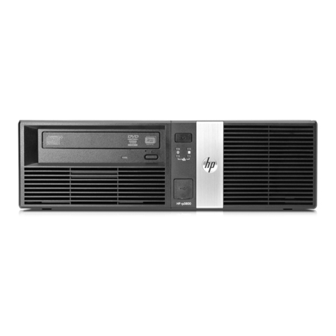
HP Point of Sale System rp5000
Illustrated Parts Map
Small Form Factor Chassis
Cables
1 Diskette drive cable (168999-005) 337244-001 
2UATA data cable, single device 346948-001*⌧
407301-001 
+UATA data cable, single device for ODD or second
HDD
337247-001*⌧
407302-001 
3Power switch/LED cable with switch holder 337243-001*⌧
407303-001 
+Wireless LAN antenna (use with 332963-001) 333365-001*⌧
4Powered USB card cable (use with 337069-001 or
398879-001)
289574-001*⌧
407306-001 
+Not shown
*See Requirement below
Miscellaneous Parts
1 Front bezel assembly 346947-001 
+ Diskette drive bay bezel blank 337019-001 
2 5.25” Bay bezel blank 335937-001 
3 Speaker with housing 337249-001*⌧
398777-001 
4 Heatsink with fan, thermal grease and alcohol pad 336580-001*⌧
407307-001 
5 Chassis fan 342685-001*⌧
407304-001 
+ System board tray with 2nd serial port 353055-001*⌧
407305-001 
+ Mouse, 2-Button, PS/2 with scroll wheel 323614-001*⌧
390937-001 
+ Mouse, 2-Button, optical 390938-001 
+ Misc screw kit, includes: 337237-001 
M3 x 5mm, hitop (247348-001) 4 ea
#6-32 x .250, hitop (192308-001) 8 ea
#6-32 x .250, pan head (101517-067) 3 ea
#6-32 x .312, hitop (192308-002) 4 ea
#6-32 x .312, pan head (101346-068) 2 ea
#6-19 x .315, T15 head, Plastite (331310-001) 2 ea
+ External USB Flash Drive, 64 MB 331465-001*⌧
+ External USB Flash Drive, 128 MB 331466-001*⌧
+ Powered serial port cover 353054-001 
+ Real-time-clock battery 153099-001 
+Not shown
*See Requirement below
Keyboards (not illustrated)
PS/2, Basic 346984-001*⌧
382925-xxx 
Danish -081 Italian -061
French -051 LA Spanish -161
French Arabic -DE1 Spanish -071
French Canadian -121 Swiss -111
Greek -041 United Kingdom -031
Hebrew -BB1 U.S. -001
International** -B31
+Not shown
*See Requirement below
Heat Sink Removal - Early Models
Jumper Settings
System Board Connectors and Jumpers (position of some untitled components may vary in location)
AGP 1 AGP slot (for powered USB card only) J12V_SEL 1** 12V Jumper for COM 1#
BAT 1 Battery J12V_SEL 2** 12 V Jumper for COM 2#
C_FAN 1 CPU fan J12V_SEL 3** 12 V Jumper for COM 3#
COM 2 Flying serial port J12V_SEL 4** 12 V Jumper for COM 4#
CONN1 Main power (20 pin) JBAT 1* CMOS jumper
DDR 1 Memory socket 1 JPW 1 CPU regulator power (4 pin)
DDR 2 Memory socket2 JPWD 1 Password jumper
FLOPPY Diskette drive JUSB1* Signal connector for powered USB
card
F_P 1 Front panel power switch/LED PCI 1 PCI slot 1
J5V_SEL 1** 5V Jumper for COM 1# PRIMARY Primary IDE
J5V_SEL 2** 5V Jumper for COM 2# S_FAN 1 Chassis fan
J5V_SEL 3** 5V Jumper for COM 3# SECONDARY Secondary IDE
J5V_SEL 4** 5V Jumper for COM 4# U3 Processor socket
*Default = pins 1-2
**Default = pins 2-3
#See instructions below
System hardware Interrupts
IRQ System Function IRQ System Function
0Timer Interrupt 8 Real-Time Clock
1Keyboard 9 Unused
2Interrupt Controller Cascade 10 Serial Port (COM C)
3Serial Port (COM B) 11 Unused, available for PCI
4Serial Port (COM A) 12 Mouse
5Serial Port (COM D) 13 Coprocessor
6Diskette Drive 14 Primary ATA (IDE) Controller
7Parallel Port (LPT 1) 15 Secondary ATA (IDE) Controller
Computer Diagnostic LEDs (on front of computer)
LED Color LED Activity State/Message
Power Green On (S0) Computer on
Power Green 1 blink every 1 second (S1) Suspend Mode
Power Green 1 blink every 1 second (S3) Suspend to RAM
Power Green Off (S4) Suspend to Disk (if applicable)
Power Clear Off (S5) Computer off
Power Red On Power Supply failure
Power Red* 2 blinks 1 second apart CPU thermal shutdown
Power Red On CPU not installed
Power Red* 1 blink every 2 seconds Power supply overload ( crow bar)
Power Red* 5 blinks 1 second apart No memory
Power Red* 6 blinks 1 second apart No graphics
Power Red* 7 blinks 1 second apart System board failure (detected prior to video)
Power Red* 8 blinks 1 second apart Invalid ROM
Hard Drive Green Blinking Hard drive activity
*Blinking codes are repeated after a 2 second pause.
Keyboard Diagnostic LEDs, PS/2 Keyboards Only
LED Color LED Activity State/Message
Num, Caps,
Scroll Lock
Green On (Rising Tone) ROM reflashed successfully
Num Lock Green On ROMPaq diskette not present, is bad, or drive
not ready.*
Caps Lock Green On Enter password.
Num, Caps,
Scroll Lock
Green Blink On in sequence, one at a
time - N, C, SL
Keyboard locked in network mode
* Insert valid ROMPaq diskette in drive A. Turn power switch off, then on to reflash ROM. If ROM flash is successful, all
three keyboard LEDs will light up, and you will hear a rising tone series of beeps. Remove diskette and turn power off,
then on to restart the computer. For more information about flashing the ROM, refer to the Troubleshooting guide.
Computer Setup (F10) Utility Features (not all features may be available)
File
System Information
About
Set Time and date
Save to Diskette
Restore From Diskette
Set defaults and Exit
Ignore Changes and Exit
Save Changes and Exit
Storage Device Configuration
Options
IDE DPS Self-Test
Controller Order
Boot Order
Security
Setup Password
Power-On Password
Password Options
Smart Cover
Smart Sensor
DriveLock
Master Boot Record Security
Save Master Boot Record
Restore Master Boot Record
Device Security
Network Service Boot
System IDs
Advanced Power-On Options
Onboard devices
PCI Devices
Bus Options
Device Options
PCI VGA Configuration
Note: See Computer Setup (F10) Utility Guide on the Documentation Library CD.
Clearing CMOS
The computer's configuration (CMOS) may occasionally be corrupted. If it is, it is necessary to clear the CMOS
memory using jumper JBAT 1.
To clear and reset the configuration, perform the following procedure:
1. Prepare the computer for disassembly.
ÄCAUTION: The power cord must be disconnected from the power source before pushing the Clear CMOS
Button (NOTE: All LEDs on the board should be OFF). Failure to do so may damage the system board
2. Remove the access panel.
3. Move the CMOS jumper JBAT 1 from pins 1-2 to pins 2-3.
4. After 60 seconds, move the jumper back to pins 1-2.
5. Replace the access panel.
6. Turn the computer on and run F10 Computer Setup (Setup-utility) to reconfigure the system.
Disabling or Clearing the Power-On and Setup Passwords
1. Turn off the computer and any external devices, and disconnect the power cord from the power outlet.
2. Remove the access panel.
3. Locate the header and jumper labeled JPWD1.
4. Remove the jumper from pins 1 and 2. Place the jumper over pin 2 only, in order to avoid losing it.
5. Replace the access panel.
6. Plug in the computer and turn on power. Allow the operating system to start.
NOTE: Placing the jumper on pin 2 clears the current passwords and disables the password features.
7. To re-enable the password features, repeat steps 1-3, then replace the jumper on pins 1 and 2.
8. Repeat steps 5-6, then establish new passwords.
Refer to the Computer Setup (F10 Setup) instructions to establish new passwords.
Powered Serial Ports (Powered serial ports ship with blue plastic caps on them for easy identification)
Pin No. RS-232
Signal Direction Notes
1 DCD Input May be configured for either 0V or +12V.
2 RxD Input
3 TxD Output
4 DTR Output
5 SG Signal gnd
6 DSR Input
7 RTS Output
8 CTS Input
9 RI Input May be configured for either 0V or +5V.

Other manuals for Rp5000 - Point of Sale System

13

Other HP Touch Terminal manuals

HP Engage Go Convertible System Operating and maintenance manual

HP

HP Engage Go Convertible System Operating and maintenance manual

HP RP7 Model 7800 Manual

HP

HP RP7 Model 7800 Manual

HP ap5000 Setup guide

HP

HP ap5000 Setup guide

HP ap5000 Specification sheet

HP

HP ap5000 Specification sheet

HP rp5800 Assembly instructions

HP

HP rp5800 Assembly instructions

HP rp5800 Manual

HP

HP rp5800 Manual

HP RP7 Model 7800 Operating and maintenance manual

HP

HP RP7 Model 7800 Operating and maintenance manual

HP RP7 Model 7800 User manual

HP

HP RP7 Model 7800 User manual

HP Rp5000 - Point of Sale System User manual

HP

HP Rp5000 - Point of Sale System User manual

HP Engage Go Mobile System Assembly instructions

HP

HP Engage Go Mobile System Assembly instructions

HP RP7 Model 7800 Setup guide

HP

HP RP7 Model 7800 Setup guide

HP ap5000 User instructions

HP

HP ap5000 User instructions

HP 2624 User manual

HP

HP 2624 User manual

HP RP7 Model 7800 User manual

HP

HP RP7 Model 7800 User manual

HP Engage Go 10 User manual

HP

HP Engage Go 10 User manual

HP Engage One Pro User manual

HP

HP Engage One Pro User manual

HP RP7 Model 7800 User manual

HP

HP RP7 Model 7800 User manual

HP Rp5000 - Point of Sale System User manual

HP

HP Rp5000 - Point of Sale System User manual

HP Rp5000 - Point of Sale System Owner's manual

HP

HP Rp5000 - Point of Sale System Owner's manual

HP Rp5000 - Point of Sale System User manual

HP

HP Rp5000 - Point of Sale System User manual

HP 13220 Manual

HP

HP 13220 Manual

HP ElitePOS G1 Installation instructions

HP

HP ElitePOS G1 Installation instructions

HP Engage Go Convertible System User manual

HP

HP Engage Go Convertible System User manual

HP HP700/92 User manual

HP

HP HP700/92 User manual

Popular Touch Terminal manuals by other brands

detekt RDS2500 product manual

detekt

detekt RDS2500 product manual

Appostar Grand POS GP-3464 user manual

Appostar

Appostar Grand POS GP-3464 user manual

VeriFone T650m instruction manual

VeriFone

VeriFone T650m instruction manual

Huawei ETS2225 user guide

Huawei

Huawei ETS2225 user guide

Partner Tech International PT-6200 Service manual

Partner Tech International

Partner Tech International PT-6200 Service manual

Fujitsu TeamPoS 7000 Series user guide

Fujitsu

Fujitsu TeamPoS 7000 Series user guide

Worth Data 701 RF user guide

Worth Data

Worth Data 701 RF user guide

Taxi Butler ONE manual

Taxi Butler

Taxi Butler ONE manual

Mitsubishi Electric GT1020 Series Startup guide

Mitsubishi Electric

Mitsubishi Electric GT1020 Series Startup guide

Inmarsat Wideye Sabre Ranger Series installation guide

Inmarsat

Inmarsat Wideye Sabre Ranger Series installation guide

Perimeter Technology VU-ACD /100 Maintenance Guide

Perimeter Technology

Perimeter Technology VU-ACD /100 Maintenance Guide

Magtek DynaProx Quick installation guide

Magtek

Magtek DynaProx Quick installation guide

Tatung POS85M user manual

Tatung

Tatung POS85M user manual

amber connect Covert T300 quick start guide

amber connect

amber connect Covert T300 quick start guide

NCR RealPOS 25 user guide

NCR

NCR RealPOS 25 user guide

RDM synergy II installation guide

RDM

RDM synergy II installation guide

Beckhoff KL3214 Documentation

Beckhoff

Beckhoff KL3214 Documentation

Omron NT21 Reference manual

Omron

Omron NT21 Reference manual

manuals.online logo
manuals.online logoBrands
  • About & Mission
  • Contact us
  • Privacy Policy
  • Terms and Conditions

Copyright 2025 Manuals.Online. All Rights Reserved.