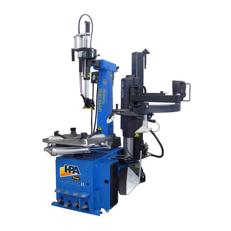
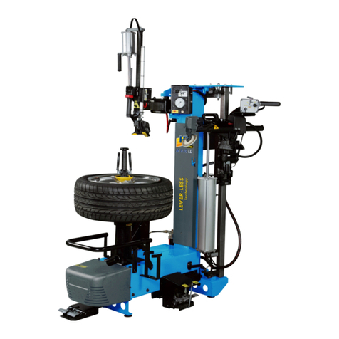
HPA-Faip M 322 User manual

Italiano Manuale d’uso
English Operator’s manual
Français Utilisation et entretien
Deutsch Betriebs und Wartungsanleitung
Español Uso y mantenimiento
Cod. 4-133617C del 11/2017
SMONTAGOMME
TYRE CHANGER
DÉMONTE-PNEU
REIFENMONTIERMASCHIN
DESMONTADORA DE NEUMÁTIC
M 322
www.hpa-faip.it

60 M 322 Operator Manual
TRANSLATION OF ORIGINAL INSTRUCTIONS (ITALIAN)
Copyrighted material. All rights reserved.
The information contained herein may be subject to modifications without prior notice.
Thank you for selecting our tyre changer
SIMPESFAIP
Dear Customer
Thank you for purchasing your SIMPESFAIP Tyre Changer.
Your Tyre Changer has been designed to provide years of safe and dependable service,
as long as it is used and maintained in accordance with the instructions provided in this
manual.
Everyone who will use and/or perform maintenance on the tyre changer must read,
understand and observe all the warnings and instructions provided in this manual, in
addition to being properly trained.
This instruction manual must be considered an integral part of the tyre changer and
kept together with it. However, no information contained in this manual and no device
installed on the tyre changer can replace suitable training, correct operation and careful
evaluation of procedures for working safely.
Always make sure that the tyre changer is in optimal operating conditions. If any malfunc-
tions or probable situations of danger are observed, immediately stop the tyre changer
and resolve the conditions before continuing.
For any question related to the correct tyre changer use or maintenance, contact your
local official SIMPESFAIP dealer.
Yours sincerely,
SIMPESFAIP
USER INFORMATION
User
Name_______________________________________________________________________
User
Address_____________________________________________________________________
Model
Number_____________________________________________________________________
Serial
Number_____________________________________________________________________
Date of
purchase____________________________________________________________________
Date of
installation __________________________________________________________________
Support and spare parts
manager_____________________________________________________________________
Phone
number_____________________________________________________________________
Sales
manager_____________________________________________________________________
Phone
number______________________________________________________________________

M 322 Operator Manual 61
TRAINING CHECK
Qualified Rejected
Safety Precautions
Warning and caution labels
High risk areas and other potential hazards
Operative safety procedures
Maintenance and Performance Checks
Mounting Head Inspection
Adjustment and Lubrication
Clamping
Steel / alloy wheels
Reverse rim wheels
Internal/external clamping with steel clamping grippers
Bead breaking
Standard wheels
Low profile wheels
Demounting
Standard wheels with plastic protectors for head and lever
Correct head position to prevent damage
Bead lubrication when removing the low profile tyres
Reverse rims
Mounting
Standard wheels
Mounting stiff, low profile tyres
Reverse rim wheels
Bead lubrication for correct mounting
Inflating procedure
Safety measures
Lubrication and removal of the valve insert
Tubeless tyre inflation

62 M 322 Operator Manual
Individuals and Dates Trained
_____________________________________________________________________
_____________________________________________________________________
_____________________________________________________________________
_____________________________________________________________________
_____________________________________________________________________
_____________________________________________________________________
_____________________________________________________________________
_____________________________________________________________________
_____________________________________________________________________
_____________________________________________________________________

M 322 Operator Manual 63
Contents
1. GETTING STARTED ................................................................................ 65
1.1 INTRODUCTION ...........................................................................................65
1.1.A. PURPOSE OF MANUAL .................................................................................65
1.2 FOR YOUR SAFETY .....................................................................................65
1.2.A. GENERAL WARNINGS AND INSTRUCTIONS ..............................................66
1.2.B. LABEL POSITIONING .....................................................................................69
1.2.C. ELECTRICAL AND PNEUMATIC CONNECTION ...........................................72
1.2.D TECHNICAL DATA ............................................................................................73
1.2.E. AIR PRESSURE .................................................................................................74
1.3. ADDITIONAL RIM/TYRE INFORMATION ..................................................75
1.4. INTENDED MACHINE USE ........................................................................75
1.5. PERSONNEL TRAINING .............................................................................75
1.6. PRELIMINARY CHECKS..............................................................................76
1.7. DURING USE................................................................................................76
2. SHIPPING, STORAGE AND HANDLING............................................... 76
2.1. UNPACKING.................................................................................................77
3. ASSEMBLY/HANDLING.......................................................................... 77
3.1. HOISTING/HANDLING ...............................................................................79
4. INSTALLATION AREA.........................................................................................79
5. DESCRIPTION OF M 322 ........................................................................ 80
5.1. OPERATOR POSITION.................................................................................81
5.2. MACHINE COMPONENTS (MAIN OPERATING
ELEMENTS OF THE MACHINE) ................................................................81
5.3. OPTIONAL ACCESSORIES..........................................................................83
6. BASIC PROCEDURES - USE ................................................................... 84
6.1. PRELIMINARY CHECKS..............................................................................84
6.2. DECIDING FROM WHICH SIDE OF THE WHEEL THE TYRE MUST BE
DEMOUNTED .....................................................................................................84
6.3. BEAD BREAKING ........................................................................................86
6.4. WHEEL CLAMPING.....................................................................................87
6.5. DEMOUNTING.............................................................................................88
6.6. MOUNTING..................................................................................................90
6.7. APPROVED UHP AND RUN FLAT TYRE DEMOUNTING AND MOUNT-
ING PROCEDURE ...............................................................................................91
6.8. TYRE INFLATION.........................................................................................91
6.8.A. SAFETY REGULATIONS ..................................................................................91
6.8.B. TYRE INFLATION .............................................................................................93
6.8.C. SPECIAL PROCEDURE (FS VERSION)...........................................................94
7. TROUBLESHOOTING ............................................................................. 96
8. MAINTENANCE....................................................................................... 99

64 M 322 Operator Manual
9. INFORMATION RELATIVE TO SCRAPPING...................................... 100
10. ENVIRONMENTAL INFORMATION .................................................. 100
11.INFORMATION AND WARNINGS REGARDING OIL .................................101
12.INFORMATION AND WARNINGS ABOUT TYRE LUBRICATING
FLUID ................................................................................................... 102
13. RECOMMENDED FIRE-EXTINGUISHING DEVICES....................... 102
14. GLOSSARY ........................................................................................... 103
WIRING CIRCUIT DIAGRAM..................................................................... 107
PNEUMATIC DIAGRAM ............................................................................ 112

M 322 Operator Manual 65
1. GETTING STARTED
1.1 INTRODUCTION
1.1.a. PURPOSE OF THE MANUAL
The purpose of this manual is to provide the instructions necessary for optimum operation,
use and maintenance of your machine. If the machine is resold, provide this manual to the
new owner. Furthermore, ask the new owner to fill out the ownership transfer module at-
tached to the previous page in the manual and send it to SIMPESFAIP, so that SIMPESFAIP
will be able to provide the customer with all necessary safety information. Alternatively,
This manual assumes that the technicians have full understanding regarding the iden-
tification and maintenance of rims and tyres. They must also have thorough knowledge
regarding the operation and safety features of the relative tools (such as the rack, lift or
the jack) that are used, as well as the manual or electric tools required to perform the work
safely. The first section provides basic information concerning the safe operation of the M
322 tyre changer family. The following sections of this manual contain detailed information
regarding the equipment, operating procedures and maintenance. Italics is used to refer
to specific parts of this manual that offer additional information or clarifications. These
references must be read in order to obtain additional information about the instructions.
The owner of the tyre changer is the only person responsible for the observance of the
safety procedures and the organisation of technical training. The tyre changer must only be
usedbyqualified,specificallytrainedtechnicians. The owner or managementisexclusively
responsible for storing the documentation relative to qualified personnel.
The M 322 family of tyre changers is designed and manufactured for mounting, demounting
and inflating tyres for light vehicles (passenger cars, motorcycles - not intended for use for
trucks) with a maximum external diameter of 38 inches and a maximum width of 12 inches.
Copies of this manual and of the documents accompanying the machine may be obtained
from SIMPESFAIP by specifying the type of machine and its serial number.
WARNING: The design details are subject to change. Some illustrations may be slightly
different than the machine in your possession.
1.2 FOR YOUR SAFETY
HAZARD DEFINITIONS
These symbols identify situations that could be harmful to the safety of personnel and/
or cause damage to the equipment.
DANGER: Indicates an imminently hazardous situation which, if not
avoided, will result in death or serious injury.
DANGER

66 M 322 Operator Manual
WARNING: Indicates a potentially hazardous situation which, if not
avoided, could result in death or serious injury.
CAUTION!
CAUTION: Indicates a potentially hazardous situation which, if not
avoided, may result in minor or moderate injury.
WARNING
WARNING: Use without the safety hazard symbol indicates a potential situation
of hazard that, if not avoided, could cause material damage.
CAUTION!
1.2.a. GENERAL WARNING AND INSTRUCTIONS
Avoid Personal Injury. Carefully read, understand and follow the warnings and
instructions given in this manual. This manual is an essential part of the product.
Keep it with the machine in a safe place for future reference.
CAUTION!
1. If the maintenance procedures described in this manual are not executed correctly, or
if other instructions in the manual are not observed, accidents could occur. This manual
makes continuous reference to the possibility that accidents can occur. Any accident
could cause serious or fatal injuries to the operator or people nearby, or cause material
damage.
2. Overinflated tyres can explode, producing hazardous flying debris that may result in
an accident.
3. Tyres and rims that do not have the same diameter do not correspond. Never attempt
to mount or inflate tyres and rims that do not correspond. For example, never mount
a 16.5” tyre on a 16” rim, or vice versa. It is very dangerous. Tyres and rims that do not
correspond could explode, causing accidents.

M 322 Operator Manual 67
4. Never exceed the inflation pressure for the tyre indicated
by the manufacturer on the side of the tyre itself. Carefully
check that the air hose is well inserted in the valve
5. Never bring your head or other body parts close to a tyre
duringinflation or bead insertion operations.This machine
is not a safety device against the possible explosion risk
of tyres, air chambers or rims.
6. Maintain a suitable distance from the tyre changer while
inflating. Do not approach it.
A bursting tyre can cause projections of its parts in surrounding areas with a force
sufficient to cause serious injury or death.
Do not mount a tyre if its dimensions (indicated on the side) do not correspond
exactly with the rim dimensions (printed inside the rim) or if the rim or the tyre
are defective or damaged.
Never exceed the pressure recommended by the tyre manufacturer.
The tyre changer is not a safety device and does not prevent tyres and rims from
exploding. Keep other people at a distance
DANGER
7. Risk of crushing Presence of moving parts. Contact with moving parts
could result in an accident.
The machine may only be used by one operator at a time.
t,FFQPUIFSQFPQMFBXBZGSPNUIFUZSFDIBOHFS
t,FFQIBOETBOEGJOHFSTDMFBSPGSJNFEHFEVSJOHUIFEFNPVOUJOH
and mounting process.
t,FFQIBOETBOEGJOHFSTDMFBSPGNPVOUEFNPVOUIFBEEVSJOHPQFSB-
tion.
t,FFQZPVSIBOETBOEPUIFSCPEZQBSUTBXBZGSPNNPWJOHQBSUT
t%POPUVTFUPPMTPUIFSUIBOUIPTFTVQQMJFEXJUIUZSFDIBOHFS
t6TFMVCSJDBOUUIBUJTTQFDJGJDGPSUZSFTJOPSEFSUPQSFWFOUUZSFTFJ-
zure.
t1BZBUUFOUJPOXIJMFIBOEMJOHUIFSJNBOEUZSFBOEXIJMFVTJOHUIF
lever
8. Hazard of electric shock.
t%POPUDMFBOUIFFMFDUSJDQBSUTXJUIXBUFSPSIJHIQSFTTVSFBJSKFUT
t%POPUPQFSBUFUIFNBDIJOFXJUIBEBNBHFEQPXFSDPSE
t*GBOFYUFOTJPOJTOFDFTTBSZVTFBDBCMFXJUIOPNJOBMGFBUVSFTFRVBMUPPSHSFBUFS
than those for the machine. Cables with nominal features that are lower to those of
the machine could overheat and cause a fire.
tMake sure that the cable is positioned so that no one will trip over it and it cannot be
pulled.
9. Hazard of eye injuries. During the bead insertion and inflation phase, debris, dust and
fluids could be projected into the air. Remove any debris present in the tread of the

68 M 322 Operator Manual
tyre and on the tyre surface. Wear protective goggles with OSHA, CE approval or other
certified devices during all work phases.
10. Always carefully inspect the machine before using it. Missing, damaged or worn equip-
ment (including the hazard labels) must be repaired or replaced before start-up.
11. Never leave nuts, bolts, tools or other materials on the machine. They could remain
trapped in moving parts and cause malfunctions or be projected
out of the machine.
12. DO NOT install or inflate tyres that are cut, damaged, decayed
or worn. DO NOT install tyres on damaged, bent, rusted, worn or
deformed rims
13. If the tyre is damaged during the mounting phase, do not try to
complete the mounting operation. Remove it and take it away from
the service area, marking it as damaged.
14. Inflate the tyres slowly, in steps, while checking the pressure, the tyre, the rim and
the bead. NEVER exceed the pressure limits indicated by the manufacturer.
15. The internal parts in this machine could create contacts or sparks if exposed to flam-
mable vapours (petrol, paint thinner, solvents, etc.). Do not install the machine in a
narrow area or below floor level.
16. Do not operate the machine while under the influence of alcohol, medicine or drugs.
If you are taking prescription or non-prescription medicine, contact a physician to
understand the side effects that the medicine could have on the ability to operate
the machine safely.
17. Always use OSHA, CE approved and authorised personal protec-
tive equipment (PPE) or equipment with equivalent certification
whileoperatingthemachine.Consultyoursupervisorfor additional
instructions.
18. Do not wear jewellery, watches, loose clothing, ties and tie back
long hair before using the machine.
19. Wear protective, non-slip footwear while using the tyre changer.
20. While positioning, lifting or removing wheels from the tyre changer,
wear a suitable back support and use a correct lifting technique.
21. Only suitably trained personnel can use, service and repair the
machine. Repairs may only be performed by qualified personnel.
SIMPESFAIPtechnicalpersonnelarethemostqualifiedindividuals.
Employers must determine if an employee is qualified to carry out
any machine repair safely if the operator has attempted to make
the repair.
22. The operator must pay close attention to the warnings on the
equipment labels before starting the machine.
23. Clamp the rim on the wheel support plate during inflation.

M 322 Operator Manual 69
1.2.b. DECAL PLACEMENT
No. Code Label Description
1 446429 LABEL,INPUTPRESSUREMAX.
16 BAR
2 446442 LABEL, ATTENTION TANK
PRESSURISED
3 418135 LABEL,ROTATIONDIRECTION
4 425211 LABEL, HAZARD OF ELECTRIC
SHOCK
5 - LABEL, MODEL SERIAL NUM-
BER
6a 4-133620 LABEL M 322
6b 4-133623 LABEL M 322 (FS VERSION)
7 4-200131A LABEL HPA/FAIP
9 446598 ELECTRIC DISCONNECTION
10 446431 BEAD BREAKER HAZARD
WARNING PLATE
11 446433 TURNTABLE HAZARD WARN-
ING PLATE

70 M 322 Operator Manual
No. Code Label Description
12 446435 HEAD HAZARD WARNING
PLATE
13 446430 INFLATIONHAZARDWARNING
PLATE
14 470135 LABEL,BEADBREAKER PEDAL
15 470136 LABEL, OPEN/CLOSE SELF-
CENTERING CHUCK PEDAL
1
2
3
4
5
7
8
9
11
13
12
17
12
11
16
18
6
14
15

M 322 Operator Manual 71
No. Code Label Description
16 470137 LABEL, ROTATION SELF-CEN-
TERING CHUCK PEDAL
17 435150 LABEL, INFLATING PEDAL
(ONLY FS VERSION)
18 446436 LABEL, DOYFE CONNECTION
(ONLY FS VERSION)
DANGER WARNING DECALS
part n. 446442. Danger - pressurised container
part n. 425211A. Risk of electrocution.
part n. 446431. Crush hazard, bead breaker
part n. 446433. Crush hazard, turntable
part n. 446431. Crush hazard, head

72 M 322 Operator Manual
part nr 425083. Earth ground terminal.
part nr 446430. Danger, inflation
1.2.c. ELECTRICAL AND PNEUMATIC CONNECTIONS
The electric hook-up used must be suit-
ably sized:
tGPSUIFFMFDUSJDQPXFS BCTPSCFECZUIF
machine, indicated on its data plate (Fig.
1);
tUIFEJTUBODFCFUXFFOUIFNBDIJOFBOE
the power supply hook-up point, so that
voltage drops under full load do not ex-
ceed 4% (10% during start-up) compared
with the rated voltage specified on the
data plate.
- The user must:
tGJUBQMVHUIBUSFTQFDUTUIFDVSSFOUSFHVMB-
tions onto the power supply cable;
tDPOOFDUUIFNBDIJOFUPJUTPXOFMFDUSJDBM
connection-A, Fig. 2- and fit adifferential
safetycircuit-breaker with 30mA residual
current;
tJOTUBMMQSPUFDUJPOGVTFTPOUIFQPXFSMJOF
that are suitably sized in accordance with
the indications provided on the machine
data plate (Fig. 1);
tDPOOFDU UIF NBDIJOF UP BO JOEVTUSJBM
socket; the machine must not be con-
nected to domestic sockets.
A
2
1

M 322 Operator Manual 73
An effective grounding connection is essential for correct operation of the machine.
CAUTION!
Make sure that the available pressure and performance of the compressed air system
are compatible with what is necessary for correct machine operation - see the section
“Technical data”. For correct machine operation, the compressed air supply line must
provide a pressure range from no less than 8.5 bar to no more than 15 bar.
For correct equipment operation, the air produced must be suitably treated (not
above 5/4/4 according to ISO 8573-1).
CAUTION!
1.2.d TECHNICAL DATA
- Turntable clamping size, inner side .................................................................from 13” to 25”
- Turntable clamping size, outer side .................................................................from 11” to 22”
- Bead breaking force................................................................................ 15,500 N (at 10 bar)
- Bead breaker opening ............................................................................................... 320 mm
- Max. tyre diameter ..................................................................................................... 980 mm
- Max. tyre width ................................................................................................................... 12”
- Operating pressure ...................................................................................................8 - 10 bar
- Turntable rotation torque (three phase version)...................................................1200 Nm
- Turntable rotation torque (single phase version)....................................................800 Nm
- Weight:........................................................................................................198 Kg (FS 208 Kg)
- Electrical power:
Model Motor rating kW
Rotation
speed
rpm
Torque
Nm
Weight of elec-
tric/electronic
part kg
M 322
400Volt/3ph 50Hz 0.75 8.5 1200 11.5
200/230Volt/3ph 60Hz 0.75 8.5 1200 11.5
200/230Volt/3ph 50Hz 0.75 8.5 1200 11.5
200/230Volt/1ph 50Hz 0.75 8.5 800 11.5
200/230Volt/1ph 60Hz 0.75 8.5 800 11.5
115Volt/1ph 60Hz 0.75 8.5 800 11.5
200/230Volt/1ph 50/60Hz DV 0.75 6-15 1200 10.2
115Volt/1ph 60Hz DV 0.75 6-15 1200 10.2
400Volt/3ph 50Hz DV 0.9/1.25 6-12 900 11.6
12 Volt DC Battery 100 Ah 0,6 7 1000 13
AIR MOTOR / 6.5 800 /

74 M 322 Operator Manual
- Noise level with machine operating....................................................................≤70 dB (A)
Thenoiselevelsindicatedcorrespond to emission levelsanddonotnecessarily represent
safe operating levels. Although there is a relationship between emission levels and
exposure levels, this cannot be used reliably to establish whether or not further precau-
tions are necessary. The noise levels to which the operator is exposed to depends on a
number of factors, such as duration of exposure, characteristics of the workplace, other
sources of noise etc. Permissible noise exposure limits may also vary from country to
country. However, this information will enable machine users to make a more accurate
assessment of hazard and risks.
OVERALL DIMENSIONS IN MM
(FIG. 3)
1.2.e. AIR PRESSURE
Themachineisequippedwithaninternal
pressure limiting valve to minimize the
risk of over inflating the tyre.
•EXPLOSION HAZARD
•Do not exceed the pressure recommended by the
tyre manufacturer. Always match the tyre and rim
dimensions.
•Avoid personal injury or death
DANGER
1. Never exceed these pressure limitations:
t5IFTVQQMZDJSDVJUQSFTTVSFGSPNUIFDPNQSFTTPSJT220 psi (15 bar).
t5IFPQFSBUJOHQSFTTVSFJOEJDBUFEPOUIFSFHVMBUPSJT150 psi (10 bar).
t5IFUZSFJOGMBUJPOQSFTTVSFEJTQMBZFEPOUIFQSFTTVSFHBVHFNVTUOFWFSFYDFFEUIF
1940
1115
960
3

M 322 Operator Manual 75
pressure indicated by the manufacturer on the sidewall of the tyre itself.
2. Activate the air inflation jets only when inserting the bead.
3. Discharge the air pressure system before disconnecting the power supply or other
pneumatic components. The air is stored in a tank for operating the inflation jets.
4. Activate the air inflation jets only if the rim is correctly clamped on the tyre changer (if
required) and the tyre is completely mounted.
1.3. ADDITIONAL RIM/TYRE INFORMATION
Wheels equipped with pressure sensors and special rims or tyres could require
particular work procedures. Consult the service manuals from the manufacturer
of the wheels and tyres.
CAUTION!
1.4. INTENDED MACHINE USE
Thismachinemustonlybeusedtodemountandmountvehicletyresfrom/ontherims,using
the provided tools. Any other use is considered inappropriate and may cause accidents.
1.5. PERSONNEL TRAINING
1. Employers are responsible for providing a training program for all employees who work
on the wheels concerning the hazards deriving from maintenance and the safety pro-
cedures to be observed. Service and maintenance refers to mounting and demounting
wheels and all the correlated activities, such as inflation, deflation, installation, removal
and handling.
t&NQMPZFSTBSFSFRVJSFEUPNBLFTVSFUIBUPQFSBUPSTEPOPUXPSLPOUIFXIFFMTVOMFTT
they have received suitable training regarding the correct maintenance procedures for
the type of wheel being serviced and the operative safety procedures.
t*OGPSNBUJPOUPCFVTFEGPSUIFUSBJOJOHQSPHSBNJODMVEFTBTBNJOJNVNUIFJOGPSNB-
tion contained in this manual.
2. Employersare required tomake sure thatevery employee demonstrates and maintains
the ability to work on the wheels safely, including the performance of the following
activities:
t%FNPVOUJOHUZSFTJODMVEJOHEFGMBUJPO
t*OTQFDUJOHBOEJEFOUJGZJOHSJNXIFFMDPNQPOFOUT
t5ZSFNPVOUJOH
t6TJOHBOZSFTUSBJOJOHEFWJDFDBHFCBSSJFSPSPUIFSJOTUBMMBUJPO
t)BOEMJOHSJNXIFFMT
t5ZSFJOGMBUJPO
t.PWFBXBZGSPNUIFUZSFDIBOHFSXIJMFJOGMBUJOHUIFUZSFBOEEPOPUMFBOGPSXBSEXIFO

76 M 322 Operator Manual
inspecting the wheel during inflation.
t8IFFMJOTUBMMBUJPOBOESFNPWBM
3. Employers must evaluate the ability of their employees to carry out these tasks and
workonthewheelsinabsolutelysafetyandmustprovideadditionaltraining as required
to make sure that all employees maintain their skills.
1.6. PRELIMINARY CHECKS
Before starting to work, carefully check that all machine components, particularly rub-
ber or plastic parts, are in place, in good condition and operate correctly. If damage or
excessive wear is found during the inspection phase, replace or repair the component
immediately regardless of the amount of damage or wear.
1.7. DURING USE
If strange or unusual noises are heard, if a component or system is not operating correctly
or if you observe anything unusual, immediately stop using the machine.
t*EFOUJGZUIFDBVTFBOEUBLFBOZOFDFTTBSZSFNFEJBM
action.
t$POUBDUZPVSTVQFSWJTPSJGOFDFTTBSZ
Make sure that all other people are positioned at
least 6 metres (20 feet) from the machine.
To stop the machine in an emergency:
tEJTDPOOFDUUIFQPXFSTVQQMZQMVH
tJOUFSSVQUUIFDPNQSFTTFEBJSTVQQMZCZEJTDPOOFDU-
ing the supply pipe.
2. TRANSPORT, STORAGE AND HANDLING
Conditions for transporting the machine
The tyre changer must be transported in its original packaging and stowed in the position
shown on the packaging itself.
- Packaging dimensions:
tXJEUI .........................................................................................................................835 mm
tEFQUI ......................................................................................................................1140 mm
tIFJHIU........................................................................................................................990 mm
- Weight with packaging:
t4UBOEBSEWFSTJPO ........................................................................................................192 kg
t'4WFSTJPO.....................................................................................................................202 kg
Ambient conditions for machine transport and storage
Temperature: range from -25° ÷ +55°C.

M 322 Operator Manual 77
Do not stack other goods on top of the packing or damage may result.
CAUTION!
Handling
To move the packing, insert the tines of a fork-lift
truck into the slots on the base of the packing
itself (pallet) (fig.4).
Before moving the machine, refer to the HOISTING/
HANDLING section.
Keep the original packing in good conditions to be used if the equipment has to be
shipped in the future.
CAUTION!
2.1. UNPACKING
Remove the upper part of the packaging and make sure the machine has not been dam-
aged during transport.
3. ASSEMBLY/HANDLING
Pay careful attention when unpacking, assembling, handling and installing the ma-
chine as described below. Failure to observe these instructions could damage the
machine and compromise operator safety.
CAUTION!
Before removing the machine from the pallet, make sure the items showed below have
been removed from the pallet.
CAUTION!
- Remove the upper part of thepacking, checkthe machinefor transitdamage andidentify
4

78 M 322 Operator Manual
the pallet mounting points (figs.5).
- The machine consists of three main units (fig.5):
A casing
B head
C air tank (FS version only).
- After removing the head, preferably set it down in a horizontal position to prevent it
from falling over and being damaged.
5
Installing the arm
- Fit the arm, aligning with the holes for the pin
A (fig. 6), and fitting the 2 washers B above and
below the arm itself (fig.6).
- Fit the pin and tighten the screws C (fig. 6) until
slight resistance is felt when rotating the arm.
Fitting the column
- Fit the column onto the threaded studs.
- Fasten the column to the casing with the nuts
and washers A (fig.7).
C
A
B
A
B
C
B
6
C
Table of contents
Other HPA-Faip Tyre Changer manuals
Popular Tyre Changer manuals by other brands

Sicam
Sicam FALCO EVO 624 S operating instructions

Esco
Esco 90455 instruction manual

twin busch
twin busch TW X-11 Installation, operation, and parts manual

Launch
Launch TWC Series manual

Aston Global
Aston Global ATC-5800A Installation, Operation and Maintenance User’s Manual

Mondolfo Ferro
Mondolfo Ferro AQUILA TORNADO Operator's manual

WERTHER INTERNATIONAL
WERTHER INTERNATIONAL TITANIUM2000 Manual for the user

Launch
Launch TWC-711 manual

Sealey
Sealey TC961 instructions

Fasep
Fasep BALATRON 331.G3 user manual

GIULIANO
GIULIANO S 551 XL A Use and maintenance instructions

Ranger Products
Ranger Products R980X Installation and operation manual