HUANUO HNCM8 User manual

Installation Instruction
HNCM8
V1.0
Thank you for choosing our product! We strive to provide the best quality
and services for our customers. Would you kindly share your experience
on Amazon if you are satisfied? Should you have any issues, please don't
hesitate to contact us.
Telephone:800-556-0533 Mon-Fri 10am - 6pm (PST) (USA) (CAN)
Email:[email protected] (US/CA/DE/UK/FR/IT/ES/JP/AU)
English -------------------------------- 01-04
Deutsch -------------------------------- 05-08
Français -------------------------------- 09-12
Español -------------------------------- 13-16
Italiano -------------------------------- 17-20

Supplied Parts and Hardwre List
M10 Bolt
g (x1)
Allen Key
n (x1)
M4 Spacer
r (x8)
Connecting Bolt
k (x3)
Swivel Arm
c (x1)
Support Plate
h (x1)
VESA Plate
d (x2)
Wrench
o (x1)
Decorative Cover
s (x1)
M8 Washer
l (x3)
Nut
f (x2)
Wire Clip
m2 (x4)
M4x30 Bolt
q (x8)
Soft Pad
u (x1)
Weighted Base
b (x1)
Spring Washer
j (x1)
Pole
a (x1)
M6x10 Bolt
e (x3)
Wire Clip
m1 (x1)
M4x12 Thumb Bolt
p (x8)
Rubber Foot
t (x4)
M10 Washer
i (x1)
This product contains glass. DO NOT use the product if you
find the glass to be BROKEN. Please contact our customer
service for assistance!
1

Step 1 Install the Pole to the Desktop
1.Attach Rubble Foot (t) to the Weighted Base (b),
see Figure 1.
2.Install the Pole(a)to the Weighted Base(b) by
using M6x10 Bolt(e). Connect Bolt(k) and Washer(l)
to the pole from the bottom of the weighed base.
Tighten the Bolt(k) with Allen Key(n). Insert the
Decorative Cover(s) to the Pole(a). See Figure 2.
Option A: Weighted Base Installation
Option B: Grommet Base Installation
Existing Grommet Hole Installation
1.Attach Soft Pad (u) to the Pole (a), see Figure 3.
2.Position the Pole(a) on the mounting surface and insert Spring Washer(j), M10
Washer(i) and Support Plate(h) to the M10 Bolt(g). Use provided Wrench(o) to fasten
the M10 Bolt to the Pole. Insert the Decorative Cover(s) to the Pole(a). See Figure 4.
Figure 1
t
Figure 2
b
k
n
l
e
s
a
2
table top thickness:
0-80mm(0-3.15in.)
Figure 4
g
j
o
i
h
s
Figure 3
u

Install Arm to the Pole
Attach the VESA Plate to the Monitor
Install Swivel Arm (c) to the Pole (a).
Fasten the bolt with supplied Allen Key (n).
Attach the Wire Clip (m1,m2) to the Pole
(a) and Swivel Arm (c).
Step 2
r
q
f
p
Step 3
Slide the Monitor onto the Head of Swivel Arm
Step 4
For Monitor with Flat Back For Monitor with Curved or Recessed Back
Slide the monitor onto the head of
Swivel Arm (c) as shown in the above
diagram.
Install the security Nut (f). Make sure
the security nut is installed before you
rotate the monitor.
c
m2 n
m1
3

m1
Tighten the bolt with the supplied Allen
Key (n) to fix the tilt angle.
Use the supplied Allen Key (n) to make the
necessary adjustments.
Manage the wires and store the Allen keys
(n) in Wire Clip (m1) for future use.
If one monitor is lower, remove the Nut (f)
and turn the bolt counter-clockwise with
supplied Allen key (n) to raise the monitor.
Install the Nut (f) after the adjustment.
n
Make Necessary Adjustments
Step 5
Manage the Wires and Store the Allen Keys on Wire Clip
Step 6
n
n
4

DE
Teile und Hardware enthalten
M10 Bolzen
g (x1)
Inbusschlüssel
n (x1)
M4 Abstandhalter
r (x8)
Verbindungsbolzen
k (x3)
Schwenk Arm
c (x1)
Stütz Platte
h (x1)
VESA Platte
d (x2)
Schlüssel
o (x1)
Dekorative Abdeckung
s (x1)
M8 Unterlegscheibe
l (x3)
Schraubenmutter
f (x2)
Kabel Klemme
m2 (x4)
M4x30 Bolzen
q (x8)
Weiche Unterlage
u (x1)
Hartglas Basis
b (x1)
Feder Unterlegscheibe
j (x1)
Stange
a (x1)
M6x10 Bolzen
e (x3)
Kabel Klemme
m1 (x1)
M4x12 Daumenschraube
p (x8)
Gummifüße
t (x4)
M10 Unterlegscheibe
i (x1)
Dieses Produkt enthält Glas. Verwenden Sie das Produkt
NICHT, wenn Sie feststellen, dass das Glas UNTERBROCHEN
ist. Bitte wenden Sie sich an unseren Kundenservice!
5

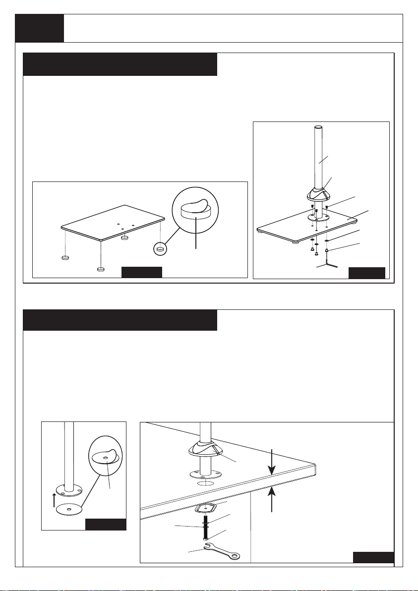
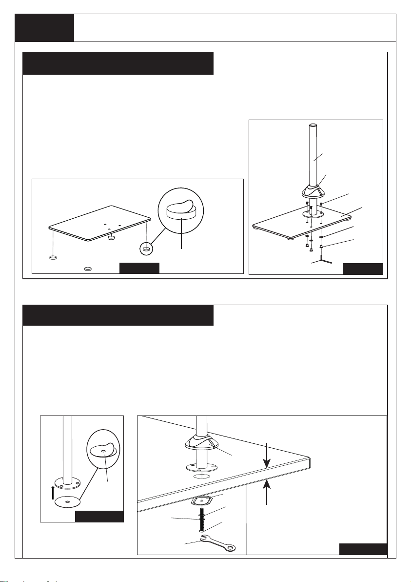
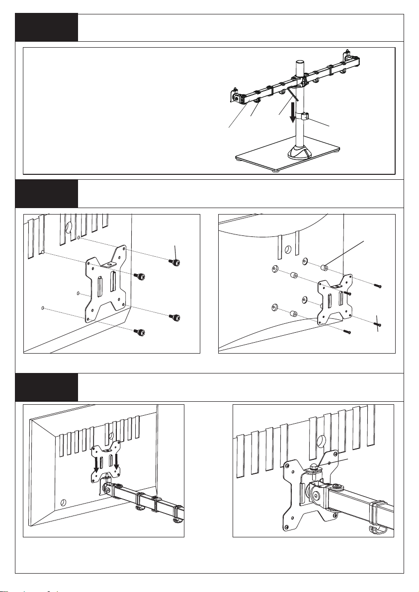
Schritt 1 Installieren Sie die Stange auf der Hartglas Basis
Auswahl A: Hartglas Basis Installation
Abbildung 4
Abbildung 3
Auswahl B: Tüllenbasis Installation
Vorhandene Tüllenbohrung
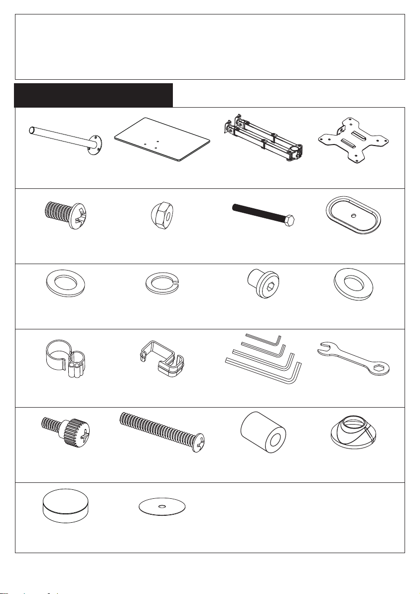
1. Weiche Unterlage (u) an der Stange (a) anbringen, siehe Abbildung 3.
2. Positionieren Sie die Stange (a) auf der Montagefläche und setzen Sie die Feder
Unterlegscheibe (j), die M10-Unterlegscheibe (i) und die Stützplatte (h) in die M10 Bolzen (g) ein.
Verwenden Sie den mitgelieferten Schraubenschlüssel (o), um die M10-Schraube an der Stange
zu befestigen. Setzen Sie die dekorative Abdeckung (en) an der Stange (a) ein. Siehe Abbildung 4.
Abbildung 1 Abbildung 2
b
k
n
l
e
s
a
1.Schraubenfüße (t) an der Hartglas Basis (b) anbringen, siehe Abbildung 1.
2.Installieren Sie die Stange (a) an der Hartglas Basis (b)
mit Bolzen M6x10 (e). Bolzen (k) und Unterlegscheibe (l) zu
der Stange von der Unterseite der Hartglas Basis verbinden.
Ziehen Sie den Bolzen (k) mit dem Inbusschlüssel (n) an.
Fügen Sie das ein
Dekorative Abdeckung (S) an der Stange (a). Siehe
Abbildung 2.
6
t
Tischplatte `Dicke:
0-80mm(0-3.15in.)
g
j
o
i
h
s
u

Arm zu der Stange installieren
VESA Platte zu dem Monitor verbinden
Installieren Sie den Schwenkarm (c) an der
Stange (a). Befestigen Sie die Schraube mit
dem mitgelieferten Inbusschlüssel (n).
Befestigen Sie die Kabel Klemme (m1, m2) an
der Stange (a) und am Schwenkarm (c).
Schritt 2
r
q
f
p
Schritt 3
Schieben Sie den Monitor auf den Kopf des Schwenkarms
Schritt 4
Für Monitor mit Flachbildschirm Für Monitor mit Curved Bildschirm
Schieben Sie den Monitor wie in der
Abbildung oben gezeigt auf den Kopf des
Schwenkarms (c).
Installieren Sie die Sicherheitsmutter (f).
Stellen Sie sicher, dass die Sicherheitsmutter
installiert ist, bevor Sie den Monitor drehen.
c
m2 n
m1
7

m1
Ziehen Sie die Schraube mit dem mitgelieferten
Inbusschlüssel (n) fest, um den Neigungswinkel
festzulegen.
Verwenden Sie den mitgelieferten Inbusschlüssel
(n), um die erforderlichen Einstellungen
vorzunehmen.
Verwalten Sie das Kabel und bewahren Sie die
Inbusschlüssel (n) zur späteren Verwendung in
einer Kabelklemme (m1) auf.
Wenn ein Monitor tiefer liegt, entfernen Sie die
Schraubenmutter (f) und drehen Sie den Bolzen
mit dem mitgelieferten Inbusschlüssel (n) gegen
den Uhrzeigersinn, um den Monitor anzuheben.
Installieren Sie die Schraubenmutter (f) nach
der Einstellung.
n
Nehmen Sie die notwendigen Einstellungen vor
Schritt 5
Verwalten Sie die Drähte und bewahren Sie die
Inbusschlüssel in der Kabel Klemme auf
Schritt 6
n
n
8

FR
Pièces et Matériel Inclus
Boulon M10
g (x1)
Clé Allen
n (x1)
Ecarteur M4
r (x8)
Boulon de connexion
k (x3)
Bras pivotant
c (x1 )
Plaque de support
h (x1)
Plqaue VESA
d (x2)
Clef
o (x1)
Couvercle décoratif
s (x1)
Rondelle M8
l (x3)
Ecrou
f (x2)
Clip de fil
m2 (x4)
Boulon M4 x 30
q (x8)
Bourrelet
u (x1)
Base pondérée
b (x1)
Rondelle élastique
j (x1)
Poteau
a (x1)
Boulon M6 x 10
e (x3)
Clip de fil
m1 (x1)
Goujon M4 x 12
p (x8)
Pied en caoutchouc
t (x4)
Rondelle M10
i (x1)
Le produit contient du verre. Ne utilisez pas le produit si vous
trouvez le verre cassé. Veuilez contacter notre service de
clientèle pour obtenir l’assistance.
9

Etape 1 Installer le poteau sur le bureau
Option A: Installation de la base pondérée
Figure 4
Option B: Installation de la base d’oeillet
Installation du trou à oeillet existant
Attachez le bourrelet (u) au poteau (a) selon Figure 3.
Positonnez le poteau (a) sur la surface de montage et insérez la rondelle élastique (j), la rondelle
M10 (i) et la plaque de support (h) dans le boulon M10 (g). Utilisez la clef (o) fournie pour fixer le
boulon M10 au poteau. Insérez le couvercle décoratif (s) dans le poteau selon Figure 4.
Figure 1 Figure 2
b
k
n
l
e
s
a
1.Attachez les pied en caoutchouc (t) à la base pondérée(b) selon Figure 1.
2.Installez le poteau (a) à la base pondérée à l’ aide de
boulons M6 x 10 (e). Reliez du bas de la base pondéreée le
boulon (k) et la rondelle (l) au poteau. Serrez le boulon (k) à
l’ aide de clé Allen (n). Insérez le couvercle décoratif (s)
dans le poteau (a) selon Figure 2.
10
t
épaisseur du plateau:
0-80mm(0-3.15in.)
Figure 4
g
j
o
i
h
s
Figure 3
u

Installer le bras au poteau
Attacher la plaque VESA au moniteur
Installre le bras pivotant (c) au poteau (a).
Serrez le boulon à l’ aide de clé Allen (n)
fournie. Attachez le clip de fil (m1, m2) au
poteau (a) et au bras pivotant (c).
Etape 2
r
q
f
p
Etape 3
Glisser le moniteur sur la tête du bras pivotant
Etape 4
Pour le moniteur à dos plat Pour le moniteur à dos incurvé ou encastré
Glissez le moniteur sur la tête du bras
pivotant (c) selon le diagramme indiqué
ci-dessus.
Installez l’ écrou de sécurité (f). Assurez-vous
que l’ écrou de sécurité est installé avant que
vous tourniez le moniteur.
c
m2 n
m1
11

m1
Serrez le boulon à l’ aide de clé Allen (n)
fournie pour fixer l’ angle d’ inclinaison.
Utilisez la clé Allen (n) pour faire des
ajustements nécessaires.
Maniez les fils et stockez les clés Allen (n) sur le
clip de fils (m1) pour les utiliser plus tard.
Si le moniteur est plus bas, retirez l’ écrou (f)
et tournez le compteur de boulons – tournez
dans le sens horaire à l’ aide de clé Allen (n)
pour élever le moniteur. Installez l’ écrou après
l’ ajustement.
n
Faire les ajustements nécessaires
Etape 5
Manier les fils et stocker les clés Allen sur le clip
de fils
Etape 6
n
n
12

Piezas y Equipo Incluidos
M10 Tornillo
g (x1)
Llave Allen
n (x1)
M4 Separador
r (x8)
Tornillo de Conexión
k (x3)
Brazo Giratorio
c (x1)
Placa de Soporte
h (x1)
Placa VESA
d (x2)
Llave
o (x1)
Cubierta Decorativa
s (x1)
M8 Arandela
l (x3)
Tuerca
f (x2)
Abrazadera de Alambre
m2 (x4)
M4x30 Tornillo
q (x8)
Almohadilla Suave
u (x1)
Base Fuerte
b (x1)
Arandela de Resorte
j (x1)
Palo
a (x1)
M6x10 Tornillo
e (x3)
Abrazadera de Alambre
m1 (x1)
M4x12 Tornillo de Mano
p (x8)
Pies de Goma
t (x4)
M10 Arandela
i (x1)
Este producto contiene vidrio. NO lo use si encuentra el vidrio
ROTO. Por favor póngase en contacto con nuestro servicio al
cliente para asistencia.
13

Paso 1 Instalar el Palo al Escritorio
Opción A: Instalación de la Base Fuerte
Opción B: Instalación de Base de Ojal
Instalación de Orificio de Ojal Existente
1. Fije la Almohadilla Suave (u) al Palo (a), véase Figura 3.
2. Coloque el Palo (a) en la superficie de montaje e inserte la Arandela de Resorte (j), M10
Arandela (i) y Placa de Soporte (h) al M10 Tornillo. Utilice la Llave (o) ofrecida para sujetar el
M10 Tornillo al Palo. Inserte la Cubierta Decorativa (s) al Palo (a). Véase Figura 4.
Figura 1 Figura 2
b
k
n
l
e
s
a
1. Fije los Pies de Goma (t) a la Base Fuerte (b), véase Figura 1.
2. Instale el Palo (a) a la Base Fuerte (b) utilizando M6x10
Tornillo (e). Conecte Tornillo (k) y Arandela (l) al palo del
fondo de la base fuerte. Apriete Tornillo (k) con Llave Allen
(n). Inserte la Cubierta Decorativa (s) al Palo (a). Véase
Figura 2.
14
t
grosor del escritorio:
0-80mm(0-3.15in.)
Figure 4
g
j
o
i
h
s
Figure 3
u

Instalar el Brazo al Palo
Asegurar la Placa VESA al Monitor
Instale el Brazo Giratorio (c) al Palo (a). Apriete
el tornillo con la Llave Allen (n) suministrada.
Asegure la Abrazadera de Alambre (m1, m2) al
Palo (a) y el Brazo Giratorio (c).
Paso 2
r
q
f
p
Paso 3
Deslizar el Monitor sobre la Cabeza del Brazo Giratorio
Paso 4
Para Monitor con Espalda Plana Para Monitor con Espalda Curva o Empotrada
Deslice el monitor sobre la cabeza del
Brazo Giratorio (c) como se muestra en el
diagrama de arriba
Instale la Tuerca de seguridad (f). Asegúrese
de que la tuerca de seguridad sea instalada
antes de que rote el monitor.
c
m2 n
m1
15

m1
Apriete el tornillo con la Llave Allen (n)
suministrada para fijar el ángulo de inclinación.
Utilice la Llave Allen (n) suministrada a hacer los
ajustes necesarios.
Maneje los cables y guarde las llaves Allen (n)
en la Abrazadera de Alambre (m1) para el uso
en futuro.
Si un monitor está más bajo, retire la Tuerca (f)
y gire el tornillo en el sentido contrario a las
agujas de reloj con la Llave Allen (n)
suministrada para levantar el monitor. Instale la
Tuerca (f) después del ajuste.
n
Hacer Ajustes Necesarios
Paso 5
Manejar los Cables y Guardar las Llaves Allen en la
Abrazadera de Alambre
Paso 6
n
n
16

Parti e Hardware Inclusi
M10 Bullone
g (x1)
Chiave a Brugola
n (x1)
M4 Separador
r (x8)
Bullone di Collegamento
k (x3)
Braccio Girevole
c (x1)
Piastra di Supporto
h (x1)
Piastra VESA
d (x2)
Chiave Inglese
o (x1)
Cubierta Decorativa
s (x1)
M8 Rondella
l (x3)
Dado
f (x2)
Fermaglio Filo
m2 (x4)
M4x30 Bullone
q (x8)
Pad Morbido
u (x1)
Base Ponderata
b (x1)
Rondella Elastica
j (x1)
Polo
a (x1)
M6x10 Bullone
e (x3)
Fermaglio Filo
m1 (x1)
M4x12 Bullone Pollice
p (x8)
Pies de Goma
t (x4)
M10 Rondella
i (x1)
Questo prodotto contiene vetro. NON usare il prodotto se si
trova il vetro da rompere. Si prega di contattare il nostro
servizio clienti per l'assistenza!
17

Passaggio 1 Installare l'asta sul desktop
Opzione A: Installazione di base ponderata
Opzione B: Installazione della base con occhiello
Installazione del foro passacavo esistente
1. Attaccare il cuscinetto morbido (u) al polo (a), vedere la figura 3.
2. Posizionare l'asta (a) sulla superficie di montaggio e inserire la rondella elastica (j), la rondella
M10 (i) e la piastra di supporto (h) sul bullone M10 (g). Utilizzare la chiave fornita (o) per fissare il
bullone M10 al polo. Inserire le coperture decorative sul polo (a). Vedere la Figura 4.
Figura 1 Figura 2
b
k
n
l
e
s
a
1. Attaccare i piedi di macerie (t) alla base ponderata (b), vedere la figura 1.
2. Installare il polo (a) nella base ponderata (b) usando il
bullone M6x10 (e). Collegare il bullone (k) e la rondella (l) al
polo dal fondo della base pesata. Stringere il bullone (k) con
la chiave a brugola (n). Inserire le coperture decorative sul
palo (a). Vedere la Figura 2.
18
t
spessore del desktop:
0-80mm(0-3.15in.)
Figure 4
g
j
o
i
h
s
Figure 3
u

Installare il braccio al polo
Attaccare la piastra VESA al monitor
Installare il braccio girevole (c) sull'asta (a).
Fissare il bullone con la chiave a brugola in
dotazione (n). Attaccare il Filo metallico (m1,
m2) al Polo (a) e al Braccio Girevole (c).
Passaggio 2
r
q
f
p
Passaggio 3
Far scorrere il monitor sulla testa del braccio girevole
Passaggio 4
Per monitor con retro piatto Per monitor con retro curvo o da incasso
Far scorrere il monitor sulla testa del
braccio orientabile (c) come mostrato nel
diagramma sopra.
Installare il dado di sicurezza (f). Assicurarsi
che il dado di sicurezza sia installato prima di
ruotare il monitor.
c
m2 n
m1
19
Table of contents
Languages:
Other HUANUO TV Mount manuals

HUANUO
HUANUO HNMUA1 User manual

HUANUO
HUANUO HNDSK1 User manual

HUANUO
HUANUO HNCM15 User manual

HUANUO
HUANUO HNTVMC02 User manual

HUANUO
HUANUO HNCM12 User manual

HUANUO
HUANUO HNCM17 User manual

HUANUO
HUANUO HATS3 User manual

HUANUO
HUANUO HNSS8 User manual

HUANUO
HUANUO HNCM19 User manual

HUANUO
HUANUO HASSK5 User manual