Huawei Y511-U030 Operating instructions

uyongSpecial note: for the template content, if not for the product, please
delete, so as to avoid misleading.
Chinese version of repair manuals, all use Times New Roman font,
English version repair manual font all use Arial fonts. Document of the
second chapter and the sixth chapter is the fixed content, without any
modification.
XXXX Repair Manual
V1.0
Artificial :
Date:
Review :
Date:
Approval.:
Date:
Transient suppression diode 2
华为技术有限公司
Huawei Technologies Co.,Ltd.
版权所有 侵权必究
All rights reserved

XXXX The basic version Repair ManualV1.0
internal public
2013-09-25
华为机密,未经许可不得扩散
第2页,共 79 页
Revision record
Date
Release version
Revision cause
Modify chapter
Revision
description
Author

XXXX The basic version Repair ManualV1.0
internal public
2013-09-25
Huawei confidential, not to spread without permission
第3页,共 79 页
Catalogue
CHAPTER 1 PRODUCT PROFILE ..................................................................................................................4
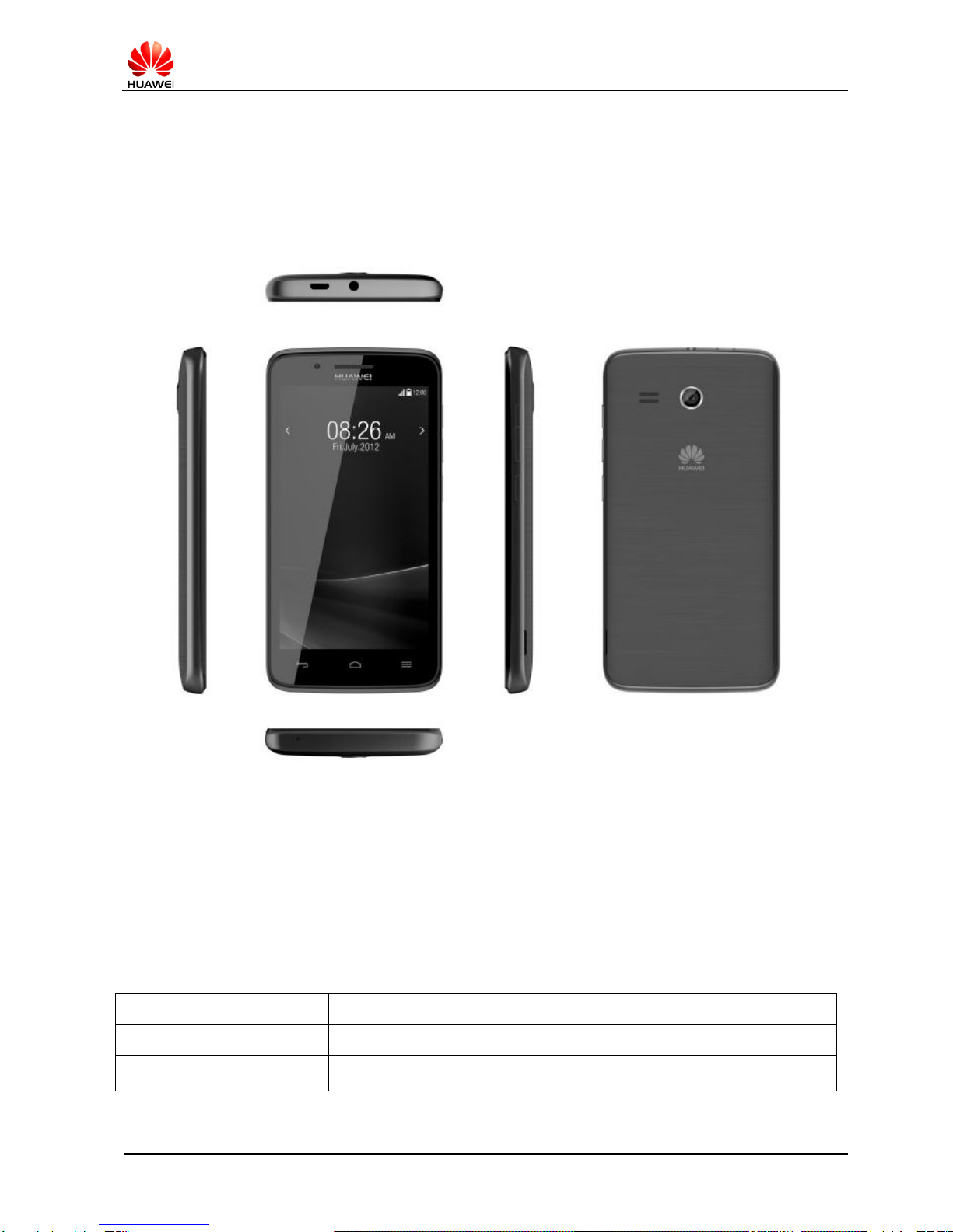
1.1 PRODUCT PICTURE ....................................................................................................................................4
1.2 CHARACTERISTICS OF THE PRODUCT........................................................................................................4
CHAPTER 2 REPAIR INSTRUCTIONS...........................................................................................................6
1.3 DOCUMENTATION........................................................................................................................................6
1.4 REPAIR THE MATTERS NEEDINGATTENTION...............................................................................................6
1.5 REPAIR INFORMATION ACQUISITION GUIDE LINES ......................................................................................6
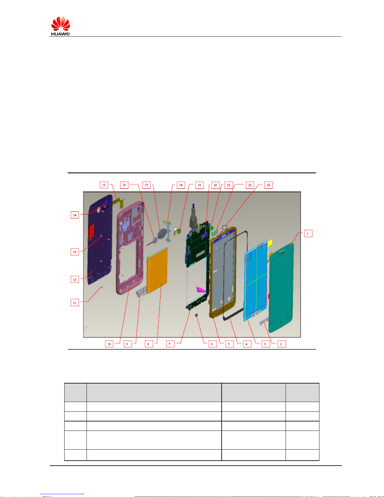
CHAPTER 3 PHONE EXPLOSION..................................................................................................................7
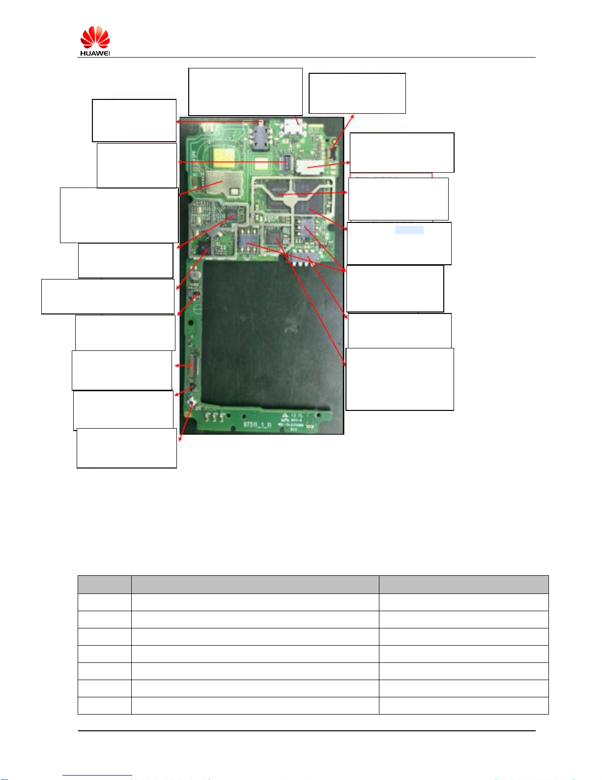
CHAPTER 4 PCBA COMPONENT LOCATION DIAGRAM.........................................................................9
CHAPTER 5 SW UPGRADE........................................................................................................................... 11
5.1 READY FOR UPGRADING ............................................................................................................................ 11
5.2 UPGRADE HARDWARE CONNECTION.......................................................................................................... 11
5.3 USB DRIVER INSTALLATION.......................................................................................................................12
5.4 UPGRADE PROCESS..................................................................................................................................15
5.4.1 USE“FLASH TOOL”TOOL ........................................................................................................................................15
5.4.2 CONFIGURE FLASHTOOL DOWNLOAD TOOL............................................................................................................15
5.5 SD UPGRADE .............................................................................................................................................20
5.6 EXCEPTION HANDLING...............................................................................................................................24
CHAPTER 6 SERVICE TOOL.........................................................................................................................25
CHAPTER 7 DISASSEMBLE STEP ..............................................................................................................27
CHAPTER 8 INSTALL STEP...........................................................................................................................30
CHAPTER 9 PRINCIPLE AND FAULT ANALYSIS .....................................................................................34
9.1 PRINCIPLE DIAGRAM AND INTRODUCTION.................................................................................................34
9.2 BASEBAND.................................................................................................................................................. 36
9.2.1 POWER MANAGEMENT CIRCUIT ............................................................................................................................36
9.2.2 CHARGING MANAGEMENT CIRCUIT .......................................................................................................................42
9.2.3 CLOCK CIRCUIT .......................................................................................................................................................44
9.2.4 FLASH CIRCUIT .......................................................................................................................................................46
9.3 RF UNIT ......................................................................................................................................................48
9.3.1 RECEPTION CHANNEL .................................................................................................................................................54
9.3.2 TRANSMITTING CHANNEL .............................................................................................................................................57
9.4 EXTERNAL CIRCUIT ........................................................................................................................................60
9.4.1 DISPLAY .................................................................................................................................................................60
9.4.2 KEYPAD .................................................................................................................................................................63
9.4.3 VIBRATION ..............................................................................................................................................................64
9.4.4 RECEIVER................................................................................................................................................................65
9.4.5 MIC .......................................................................................................................................................................67
9.4.6 EARPHONE................................................................................................................................................................69
9.4.7 SIM CARD ..............................................................................................................................................................70
9.4.8 INTERFACE ..............................................................................................................................................................73
9.4.9 SD CARD INTERFACE ................................................................................................................................................74
9.4.10 CAM ....................................................................................................................................................................75
9.4.11 BT/WIFI/FM/GPS FAILURE .................................................................................................................................78
9.4.12 OTHER COMMON FAILURE .....................................................................................................................................79

XXXX The basic version Repair ManualV1.0
internal public
2013-09-25
Huawei confidential, not to spread without permission
第4页,共 79 页
Chapter 1 Product Profile
1.1 Product Picture
1.2 Characteristics of the Product.
Description: the product characteristics shall include information, the most
basic hardware characteristics such as: mobile phone appearance, size,
weight, type, frequency band, interface, the display parameters, cell
parameters.
Item
description.
Phone Size
132.8*67.4*10.5
Phone weight;
About 160g (Including battery)

XXXX The basic version Repair ManualV1.0
internal public
2013-09-25
Huawei confidential, not to spread without permission
第5页,共 79 页
Antenna
Built-in antenna
SIM interface
Standard 6 PIN SIM interface
USB interface
Mini USB interface, Maintenance and supply for Telephones
Power interface
Mini USB interface
Power adapter
AC input:100V ~ 240V DC output :5v---1A
LCM
4.5 inch、FWVGA、TN、1600 Million color、380cd/m2(typ)
Working Environment;
Working temperature:-10℃~+55℃
Storage temperature:-40℃~+70℃
Operating humidity:5%~95%RH
Technical Standard;
Standard mobile phone technology of WCDMA digital
Work Frequency Band
UMTS:900/2100
GSM/EDGE:900/1800
GSM 900MHz:upgoing;880MHz~915 MHz;down 925MHz~960MHz
GSM 1800MHz:upgoing;1710MHz~1785MHz;down 1805MHz~
1880MHz
Maximum Transmit Power
GSM900:890-915MHz;GSM1800:1710-1785MHz WCDMA: 1940
–1955 MHz
Receiving Sensitivity
GSM900:935-960MHz;GSM1800:1805-1880MHz;WCDMA: 2130 –
2145 MHz

XXXX The basic version Repair ManualV1.0
internal public
2013-09-25
Huawei confidential, not to spread without permission
第6页,共 79 页
Chapter 2 Repair Instructions
1.3 Documentation
This document is used to guide the Huawei Company authorized outlets repair technicians to repair
service for Huawei Company products. This service manual only provides the Huawei Company has
authorized repair service outlets and the company use, and the contents of the confidential information.
Although we as far as possible to ensure the accuracy of this document, but may still be a mistake. If you
find any mistake or have more suggestions, please contact customer service staff and huawei.
Welding should meet the requirements of environmental protection, lead-free welding.
1.4 Repair the matters needing attention
Repair and adjustment only by qualified personnel operation.
Ensure all work is to wear anti-static belt and operation in anti-static studio.
Ensure that all components, screws and an insulator in the repair and adjustment are installed.
And to ensure that all cables and wires have been installed in place.
Welding should meet the requirements of environmental protection, lead-free welding.
1.5 Repair information acquisition guide lines
Relevant knowledge of products and repair information, please log in Huawei Company Website
Website:http://www.huaweidevice.com/cn/technicaIndex.do
Electrostatic discharge is the main reason for electronic products sensitive components
damaged, so each service center must attach great importance to the electrostatic protection,
also want to pay attention to the electrostatic protection of this manual.

XXXX The basic version Repair ManualV1.0
internal public
2013-09-25
Huawei confidential, not to spread without permission
第7页,共 79 页
Chapter 3 Phone Explosion
Explain:
1. The explosion picture requires the use of 3D pictures, pictures of clear
structure, device on the picture to digital serial number label, and the
sequence number corresponding to that device list name, quantity.
2. Images need to use "the drawing canvas" frame up.
Explosion lists:
Describe the whole structure description graph is BOM explosion in the table below, can not be used as
a reference for spare parts:
No.
description
Huawei material
number
Single
dose
1
S98511A1 CTP
1
2
S98511A1 Light guide film
1
3
S98511A1 LCM
1
4
S98511A1 CTP Foam tape
1
5
S98511A1 front cover assembly
1

XXXX The basic version Repair ManualV1.0
internal public
2013-09-25
Huawei confidential, not to spread without permission
第8页,共 79 页
No.
description
Huawei material
number
Single
dose
6
S98511A1 MIC
1
7
S98511A1 PCBA
1
8
S98511A1 Battery
1
9
S98511A1 Main antenna bracket assembly
1
10
S98511A1 Back cover assembly
1
11
Black bolt
4
12
S98511A1 Battery cover assembly
1
13
Silver screw
5
14
S98511A1 Camera lens
1
15
S98511A1 GPS/WIFI antenna
1
16
S98511A1 1020 Motor
1
17
S98511A1 2014 Speaker
1
18
S98511A1 side key FPC assembly
1
19
S98511A1 back CAM
1
20
S98511A1 front CAM
1
21
S98511A1 Proximity sensor
1
22
1506 receiver
1
23
Waterproof label
1

XXXX The basic version Repair ManualV1.0
internal public
2013-09-25
Huawei confidential, not to spread without permission
第9页,共 79 页
Chapter 4 PCBA Component Location
Diagram
Explain
:
1. All PCBA host will need to provide a positive and negative picture, need to
mark the main device on a PCBA board, tagging content includes: No., device
name, damage caused by fault phenomenon.
2. Image requirements to clear: for the device image annotation, users can
find the real position corresponding to the need to use "; the picture frame
drawing canvas".
3.The picture on the label and instructions corresponding to the characters
must be editable.

XXXX The basic version Repair ManualV1.0
internal public
2013-09-25
Huawei confidential, not to spread without permission
第10 页,共 79 页
This list is for reference only, subject to change without notice, please obtain the latest information from
the relevant system Huawei company. If you have any questions, please contact the local technical
support.
BOM
描述
位号
15040238
Transient suppression diode 2
D1401,D700
J902 6PIN ZIF connector
Damage caused by fault:
TP function failure
CON2 T card seat connector
Damage caused by fault:: not
read T card
U101 BBIC
Damage caused by fault:
No boot, crash, RF breakdown
U402 FLASH memory
Damage caused by fault:
No boot, no download, SW
question
J1101, J1102 SIM card seat
Damage caused by fault:
Not read SIM card
CON301 battery interface
Damage caused by fault:
No boot, no charging
U301 power management chip
Damage caused by fault:
No boot, audio fault, not read SIM
card , not read T card, no
download. etc
U600 RF transceiver chip
caused by fault: RF fault
U1000 BT/WIFI/GPS/ FM Chip
caused by fault::
BT/WIFI/GPS/FM function fault
J0003 BTB interface
caused by fault:: rear
CAM function fault
J501 ear interface
Damage
caused by fault:: ear
function fault
CON 701 IO interface Micro
Damage caused by fault::: no
charging ,Data communication
fault
U1 RF power amplifier
Damage caused by fault: launch failure
U901 backlight chip
Damage caused by fault:
Screen backlight off
J6401 ZIF interface
Damage caused by fault:
Lcd function fault
J6401 Motion Chip
Damage caused by fault:
No effect of gravity
J700 RF test seat
Damage caused by fault:
No signal, weak signal, no
registration

XXXX The basic version Repair ManualV1.0
internal public
2013-09-25
Huawei confidential, not to spread without permission
第11 页,共 79 页
Chapter 5 SW Upgrade
Explain
:
1.The need for a detailed description of the upgrade, the upgrade tool
environment, matters needing attention, the upgrade process needs
specific to each step how to operate.
2.Each upgrade needs to write detailed upgrade instructions.
3.Requires a clear picture, need to use "the drawing canvas" frame up.
4.The picture on the label and instructions corresponding to the
characters must be editable.
5.1 Ready for upgrading
ITEM
CONTENT
Remark
Upgrade
environment
Computer
Operating system:Windows 2000、Windows XP
USB Date cable
BOM: 02450768
Upgrade tool
FPQPML01
Micro SD
>512M
Battery
Battery must be greater than 20%
Upgrade file
XXXX
This is the reference version, please download the
latest version of the upgrade
Upgrade Method
“FPQPML01”
Normal upgrade
Force to upgrade
SD card
Normal upgrade
Force to upgrade
5.2 Upgrade hardware connection
Y511 Product
USB Cable
便携机 1
PC
PC

XXXX The basic version Repair ManualV1.0
internal public
2013-09-25
Huawei confidential, not to spread without permission
第12 页,共 79 页
5.3 USB Driver installation
Install the driver, please enter the main menu - > Settings > developers the option "USB
debugging" (if not the developer settings option, please click "mobile phone menu, click on
the" fast "version number" column of about 5 times, which will prompt in developer mode,
then back to the set interface will see "developers options" menu), and then use the
upgraded lines connected mobile phone and PC terminal, PC terminal will pop up later
driver installation tips, operation process diagram as follows:
"No, no (T)" option, click Next to install it. The following chart

XXXX The basic version Repair ManualV1.0
internal public
2013-09-25
Huawei confidential, not to spread without permission
第13 页,共 79 页
Select "install from a list or specify the location (Senior) (S)" option, click Next to
continue installation.
Select "search for the best driver" option in these locations, select "include this location in
the search", click "Browse" button to select the driver file SP_Drivers_v1.5, click next to
continue installation.

XXXX The basic version Repair ManualV1.0
internal public
2013-09-25
Huawei confidential, not to spread without permission
第14 页,共 79 页
Wait a moment, the installation is complete, the following diagram:
Click "finish" button, to complete the installation.
After the installation is completed in the computer device manager will appear in the
corresponding COM port, as shown below:

XXXX The basic version Repair ManualV1.0
internal public
2013-09-25
Huawei confidential, not to spread without permission
第15 页,共 79 页
5.4 Upgrade Process
5.4.1 Use“flash tool” tool
1. This download tools do not need to install, double-click the folder "Flash_tool.exe"
operation to open the tool software, after the operation of the interface is as follows:
5.4.2 Configure flashtool download tool
1) Under the Options USB Mode download mode, the configuration of Speed in DA Download All to
High Speed Force. The following diagram

XXXX The basic version Repair ManualV1.0
internal public
2013-09-25
Huawei confidential, not to spread without permission
第16 页,共 79 页
Choose USB Mode
Configure Speed is Force to High Speed
2) Download Agent options, click on the interface, select the Flash_tool folder in the
MTK_AllInOne_DA.bin file. The following diagram:
3) Click the Scatter-loading button (figure a red box shown in the corresponding button), path selection,
you need to download the software package of scatter file file (the words scatter.Txt file), open (as
shown in Fig. two):
Fig 1

XXXX The basic version Repair ManualV1.0
internal public
2013-09-25
Huawei confidential, not to spread without permission
第17 页,共 79 页
Fig 2
To download the package related documents of all after the OK implementation, the
interface is shown below:
5.4.3 Software upgrade of USB (for Y511)
1) Click the Firmware->Upgrade button to start the download, display interface:

XXXX The basic version Repair ManualV1.0
internal public
2013-09-25
Huawei confidential, not to spread without permission
第18 页,共 79 页
click on the Download button will also be available for download, but if all the upgrades
to select the Firmware->Upgrade button.
2) The USB cable to connect the PC machine, mobile phone battery is out (or not to
unplug the battery, but to ensure that the mobile phone is switched off), USB cable to
connect the mobile phone terminal, to download, the download process as shown in
Figure one -- two --three -- > four sequence is shown:
Fig 1
Fig 2
Fig 3
Fig 4
3) Upgrade is complete, when the download progress display interface 100%, Green
box OK means the upgrade was completed successfully. The following chart::

XXXX The basic version Repair ManualV1.0
internal public
2013-09-25
Huawei confidential, not to spread without permission
第19 页,共 79 页
End: close Firmware Upgrade OK suggests that small window, mobile phone terminal
removal of the USB line, shut down the window, the mobile phone to boot into the
engineering model verification software version.
Attentions:
Download the software: first, to ensure that the mobile phone is not connected PC machine; open the
Flash_tool.exe download tool, select download, configuration for high-speed download, then select the
loading file scatter file; click the Firmware Upgrade button; select OK, then connect the mobile phone;
mobile phone connection, first remove the battery or the mobile phone shutdown, then connect the PC
download.
The Firmware Upgrade button and Download button is to start the download button, but because the
more import to download the file, if due to misoperation or other circumstances lead to import download
files not all checked, click on the Download button is not prompt file missing and direct download, but
click on the Firmware Upgrade button if the file is not all check will prompt and can not download,
therefore directly using the Firmware Upgrade button, avoid downloading when selected file cause some
be rather baffling problem.

XXXX The basic version Repair ManualV1.0
internal public
2013-09-25
Huawei confidential, not to spread without permission
第20 页,共 79 页
5.5 SD upgrade
Y511 supports two SD card SD card upgrade, the circumstance SD card upgrade and
shutdown conditions two upgrade
SD card upgrade for mobile phone operation mode
1. The SD card root directory create folder dload, the SD card upgrade package name
changed to update.zip, placed in the dload folder, namely the SD card upgrade path for
"SD card root directory \dload\update.zip"
2. Boot entrance case SD card upgrade are the settings - > memory > software update
- > memory card to upgrade - > (warning interface) to determine the - > OK, started off
into the automatic upgrade, boot automatically after the completion of upgrading. The
whole process as shown below
Table of contents
Other Huawei Cell Phone manuals

Huawei
Huawei ATU-LX3 User manual

Huawei
Huawei G6-U10 User manual

Huawei
Huawei Y6 User manual

Huawei
Huawei KIW-A1 User manual

Huawei
Huawei U1000-5 User manual

Huawei
Huawei U8520-1 User manual

Huawei
Huawei P8 lite Installation guide

Huawei
Huawei U8655 User manual

Huawei
Huawei P9 Plus User manual

Huawei
Huawei U2800A User manual

Huawei
Huawei U8500 User manual

Huawei
Huawei STK-L22 User manual

Huawei
Huawei G7010 User manual

Huawei
Huawei FIG-LX1 User manual

Huawei
Huawei Red Bull RBM HD User manual

Huawei
Huawei U1250 User manual

Huawei
Huawei U1270-7 User manual

Huawei
Huawei Magna H871G User manual

Huawei
Huawei P9 LITE User manual

Huawei
Huawei P8 GRA-UL00 Dimensions