manuals.online logo
Brands
  1. Home
  2. •
  3. Brands
  4. •
  5. Huawei
  6. •
  7. Power Supply
  8. •
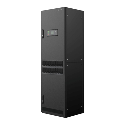
  9. Huawei UPS5000-H-400K-FT User manual

Huawei UPS5000-H-400K-FT User manual

Surge protection
boxes (optional)
Output switch
UPS5000-H-(400 kVA-600 kVA)-FT Quick Guide (100 kVA Power Modules)
01 Installation Preparations
Model Weight Dimensions (H x W x D)
UPS5000-H-400K-FT < 750 kg
2000 mm x 800 mm x 1000 mmUPS5000-H-500K-FT < 805 kg
UPS5000-H-600K-FT < 860 kg
Unpacking
Securing the Cabinet
A: mounting holes
on the channel steel
B: mounting holes
on the floor
unit: mm
Issue: 04
Date: 2022-12-29
Item 400 kVA 500 kVA 600 kVA Remarks
Mains input
Mains input current (A)
743
929
1115
Connection method:
Crimped DT terminal
Bolt Specifications:
L1/L2/L3/U/V/W/+/
-:
M16 x 55 mm
(120 N·m)
PE: M12 x 30 mm
(47 N·m
)
Equipotential ground point:
M6 x 20 mm
(4.5 N·m)
NOTE:
The currents listed in the
table are measured at a
rated voltage of 380 V.
Recommended cross
-
sectional area (mm
2)
L1/L2/L3/N
2 x (4 x 240)
3 x (4 x 185)
4 x (4 x 185)
PE
240
Bypass input
Bypass input current (A)
608
760
912
Recommended cross
-
sectional area (mm
2)
L1/L2/L3/N
2 x (4 x 240)
3 x (4 x 185)
4 x (4 x 185)
PE
240
Output
Output current (A)
608
760
912
Recommended cross
-
sectional area (mm
2)
U/V/W/N
2 x (4 x 240)
3 x (4 x 185)
4 x (4 x 185)
PE
240
Battery input
(lead
-acid
battery)
Nominal battery discharge current (A)
877
1108
1330
Maximum battery discharge current (A)
1062
1327
1593
Recommended cross
-
sectional area (mm
2)
+/
-
2 x
(2 x
240)
3 x
(2 x 185)
3 x
(2 x 240
)
PE
240
Battery input
(SmartLi
)
Nominal battery discharge current (A)
831
1039
1247
Maximum battery discharge current (A)
1043
1304
1564
Recommended cross
-sectional area
(mm
2)
For details, see the IEC
-60364-5-52
specifications and
SmartLi User Manual.
Equipotential
ground point
Recommended cross
-sectional area
(mm
2)
16
1. Before installation, read the user manual carefully to get familiar with product information and safety precautions.
2. Use insulated tools when installing the equipment.
3. Only qualified professionals or trained personnel are allowed to install, commission, and maintain the UPS.
Otherwise, personal injury or equipment damage may occur, and the caused UPS damage is not covered under any
warranty or service agreement.
4. This document describes the operation procedure for a single UPS. For details about how to operate a parallel
system, see the user manual.
1
Space Planning
02 Installing Cabinets
Recommended Power Cables
Cabinet Description
Power modules
Bypass input switch
Bypass module
Mains input switch
Monitor display unit
Switch handle
Control module
Intelligent
detection card
Maintenance
bypass switch
UPS5000-H-600K
Surge protection
boxes (optional)
Output switch
Power modules
Bypass input switch
Bypass module
Mains input switch
Monitor display unit
Switch handle
Control module
Intelligent
detection card
Maintenance
bypass switch
UPS5000-H-400K
Five power modules are
configured for the 500
kVA model, and six power
modules for the 600 kVA
model. The figure uses
the 600 kVA model as an
example.
Copyright © Huawei Digital Power Technologies Co., Ltd. 2022. All rights reserved.
全局信息
2
04 Verifying the Installation
03 Installing Cables
UPS5000-H-(400 kVA-600 kVA)-FT Quick Guide (100 kVA Power Modules)
1. Remove the top cover. (There is no need to
reinstall it.)
3. Install ground cables. 4. Install power cables.
6. Install the top beams. (delivered with the product) 7. Connect signal cables.
Battery input
2. Remove the epoxy separators.
5. Reinstall the epoxy separators.
Do not remove the
dustproof cover before
power-on.
Paper protective
film
Sealing putty
Transparent film
1. Check that there is no foreign matter in the cabinets.
2. After routing cables and verifying cable connections,
seal the gap between cables and the cabinet using
sealing putty. (Remove the paper protective film from
the sealing putty and retain the transparent film.
When using the putty, ensure that the transparent
film faces upward.)
3. After verifying the installation, reinstall all the covers.
4. Do not remove the dustproof cover before power-on
to prevent dust from entering the UPS.
Different Power Sources
Single Power Source
AC input UPS output
Battery input
Mains
input UPS output
Bypass
input
Monitoring
Interface Card
Ambient
T/H Sensor
Dry Contact
Card
NC connection
NO connection
SmartLi (Master)
Equipotential
ground
PE
When installing AC input power cables,
if there are a great number of cables
and the wiring holes in the mains input
copper bar are insufficient, connect the
cables to the corresponding holes in
the bypass input copper bar.
05 Power-On Commissioning
Powering On the UPS
5.1
Turn on the UPS bypass input switch, mains input switch, and output switch.
After the UPS is powered on, initialization begins. The monitoring display unit (MDU)
displays the initialization progress bar.
1. Before powering on the UPS5000, ensure that the check items in the
UPS5000 Startup
Service Report
and the post-installation check items are verified.
2. Measure the voltage and frequency of the UPS upstream input switch. The line voltage
range is 138–485 V AC, and the frequency range is 40–70 Hz.
Initial Startup
5.2
2. Set the language, time, date, network parameters, and system parameters on the Settings
Wizard screen.
Starting the Inverter
5.3
3. After you perform the settings, the Bypass mode and No battery alarms are reported by the
MDU and do not need to be cleared. If there is any other alarm, you need to rectify the fault.
4. If the system has connected to the remote EPO switch, you need to choose Monitoring > UPS
System > Running Parameter > System Settings on the WebUI and set EPO detection to
Enable.
5. View the system running status diagram on the MDU to check that the UPS is working in
bypass mode.
Powering On Loads
5.4
06 Shutting Down the UPS
Set all battery parameters according to the actual situation: Assume that the battery
specifications are 150 Ah/12 V, 40 batteries are connected in series, and two battery strings
are connected to the UPS in parallel. Set Single battery voltage(V) to 12, Single battery
capacity(Ah) to 150, Battery in a battery string to 40, and Number of battery strings to 2.
System User LCD Preset
Password
WebUI Preset
Password
admin (system administrator)
000001 Changeme
operator (common user) 000001 Changeme
1. On the main menu, choose Common Functions and tap Inv. ON.
2. In the displayed login window, enter the user name and password, and tap .
3. In the displayed dialog box, tap Yes to start the inverter.
To ensure system security,
change the LCD and
WebUI passwords after
the first login.
1. After the inverter starts, the UPS works in normal mode. The Bypass mode alarm disappears
from the MDU.
2. After confirming that the battery strings are properly connected, turn on the battery string
input circuit breaker. If there are multiple battery strings, turn on the circuit breaker for each
battery string and then turn on the general circuit breaker between battery strings and the
UPS. The No battery alarm disappears from the MDU.
3. Turn on the UPS downstream output switch to supply power to the loads.
After you shut down the inverter, the UPS transfers to bypass mode if the bypass is normal;
the UPS supplies no power if the bypass is abnormal. Before shutting down the UPS, ensure
that all loads have been shut down.
Powering Off a Single UPS
6.2
Shutting Down the Inverter to Transfer the UPS to Bypass Mode
6.1
(Optional) Setting Parameters for the BCB Box
5.5
1. On the main menu of the LCD, choose Common Functions and tap Inv. OFF.
2. In the displayed login window, enter the user name and password, and tap .
3. In the displayed dialog box, tap Yes to shut down the inverter.
If a BCB box is configured, set MUE05A connection to Enable in System Info > Settings > Dry
Contacts Set, and then set BCB connection [OL] and Battery breaker [STA] to Enable.
Turn off the downstream output switch.
Turn off the UPS mains input switch, bypass input switch, and output switch.
Turn off the battery string circuit breaker. If there are multiple battery strings, turn
off the general circuit breaker between battery strings and the UPS and then
turn off the circuit breaker for each battery string.
Turn off the upstream mains and bypass input switches.
3
UPS5000-H-(400 kVA-600 kVA)-FT Quick Guide (100 kVA Power Modules)
Turn on the upstream bypass and mains input switches.
•To turn on a switch, insert the switch handle in place, and then rotate
the handle.
•After turning on the switch, ensure that the triangle arrow on the
flange points to ON.
Switch handle placed on the tray of the front
door. Four switches share one handle. Remove
the handle before operating different switches
and reinstall it after the operations are complete.
•To turn off a switch, insert the switch handle in place, and then rotate the
handle.
•After turning off the switch, ensure that the triangle arrow on the flange
points to OFF.
Huawei Digital Power Technologies Co., Ltd.
Huawei Digital Power Antuoshan Headquarters
Futian, Shenzhen 518043
People’s Republic of China
www.huawei.com
1. Obtain the startup password through the app. After the application is approved, enter the
password on the service authorization screen of the device to complete device authorization.
Technical support engineers can obtain the service authorization code through the app. For
details, see the
Data Center Facility Deployment Guide
.
If desiccant is available inside the cabinets, remove the desiccant.
Other manuals for UPS5000-H-400K-FT

1

This manual suits for next models

2

Other Huawei Power Supply manuals

Huawei ETP48400-C9A2 User manual

Huawei

Huawei ETP48400-C9A2 User manual

Huawei FusionPower6000 User manual

Huawei

Huawei FusionPower6000 User manual

Huawei ETP4830-A1 User manual

Huawei

Huawei ETP4830-A1 User manual

Huawei UPS5000-H-800K-NTN User manual

Huawei

Huawei UPS5000-H-800K-NTN User manual

Huawei TP48200A-HT15D3 User manual

Huawei

Huawei TP48200A-HT15D3 User manual

Huawei UPS2000 Series User manual

Huawei

Huawei UPS2000 Series User manual

Huawei TP48200A-HX09A2 User manual

Huawei

Huawei TP48200A-HX09A2 User manual

Huawei TP48200A-DX08A1 User manual

Huawei

Huawei TP48200A-DX08A1 User manual

Huawei UPS5000-S Series User manual

Huawei

Huawei UPS5000-S Series User manual

Huawei TP48200A-HX09A2 User manual

Huawei

Huawei TP48200A-HX09A2 User manual

Huawei TP48200A-HT15D3 User manual

Huawei

Huawei TP48200A-HT15D3 User manual

Huawei UPS2000 Series User manual

Huawei

Huawei UPS2000 Series User manual

Huawei TP48200E-H12C1 User manual

Huawei

Huawei TP48200E-H12C1 User manual

Huawei TP48200A-D17A5-2 Telecom Power User manual

Huawei

Huawei TP48200A-D17A5-2 Telecom Power User manual

Huawei UPS2000-H-6 kVA User manual

Huawei

Huawei UPS2000-H-6 kVA User manual

Huawei SmartLi 3.0 User manual

Huawei

Huawei SmartLi 3.0 User manual

Huawei UPS5000-H-400 kVA User manual

Huawei

Huawei UPS5000-H-400 kVA User manual

Huawei UPS5000-S Series User manual

Huawei

Huawei UPS5000-S Series User manual

Huawei Telecom Power TP48200A-DT19C1 User manual

Huawei

Huawei Telecom Power TP48200A-DT19C1 User manual

Huawei UPS5000-E-12 User manual

Huawei

Huawei UPS5000-E-12 User manual

Huawei DPU40D-N06A3 User manual

Huawei

Huawei DPU40D-N06A3 User manual

Huawei V100R001C50 Instruction sheet

Huawei

Huawei V100R001C50 Instruction sheet

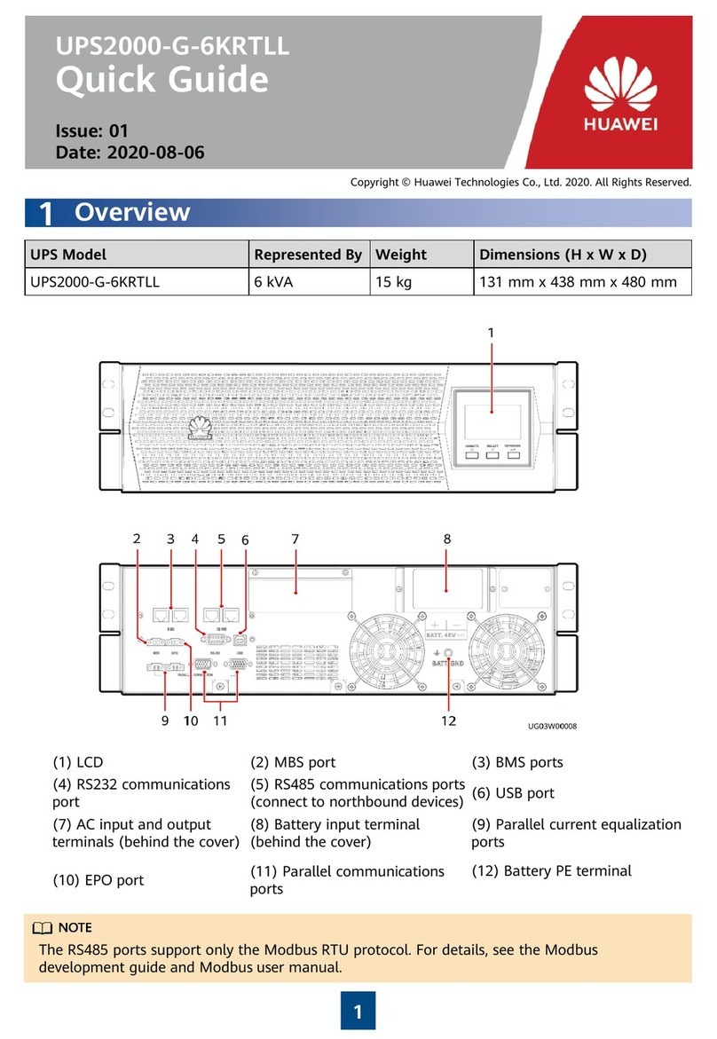
Huawei UPS2000-G-6KRTLL User manual

Huawei

Huawei UPS2000-G-6KRTLL User manual

Huawei Telecom Power TP48200A-HT19C3 User manual

Huawei

Huawei Telecom Power TP48200A-HT19C3 User manual

Popular Power Supply manuals by other brands

Scientific PSD3203 user manual

Scientific

Scientific PSD3203 user manual

Allied Telesis AT-PWR9 installation guide

Allied Telesis

Allied Telesis AT-PWR9 installation guide

Bosch MIC Series installation manual

Bosch

Bosch MIC Series installation manual

MW HDR-150 Series installation manual

MW

MW HDR-150 Series installation manual

Spectra M2-ATX-HV installation guide

Spectra

Spectra M2-ATX-HV installation guide

Altronix ALTV2416350 installation guide

Altronix

Altronix ALTV2416350 installation guide

Bluetti AC200L user manual

Bluetti

Bluetti AC200L user manual

Interlogix SuperBus 2000 installation instructions

Interlogix

Interlogix SuperBus 2000 installation instructions

Goobay 53999 user manual

Goobay

Goobay 53999 user manual

Hama 00039729 Operating	 instruction

Hama

Hama 00039729 Operating instruction

PS Audio UPC-200 Owner's reference

PS Audio

PS Audio UPC-200 Owner's reference

Puls CP10.241-R2 installation manual

Puls

Puls CP10.241-R2 installation manual

König Electronic CMP-PSUP350RW manual

König Electronic

König Electronic CMP-PSUP350RW manual

Elektro-Automatik PSI 9000 15U Series operating guide

Elektro-Automatik

Elektro-Automatik PSI 9000 15U Series operating guide

ELC DR07 manual

ELC

ELC DR07 manual

Ametek Sorensen XFR 7.5-300 manual

Ametek

Ametek Sorensen XFR 7.5-300 manual

Voodoo Lab PEDAL POWER ISO-5 user manual

Voodoo Lab

Voodoo Lab PEDAL POWER ISO-5 user manual

multicomp pro MP710079 user manual

multicomp pro

multicomp pro MP710079 user manual

manuals.online logo
manuals.online logoBrands
  • About & Mission
  • Contact us
  • Privacy Policy
  • Terms and Conditions

Copyright 2025 Manuals.Online. All Rights Reserved.