Huayu HYH-7.6K-NA/Pro User manual

For our home energy independence.
Huayu(Ningbo)New Energy Technologies Co., Ltd.
USER MANUAL
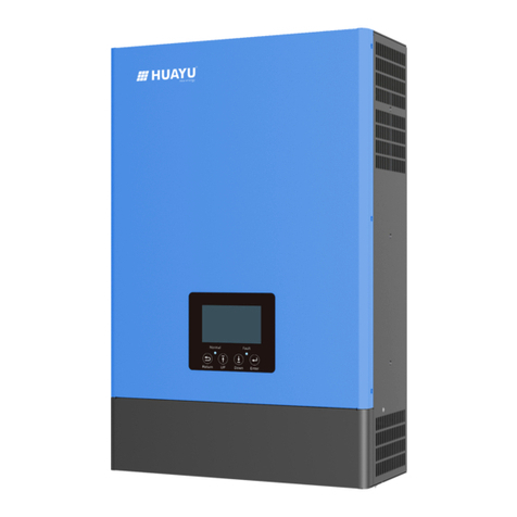
Huayu Hybrid Inverter
HYH-7.6K-NA/Pro
HYH-8K-NA/Pro
HYH-9K-NA/Pro
HYH-10K-NA/Pro
HYH-12K-NA/Pro

6.
Troubleshooting & Maintenance 30
7.
Fan Replace 34
30
30
31
6.1.1 Introduction to LED Displays
6.1.2 Maintenance
6.1.3 Troubleshooting Based on LCD Displays
30
6.1 Troubleshooting
Safety
1.
01
01
Contents
1.1 Safety Instruction
2.
3.
Brief Introduction
Installation 04
4.
Operation Guide 21
04
04
06
03
3.1 Packaging List & Storing
214.1 Operation Mode
214.2 LCD Settings
27
4.3 Huayu Portal Monitoring Platform
274.4 Parallel System Setup Guidance
3.2 Select Location
3.3 Install the Inverter
07
3.4 Connection
07
08
09
3.4.1 Connection Overview
3.4.2 PV Connection
3.4.3 Battery Connection
21
23
4.2.1 Information Searching
4.2.2 Settings Guidance
10
3.4.4 Communication Connection
12
14
3.4.5 US Model Grid/UPS Connection
3.4.6 Work with Gen Set
15
3.4.7 European Model Wiring Diagram
19
3.4.8 Meter and CT Connection 17
3.4.8.1 Connect the Meter
032.1 System Solution
18
3.4.8.2 Connect the CT
14
3.4.5.1 240V Single-phase Connection 13
3.4.5.2 240V/208V Split Phase Connection
19
3.4.8.3 DRMs Connection
20
3.4.8.4 Balancing Resistor Configuration - SW1
20
3.4.8.5 Wireless Communication Module Connection
Start-up and Shut Down the Inverter
5.
30
30
30
5.1 Start-up the Inverter
5.2 Shut Down the Inverter

Huayu(Ningbo)New Energy Technologies Co.,Ltd. All rights reserved.
c
01
1. Safety
1.1 Safety Instruction
General Safety Instructions
Important Safety Notifications
The inverter has been designed and tested strictly according to international safety regulations. Read all
safety instructions carefully prior to any work and observe them at all times when working on or with the
inverter. The operator must be qualified personnel and the installation must be capable with relevant
national or international standards or regulations.
Dangers of High Voltages and Large Current
Beware of high PV voltage. Please turn-off the DC switch of PV Panel output before and during
the installation to avoid electric shock.
Beware of high grid voltage. Please turn-off the AC switch of grid connection before and during
the installation to avoid electric shock.
Beware of large current of the battery output. Please turn-off the battery module before and
during the installation to avoid electric shock.
Do not open the inverter when it's working to avoid electric shock and damages from live voltage
and current from the system.
Do not operate the inverter when it's working, only the LCD and buttons can be touched in
limited cases by qualified personnel, other parts of the inverter can be touched when the inverter
is under a safe state(e.g. fully shut-down).
Do not connect or disconnect any connections(PV, battery, grid, communication, etc.) of the
inverter when it's working.
Make sure the inverter is well grounding, an operator should make sure itself is good protected by
reasonable and professional insulation measurements (e.g. personal protective equipment (PPE)).
Inspect relevant existed wiring on-site of the installation is under good condition before
installation, operation or maintenance.
Inspect the connections are good between inverter and PV, battery and grid during installation
to prevent damages or injuries caused by bad connections.
There are many safety issues need to be carefully notified before, during and after the installation, and
also in future operation and maintenance, following is important safety notifications to operator, owner
and user of this product in appropriate usage.
Incorrect operation or work may cause:
Injury or death to the operator or a third party; or
Damage to the inverter and other properties belonging to the operator or a third party.

Huayu(Ningbo)New Energy Technologies Co.,Ltd. All rights reserved.
c
02
All the warning table or nameplate on the inverter must be clearly visible and must not be removed,
covered or pasted.
The installation should choose a right position and location as required in this manual with consideration
to safety of users' in future operation.
Please keep the children away from touching or misoperation the inverter and relevant system.
Beware of burning hurt, the inverter and some parts of the system could be hot when working, please
do not touch the inverter surface or most of the parts when they are working. During inverter working
states, only the LCD and buttons could be touched.
Please carefully read this manual before any work carried out on this inverter, after the installation,
please keep this manual carefully stored and easy to access at any time.
The qualified personnel should have had training in the installation and commissioning of the electrical
system as well as dealing with hazards, also they should have the knowledge of the manual and other
related documents. As the installer or operator they are required to be familiar with local regulations
and directives.
Avoid Misoperation and Inappropriate Usage
All the work of this product(system design, installation, operation, setting configuration, maintenance,
etc.) must be carried out by qualified personnel as required.
All connections must be in accordance with local and national regulations and standards.
Only when permitted by utility grid, the inverter and system can interconnected with the utility grid.

Huayu(Ningbo)New Energy Technologies Co.,Ltd. All rights reserved.
c
03
2. Brief Introduction
2.1 System Solution
This product and relevant system is suitable for following system applications (system diagram):
Grid
Router
A. Solar and energy storage hybrid system B. Energy storage system without solar
C. On-grid solar system without battery
(hybrid ready)
D. Off-grid and back-up applications
E. Hybrid system with zero export funtion F. Parallel system for MG model
Reserved
Battery&UPS
Interfaces
Huayu Power Viewer

Huayu(Ningbo)New Energy Technologies Co.,Ltd. All rights reserved.
c
04
3. Installation
When the packaging is unpacked, the inner components should be the same as described in below
packaging list.
Hybrid Inverter X1
User Manual X1 Communication
Port Cover X4 Data logger X1
Meter X1
CT X2 RJ45 Terminal X4
Expansion Screw
and Tube X4
Cross Head
Screw X6 OT Terminal X2
Battery
communication cable
RSD
3.1 Packaging List & Storing
3.2 Select Location
Packaging List
a) The wall for mounting should be strong enough to bear the weight of inverter.
b) To ensure the heat dispassion efficiency and inverter lifespan, do not install the inverter enclosed.
Suggestions and Requirements
400mm
400mm 400mm
400mm
Forour home energy independence.
Huayu(Ningbo)NewEnergy Technologies Co., Ltd.
USER MANUAL
Huayu Hybrid Inverter
HYH-7.6K-NA-Pro
HYH-8K-NA-Pro
HYH-9K-NA-Pro
HYH-10K-NA-Pro
HYH-12K-NA-Pro

Huayu(Ningbo)New Energy Technologies Co.,Ltd. All rights reserved.
c
05
>75 90 >90 90
c) The structure of the wall where inverter mounted should not be flammable, or make sure the inverter is
not surrounded by flammable or corrosion materials and is away from the gas.
d) Never install the inverter exposed to directly sunshine, rain and snow. Please refer to below figure and
select a well shaded place or install a shell to protect the inverter from directly sunshine, rain snow, etc.

Huayu(Ningbo)New Energy Technologies Co.,Ltd. All rights reserved.
c
06
3.3 Install the Inverter
The inverter is wall-mounted installed, steps shows below:
Step 1. Use the cardboard as the template to mark the position of the 4 holes, then drill 8 mm holes and make
sure the depth of the holes is deeper than 50mm.
Step 2. Install the expansion tubes into the holes and tight them, then use the expansion screws (packaged
together with the expansion tubes) to install and fix the wall-mounting bracket on the wall.
Step 3. Install the inverter on the wall-mounting bracket and lock the inverter using the security screws.

Huayu(Ningbo)New Energy Technologies Co.,Ltd. All rights reserved.
c
07
3.4 Connection
3.4.1 Connection Overview
The system connection diagram is as below:
Please prepare the breakers before connetion, breakers selection recommendation for both DC and AC.
Connection Terminals and Interfaces Overview
DC Breaker Selection(6 poles)
AC Breaker Selection(2 poles)
UPS Breaker Selection(2 poles)
600V/40A
63A/230Vac
63A/240Vac
HYH-12K-NA/Pro
Type AC,>0.3A
HYH-7.6K/8K-NA/Pro
HYH-9K/10K-NA/Pro
AC Breaker with RCD
DC Breaker Selection(2 poles) 100V/300A
600V/40A
50A/230Vac
50A/230Vac
Type AC,>0.3A
100V/300A
600V/40A
40A/230Vac
40A/230Vac
Type AC,>0.3A
100V/300A
Hybrid Inverter
UPS L oad
L 1 L 2 L 1 L 2 L 1 L 2
L1
L2
Huayu Meter
DC Switch
PV INPUT BAT INPUT
WIFI
COM
AC OUTPUT

Huayu(Ningbo)New Energy Technologies Co.,Ltd. All rights reserved.
c
08
3.4.2 PV Connection
Cable DiameterCross-section Minimum Voltage
4 - 6 mm
2
2.5 - 4 mm 600V
Cable Requirement:
Assemble the PV Connector
d) Route the PV input power cable through the conduit and then fitting of the pipe.
e) Connect the PV input power cable to the terminal block. Connect positive pole(+) of connection
cable to positive pole(+) of PV input terminal block, connect negative pole(-) of connection cable
to negative pole(-) of PV input terminal block.
a) Strip 6-8 mm insulation from the cable end.
b) Assemble the cable ends to crimp contacts.
c) Secure the pipe fitting to the enclosure using the nut provided with the pipe.
g) Checks that the cables are connected correctly and securely. Then take appropriate measures to
ensure that the pipe conduit and fittings are secured reliably, and seal the cable holes.
f) Secure the fitting to the conduit.
The PV connection of Huayu hybrid inverter is the same to traditional on-grid solar inverter (string inverter).
Before connection the PV, please use the multi-meter to measure the PV array voltage to verify if PV array is
working normally, if not, please fix the PV array to normally working states before connection.
When your PV panel ambient temperature could possibly be lower than 0℃, then please check the PV array
voltage up ceiling and if you are not sure please ask your system or panel provider for further assistance.
As when temperature is extremely low the PV panel voltage will increase by a certain percentage.
Turn off or disconnect the PV switch(DC witch). Then keep this switch always open during the connection.

Huayu(Ningbo)New Energy Technologies Co.,Ltd. All rights reserved.
c
Please pass the positive lead of
PV through the AFCI module,
and pass the negative lead of PV
through the RSD communication
magnetic ring first.
09
3.4.3 Battery Connection
Cable Requirement:
Cabel DiameterCross-section Minimum Voltage
50-60 mm
2
15-25 mm 600V
Model
5-8K
9-10K
11-12K
60- 85 mm
2
85- 100 mm
2
15-25 mm
15-25 mm
600V
600V

Huayu(Ningbo)New Energy Technologies Co.,Ltd. All rights reserved.
c
10
Step 1:
Strip 6-8 mm insulation from the cable end
and assemble the cable ends to crimp contacts.
Step 2:
Route the battery power cable through
the conduit and then fitting of the pope.
Step 3:
Secure the pipe fitting to the enclosure using the nut provided with the pipe.
Battery Communication Interface
CT and Meter
Communication Interface
Parallel Cable
Communication Interface
DRM Interface
Temperature Sensor
Serial Communication
Mains Model
CAN Matching Resistance
Dry Node
3.4.4 Communication Connection
Interface Overview
Polarity reverse will damage the inverter!
Install a DC isolator between battery and
inverter can avoid potential damages
caused by electric arc.

Huayu(Ningbo)New Energy Technologies Co.,Ltd. All rights reserved.
c
11
Pin
1
Function Description
2
3
4
BAT 485 B
BAT 485 A
BAT CAN L
BAT CAN H
5
6
7
8
N C
BAT NTC
BAT Wake UP
GND-S
Pin 1 2 3 4 5 6 7 8
RJ45 Terminal Configuration of Battery Communication
If the battery type is lithium-ion or ternary battery which need communication between the inverter and battery
management system (BMS), the communication connection must be installed.
Make the RJ45 terminal based on above introduction of each Pin definition, you could either make RS485
connector or CAN connector based on the best support connection way of your battery packs.
For Lead acid battery temperature sensor, please connect signal to Pin6 and Pin8, the other pins are not
connected.(External temperature sensor is needed, the sensor is 15KΩ thermistor for typical, or consult
Huayu New Energy).
Battery Communication Connection
For Li-ion Battery
If work with lithium battery, please make sure it is compatible with the Huayu units. Now Huayu inverter is
compatible with Pylontech, Dyness,Weco, Murata.
After battery power cable and communication cable connection, users need to choose battery brand by LCD.
Please remember to connect Master battery to inverter if you have battery group, and set the Master battery
for the battery group.(Please contact battery manufacture for battery group setup).
For Lead-acid battery
The lead acid battery temperature sensor cable is optional, if required, please request the temperature
sensor cable from your supplier.
There are three stages for lead acid battery charge. For charge part, please set CV voltage and floating
voltage. For discharge part, please set the discharge cut off voltage for on grid and off grid.

Huayu(Ningbo)New Energy Technologies Co.,Ltd. All rights reserved.
c
12
Note: The DIP switch is composed of five-digit binary number
PINs. Each PIN has two status, when set upward to“ON”, its
value turns to“1”, when set downward, its value turns to “0”.
By configuring the DIP switch the inverter could comply with
different grid system.
Sw2 Safety Standard Configuration Switch Overview
Grid Type Configuration - SW2
Voltage Standards Configuration Guidance
Cross-section Cable Diameter
Cable Requirement
3.4.5 US Model Grid/UPS Connection
Minimum Voltage
8 - 10 mm
2
5-10 mm 600V
d) Secure the fitting to the conduit.
a) Strip 8-10 mm insulation from the cable end.
b) Assemble the cable ends to crimp contacts.
c) Secure the pipe fitting to the enclosure using the nut provided with the pipe.
e) Checks that the cables are connected correctly and securely, then take appropriate measures
to ensure that the pipe conduit and fittings are secured reliably, and seal the cable holes.
Assemble the Battery Connector

Huayu(Ningbo)New Energy Technologies Co.,Ltd. All rights reserved.
c
13
Main L is connected to terminal L1, mains N is connected to terminal L2, and the machine output
N is connected with air switch and mains N; the schematic reference is as shown in the picture below.
Connect the power L line of the important load or equipment to the UPS port output L1, the N line to the
UPS port output L2, and the PE line to the inverter and other equipment. Schematic reference is as follows.
3.4.5.1 240V Single-phase Connection
EPS Connection
240V Grid Connection
Grid Type
24 0V Spl i t Pha se
24 0V Si ngl e Pha se
Sw2 ConfigurationVoltage
20 8V Spl i t Pha se
L N
L1 N L2
L2
N
L1
PE
N
240V
L
N
L
P E

PE
120V 240V
L1
L2
N
120V
NL
PE
Huayu(Ningbo)New Energy Technologies Co.,Ltd. All rights reserved.
c
14
3.4.6 Work with Gen Set
The split-phase system applicable to this series of Hybrid products includes 240V mains power with a phase
angle difference of 180 degrees and 208V mains power with a phase angle difference of 120 degrees. For
split-phase systems, please connect L1 to the inverter Grid port L1, L2 to the inverter Grid port L2, and N to
the inverter port N. Schematic reference is as follows.
This hybrid inverter can work with generator.
Users can connect the generator output to inverter GEN terminal.
Please purchase an external control box to remote turn on/off the generator(which support dry contact function).
The generator will be automatically started when battery cannot discharge or there is charge request from battery.
When battery can discharge and SOC is higher than AC charge SOC setting, generator will be stoped.
Battery will get charged when the generator is turned on, and the generator is bypassed to take all loads in
UPS terminal.
3.4.5.2 240V/208V Split Phase Connection
240V/208V Split Phase Grid Connection
For 240V or 208V loads or equipment, please connect the power supply L1 and L2 to the UPS output L1 and
L2 respectively, and the PE wire to the inverter and the equipment used. For 120V loads or equipment, please
connect the L line of its power supply to L1 or L2 of the UPS output, and connect the N line of the equipment
power supply to the N of the UPS output. Schematic reference is as follows.
EPS Connection for Split Phase

3.4.7 European Model Wiring Diagram
Single-phase Wiring
Grid Type
230V Single Phase
Sw2 ConfigurationVolage
L N
PE
N
L
N
L
PE
L N L N L N
E PS O UT PUT G E N G RID
Huayu(Ningbo)New Energy Technologies Co.,Ltd. All rights reserved.
c
15
120V240V
L2N L1 PE

N L PE
L N L N L N
E P S OUTP UT GE N GR I D
PE
L
N
NL
PE
L N L N L N
E PS O UT PUT G E N G RID
Huayu(Ningbo)New Energy Technologies Co.,Ltd. All rights reserved.
c
16

Huayu(Ningbo)New Energy Technologies Co.,Ltd. All rights reserved.
c
3.4.8 Meter and CT Connection
17
In a completed installed on-grid energy storage system, the CT or Meter should be installed. The CT or Meter
should installed in the right position as below picture.
UPS Load
UPS Load
L1 L2 L1 L2
L1 L2 L1 L2

Huayu(Ningbo)New Energy Technologies Co.,Ltd. All rights reserved.
c
18
3.4.8.1 Connect the Meter
The functional interfaces overview of the meter is shown in below figure. Now Huayu only support EASTRON
SDM120 and SDM630- Modbus Modbus model meter.
Step 1.
Step 2.
Connect the meter in the LN line as below.
Connect the communication cable between inverter and meter, and plug the RJ45 to communication port.
RJ45 Terminal Configuration of Meter/CT Communication
The communication port for communicate
with meter or CT clamp is as below:
1 METER 485 B
METER 485 A
NC
2
3/4
5/6
7
8
Pin Function Description
Pin
1 2 3 4 56 7 8
Reserved
CTN
CTP
Step 3. Check the connection. When the meter displays -xxxxW as below figure shows, the hybrid inverter is feeding
power to the grid. and when it displays xxxxW, it means the house load is using energy from grid.
Inverter
Side
AC Grid
Side
12
This manual suits for next models
4
Table of contents
Other Huayu Inverter manuals
Popular Inverter manuals by other brands

Morningstar
Morningstar SureSine 150 Installation and operation manual

Bluetti
Bluetti EP600 user manual

Chicago Electric
Chicago Electric Power Systems 97047 Set up and operating instructions

Xantrex
Xantrex Trace SW4048 Operator's manual addendum

Fortress Power
Fortress Power FP-ENVY-8K Installation & user manual

SycoTec
SycoTec easyDrive TV 4504 Short instructions for use