Huayu HYH-3.6K-AC User manual

www.huayu-solar.com info@huayu-energy.com Huayu(Ningbo)New Energy Technologies Co., Ltd.
For Our Home Energy Independence.

1. Information on this Document
1.1 Validity
1.2 Target Group
1.3 Storage of the Manuals
1.4 Additional Information
1.5 Safety
1.5.1 Symbols Explanation
1.5.2 Safety Warning
2. Working Modes Introduction
3. Installations & Connection
3.1 Packing List
3.2.1 Select Mounting Location
3.2.2 Clearance Requirements
3.2.3 Mounting
3.3 Connection of AC Terminal and EPS Terminal
3.3.1 Grid Connection
3.3.2 EPS Connection
3.3.3 Battery Connection
3.3.4 Wiring the Whole System
3.3.5 Setting Safety
3.3.6 Connecting Battery Communication Cable/NTCand CTs
3.3.7 Install WIFI Module
4. Display, Setting and Operation
4.1 LCD Overview and Brief Introduction
4.2 General Information Checking and Settings
4.2.1 General Information Display
4.2.2 Start the Settings
4.2.3 Time Settings
4.2.4 Battery Settings
4.2.5 UPS Settings
4.2.6 AC Charge Settings
4.2.7 Force Discharge Settings
4.3 The Working/Warning/Fault Code Explanation
5. Start UP and Shutdown
5.1 Start-UP the HYH-3.6K-AC System
5.2 Shutdown the HYH-3.6K-AC System
6. Troubleshooting& Maintenance
6.1 Troubleshooting
6.2 Maintenance
7. Manufacturer Warranty
8. Specification
CONTENTS
About this Manual
3.2 Product Overview and Connection Overview
02
02
02
02
02
02
02
03
03
06
06
07
09
10
10
11
11
12
13
14
14
15
18
19
19
20
20
21
21
23
24
26
27
6.2.1 AC Charge Settings
6.2.2 Force Discharge Settings
30
30
28
28
28
28
29
29
30
30
31
01

02
CE Mark
DANGER indicates a hazardous situation which, if not avoided,
will result in death or serious injury.
01
1 . Information on this Document
1.1 Validity
This manual describes the assembly, installation, commissioning and maintenance of the following AC energy storage
inverter from Huayu(Ningbo)New Energy Technologies Co., Ltd.
1.3 Storage of the Manuals
1.2 Target Group
1.5 Safety
Please read and follow all the instructions and cautions on the inverter or user manual during installation,
operation or maintenance. It calls attention to a procedure or practice, which, if not correctly performed or
adhered to, could result in damage to or destruction of part or all of Huayu New Energy equipment and/or other
equipment connected to the Huayu New Energy equipment or personal injury.
5m in
1.5.1 Symbol Explanation
CAUTION indicates a hazardous situation which, if not avoided,
could result in minor or moderate injury.
Beware of hot surface The product can become hot during operation.
Do not touch the product during operation.
NOTICE is used to address practices not related to personal injury.
Earth Ground
Inverter will be touchable or operable after minimum 5 minutes of being
turned off or totally disconnected, in case of any electrical shock or injury
About this Manual
Target Group
This manual is only intended for qualified electricians who are responsible to the installation,
commissioning and decommissioning of the inverter and system.
How to Use this Manual
The user or qualified operator should keep this manual stored carefully and accessible at any time.
Once lost this manual for some reason, the soft copy can be download from the official website of
Huayu New Energy or emailed from the service department of Huayu.
This manual is one of the most important part in the package of the inverter which describes the
installation, connection, commissioning and maintenance etc. of the inverter. Please read the
manual and related documents carefully before any work on the inverter is carried out.
Scope of Validity
This manual is applicable to following models of inverter from Huayu(Ningbo)New Energy
Technologies Co., Ltd.
HYH-3.6K-AC
This manual is for qualified personnel who is well trained and has demonstrated skills and knowledge in the
construction and operation of this device. Qualified personnel is trained to deal with the dangers and hazards
involved in installing electric devices.
Keep all relevant manuals and guidance documents from Huayu(Ningbo)New Energy Technologies Co., Ltd
in a safe place for any possible demands or usage in future.
You can find further information on special topics in the download area at
http://www.Huayu-solar.com or by asking, emailing the distributor and Huayu(NingBo)New Energy
Technologies Co.,Ltd.
1.4 Additional Information

1.5.2 Safety Warning
Any installation and operation of inverter must be performed by qualified electricians. The appliance is not to
be used by children or persons with reduced physical sensory or mental capabilities, or lack of experience and
knowledge, unless they have been given supervision or instruction.
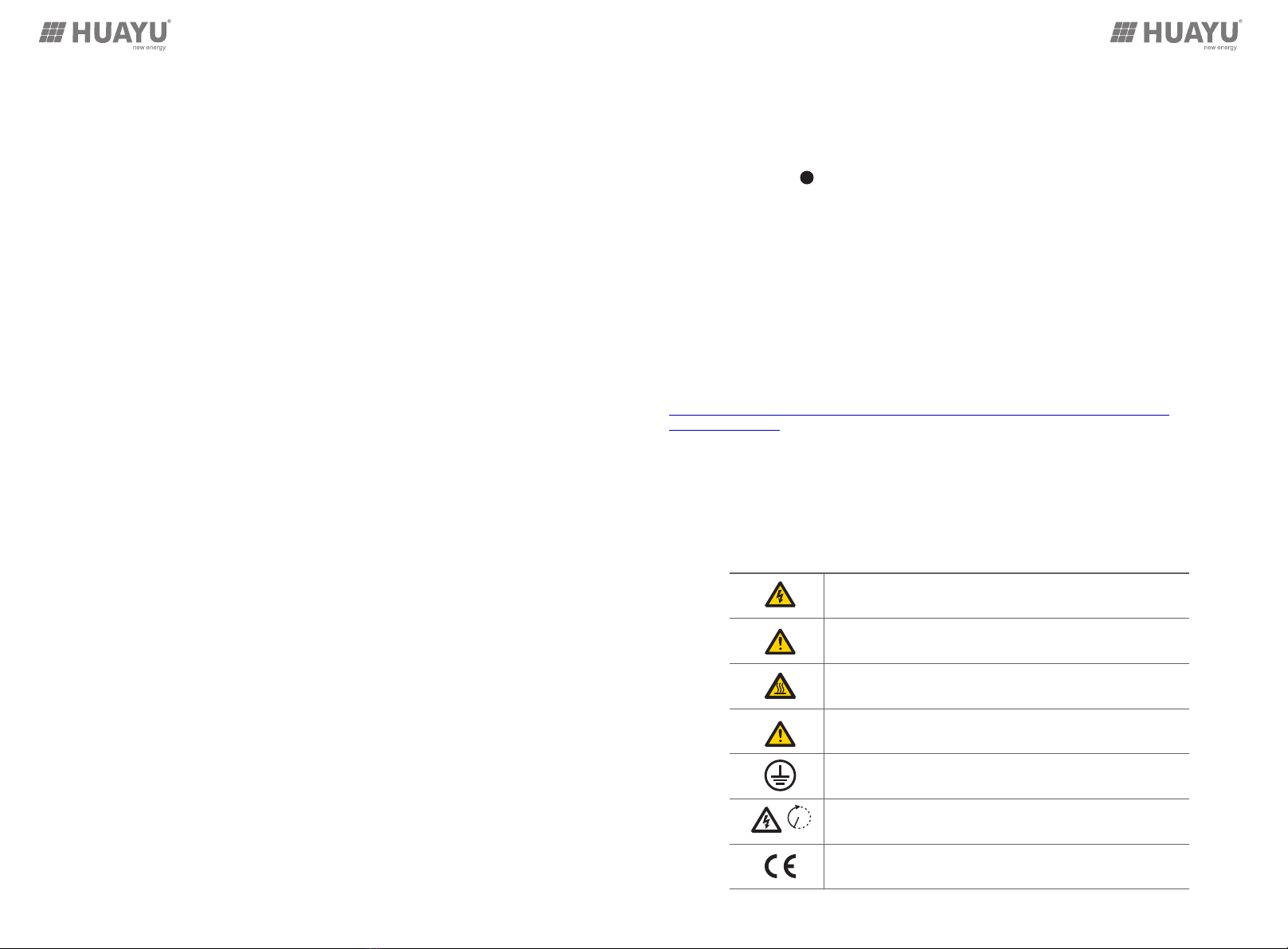
Before any wiring connection or electrical operation on inverter, all battery and AC power must be disconnected
from inverter for at least 5 minutes to make sure inverter is totally isolated to avoid electric shock.
During operation, the upper lid of the enclosure and the enclosure body may become hot. Only touch the lower
enclosure lid during operation, and make sure the inverter is untouchable for children
Usage and operation of the inverter must follow instructions in this user manual, otherwise any injury or damage
and warranty is not warranted by Huayu New Energy.
Do not open inverter's cover or change any components, otherwise the warranty commitment for the inverter will
be invalid.
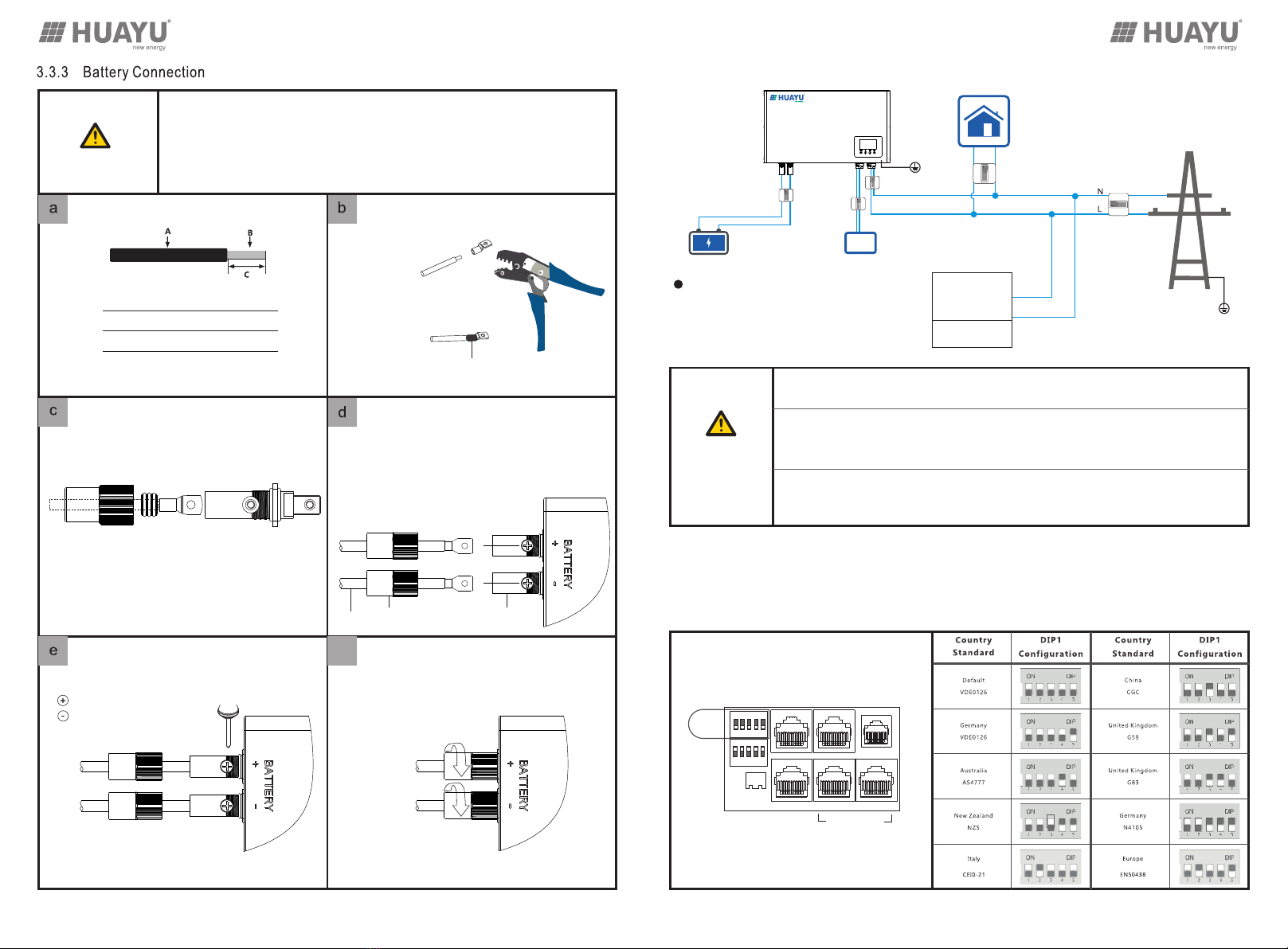
DC differential currents from battery are created , thus an external RCD (type A) can be used(30mA) in the AC
output of the HYH-3.6K-AC. As the HYH-3.6K-AC used with PV inverters in the system, so the PV inverters are
creating residual current too, in order to prevent unwanted triggering during operation, we recommend that the
rated residual current of the RCD has to be min 50mA.
In Australia, the inverter internal switching does not maintain neutral integrity, which must be addressed by
external connection arrangements like in the system connection diagram for Australia on page 8
2. Working Modes Introduction
MODE 1:
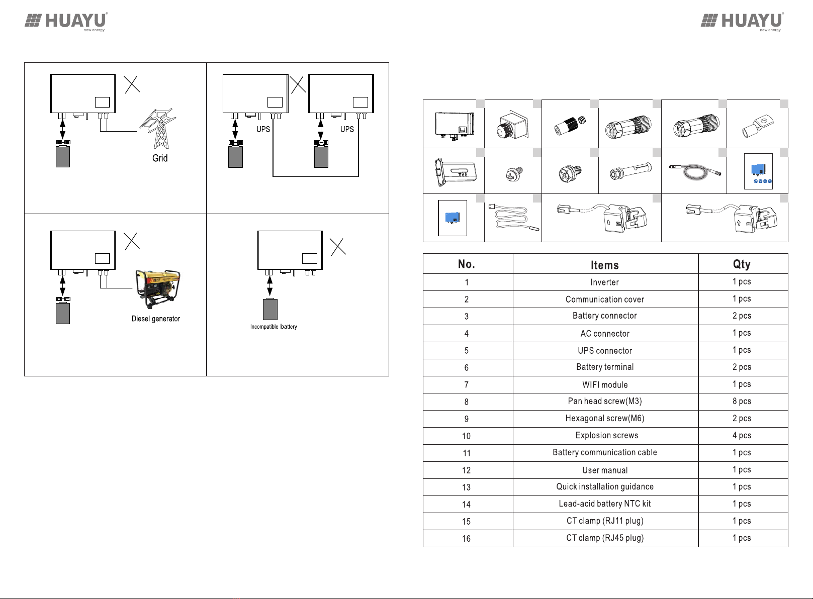
It is applied in the micro-grid system. During the day, the energy generated by the diesel generator is stored
in the battery, and the power is supplied to the load from the network at night. It is suitable for the micro-grid
environment that needs quiet electricity at night. In this mode, 10 units can be connected in parallel with a
power of 36kW.
HYH-3.6K-AC MICRO-GRID MODE:
0403
This mode needs special hardware
versionfirmwa and re version, please
contact to Huayu(Ning Bo)New Erengy
Technologies Co.,Ltd.
AC-Coupled energy storage inverter is designed for indoor and outdoor usage with existed
grid-connected solar power systems want to retrofit with batteries to store energy. It has five modes to
satisfy the PV+ Storage system
When PV power is sufficient enough with excess power
rested after supplying the loads, the excess power will
be firstly used to charge the battery by HYH-3.6K-AC,
if there is still power rested after that then it will be feed
-in to the grid.
When the PV power is not sufficient enough,
HYH-3.6K-AC discharges the battery power to
the household load, so that the power which is
taken from the grid as little as possible.
When grid power fails, immediately, the HYH-3.6K-AC
discharges the battery power to the important household
load using uninterrupted power supply technology which
will guarantee the power supply stability and continuously
of important loads. (Notice that it's required to enable the
UPS function to activate this working mode)
Battery can be charged by grid power (AC charge mode)
by enable relevant functions and make right settings
according to the real demands on the AC charge function
via LCD operation, monitoring website or the APP.
MODE 3: MODE 4:
HYH-3.6K-AC can be set to “Force Discharge” mode,
no matter PV inverter output energy is sufficient or not,
the HYH-3.6K-AC discharges the power to the grid and
Time &power &SOC limit can be set flexibly via LCD
operation, monitoring website or APP.
MODE 5:
MODE 2:
HYH-3.6K-AC HYH-3.6K-AC
HYH-3.6K-AC
HYH-3.6K-AC
HYH-3.6K-AC
HYH-3.6K-AC HYH-3.6K-AC
HYH-3.6K-AC

EPS side can’t connect to Grid
Without the micro-grid mode version hardware and
firmware, On-Grid or EPS side should not be connected
to any AC generator.
3. Installations & Connection
3.1 Packing List
Please check to make sure all the components as below are in good condition.
0605
Qu ick In stall ation
US ER MAN UAL
Batte ry
1 2 3 4 5 6
7 8 9 10 11 12
13 14 15 16
Forbidden System Connections
Without the micro-grid mode version hardware and
firmware, EPS side should not be paralleling connected.
If it is 48V pack, and no incompatible batteries could be
setting as lead-acid mode in LCD, website or the APP
HYH-3.6K-AC HYH-3.6K-AC HYH-3.6K-AC
HYH-3.6K-AC HYH-3.6K-AC

3.2 Installation
HYH-3.6K-AC GT Mode Communication Port
Product Overview and Connection Overview
Battery Input +
Battery Input -
Lead-acid Battery NTC
DRMS Input (Only for Australia)
PV Inverter CT
Grid CT
Lithium Battery Communication Port
SYSTEM CONNECTION DIAGRAMS
Inverter
EP S /UPS
Lo ad
Inve rte r
Batt ery
Sub Breaker
Main RCD Breaker
Sub RCD Breaker
Sub Breaker
Lithium Battery
Hoursehold Load
1 2 345
1 2 345
ON DI P
ON DI P
DIP1
DIP2
NTC
DRMS I nv ert er I nterf ac e
Batt er y
RS48 5/ CAN G ri d PV
PE
PE
0807
(I≥100ADC)
(I≥40A,In≥30mA)
Sub RCD Breaker
(In≥30mA)
(I≥40A,In≥30mA)
(In≥50mA)
Inverter
EP S /UPS
Lo ad
Inve rte r
Batt ery
Sub Breaker
Main RCD Breaker
Sub RCD Breaker
Sub Breaker
Lithium Battery
Hoursehold Load
1 2 345
1 2 345
ON DI P
ON DI P
DIP1
DIP2
NTC
DRMS I nv ert er I nterf ac e
Batt er y
RS48 5/ CAN G ri d PV
PE
PE
(I≥100ADC)
(I≥40A,In≥30mA)
Sub RCD Breaker
(In≥30mA)
(I≥40A,In≥30mA)
(In≥50mA)
For Australian safety country, the neutral cable of on-Grid side and Back-up side
must be connected, otherwise Back-up function will not work.
CAUTION!
General Connection
This diagram is for Australian and New Zealand grid system

j) Do not install the inverter in living area.
k) Do not install the inverter near TV antenna or other antenna or antenna cables.
l) Make sure there are enough space of the location for easy access to the inverter, relevant connection points
and switches in future operation and maintenance.
m) The height of installation should be reasonable to make sure easy operation and view the display of the inverter.
In order to prevent any electric shocks or other injuries, please make sure
there are no electricity, plumbing or gas pipeline in the wall where selected
to drilling holes for installation.
DANGER!
3.2.2 Clearance Requirements
To ensure the inverter working normally and easy to operate, there are requirements on available spaces of the
inverter, e.g. to keep enough clearance.
>900mm
>500mm
3.2.3 Installation the Inverter
To prevent potential damages and injuries from inverter falling down, please
carefully hang the inverter on the bracket, don't loosen grip unless confirm the
inverter is well mounted on the inverter.
CAUTION!
Step1: Position the machine's probably size onto the wall; the thickness of wall
for HYH-3.6K-AC at least 60mm.
Step2: Drill four Ф8 holes at the marked point, the depth is not less than 50mm
Step3: Knock four explosion screws into the holes
4*M6 Explosion Screws
10
Requirements
The HYH-3.6K-AC

Step4: Mount the inverter onto the four explosion screws
Step5: Lock the nut of setscrew and finish the inverter installation.
3.3 Connection
Make sure the inverter is totally isolated from any DC or AC power
before connection
CAUTION!
Cable Requirements: Uninstall the AC connector.
Confirm the L, N, PE Ports to the
Grid lines are correct
Lead the AC cable through cable gland, seal
ring and threaded sleeve, and fully insert the
conductors to corresponding terminals on
connection terminal and tighten the screws.
Assemble the AC connector and make sure
that the rib of the terminal block and the
groove on the housing engage perfectly.
Push threaded sleeve on to connection terminal
until both are locked tightly
A. Diameter 10~12 mm
B. Cross Section 3~4 mm²
C. Strip Length
10 mm
f
1211
Cable Requirements: Uninstall the UPS connector.
Confirm the L, N, PE Ports to the EPS load lines
are correct
Lead the UPS cable though cable gland, seal
ring and threaded sleeve, and fully insert the
conductors to corresponding terminals on
connection terminal and tighten the screws.
Assemble the UPS connector and make sure
that the rib of the terminal block and the groove
on the housing engage perfectly.
Push threaded sleeve on to connection terminal
until both are locked tightly
A. Diameter 10~12 mm
B. Cross Section 3~4 mm²
C. Strip Length
10 mm
f
Connection
termimal
Threaded
sleeve
Seal ring
Pressure
screw
Connection
termimal
Threaded
sleeve
Seal ring
Pressure
screw
M6 Explosion screw

A. Diameter 10~12 mm
B. Cross Section 20~25 mm²
C. Strip Length ~ 10 mm
Cable
Tighten
Waterproof Sleeve
Terminals
On Inverter
Red Cable
Tighten the waterproof sleeve perfectly and finished.
2*M6
Screws
Black Cable
Warning!
Polarity reverse will damage the inverter!
f
Crimp the OT terminal, install the heat shrinkable
casing
Lead the battery cable with OT terminal through
waterproof sleeve and cable rubber ring.
Connect positive pole (+) of battery cable to
battery positive terminal (+) of the inverter,
connect negative pole (-) of battery cable to
battery negative terminal (-).mind that the OT
terminals should be inverted into the battery
terminals on inverter
Using 2*M6 screws to tighten the positive terminal
(+) and battery negative terminal (-) on inverter
D:Accessories Battery terminal
3.3.4 Wiring the Whole System
1413
1. This part in this manual only describe the battery connection on inverter side, should
you need more detailed information regarding the battery connection on battery side
please refer to the manual of the battery you are using.
2. Mind that battery positive (+) and negative pole (-) reverse will damage the inverter
and battery.
CAUTION!
Inverter
EP S /UPS
Lo ad
DC Breaker
Main RCD Breaker
Sub RCD Breaker
Sub RCD Breaker
Lithium Battery
Hoursehold Load
PE
PE
RCD Breaker
(I>100ADC)
Connecting the AC output of HYH-3.6K-AC
to the grid, and connecting the EPS output of
HYH-3.6K-AC to the important load as the
above wiring diagram.
1.An external RCD breaker can be used(I≥40A,In≥30mA) in the EPS output of the
HYH-3.6K-AC and the input of household Load.
2.As the HYH-3.6K-AC used with PV inverters in the system, so the PV inverters are
creating residual current too, in order to prevent unwanted triggering during operation,
we recommend that the rated residual current of the Main RCD Breaker has to be ≥50mA.
3.The AC breaker in the Grid output of the HYH-3.6K-AC is suggested to be ≥40A.And
the DC breaker of the battery is suggested to be ≥100A.For batteries with attached switch,
the external DC switch is not necessary.
CAUTION!
NOTE: For Australian and New Zealand safety country, the neutral cable of On-Grid side and Back-Up side must
be connected together, please refer to page 8: the wiring diagram for Australian and New Zealand grid system.
tube
(I≥40A,In≥30mA)
(In≥30mA)
(In≥50mA)
(I≥40A,In≥30mA)
3.3.5 Setting Safety Standard
Setting safety with DIP1 dial switch as below:
1 2 345
1 2 345
ON DIP
ON DIP
DIP1
DIP2
NTC
Grid PV
Battery
RS485/CAN
DRMS Inverter Interface
Setting DIP1 and DIP2 configurations.

Rubber stopper
Cable gland

Waterproof cover
Anti-slip fence
Step3: Put the Battery communication cable(lithium battery ) / “NTC” (lead-acid battery ) and CT cables cross
into the cable gland, anti-slip fence, rubber stopper, waterproof cover one by one.
Cables
Cable
gland
Rubber
stopper
Anti-slip
fence
Waterproof
Cover
Rj45
Plugs
Inverter side
18
Pin1:RS485-A
Pin2:RS485-B
Pin3:CAN-L
Pin4:CAN-H
Inverter
Step4: Insert the Rj45 plug of the network cable into the
“RS485" place inverter until it snaps.
Step5: Lock the Rj45 waterproof cover with the combination
4*M4 screws and finished.
Step6: Lock the RJ45 waterproof cover with the
combination 4*M4 screws and finished.
Step7: If lithium battery connecting the Battery communication cable the side with label of “Battery”(lithium
battery ) to the lithium battery communication port .If lead-acid battery, just let the NTC near the lead-acid
battery surface.
Step8: Catching the CT1 to the grid L line from grid and the direction is “Grid→House”.
Catching the CT2 to the grid L line of the inverter output.
Battery NTC
(only for lead acid battery)
Using four M3 screws to screw the
WIFI MODE to the inverter.
1817
3.3.7 Install Wifi Module
Step1Unscrew the swivel nut from the cable gland Step2Remove 3 plug-columns from the rubber
stopper and others reserved
NOTE: For Australian and New Zealand safety country, the neutral cable of On-Grid side and Back-Up side must
be connected together, please refer to page 8: the wiring diagram for Australian and New Zealand grid system.
Inverter
EP S /UPS
Lo ad
Inve rte r
Batt ery
Sub Breaker
Main RCD Breaker
Sub RCD Breaker
Sub Breaker
Lithium Battery
Hoursehold Load
1 2 345
1 2 345
ON DI P
ON DI P
DIP1
DIP2
NTC
DRMS I nv ert er I nterf ac e
Batt er y
RS48 5/ CAN G ri d PV
PE
PE
(I≥100ADC)
(I≥40A,In≥30mA)
Sub RCD Breaker
(In≥30mA)
(I≥40A,In≥30mA)
(In≥50mA)
General Connection
Rubber stopper
Cable gland

4. Display, Setting And Operation
4.1 LCD Overview and Brief Introduction
This type LCD screen contains the system information display and setting functions, the overview of the
LCD screen is shown below:
Download
ID Auto Test
Screen Interface Instruction:
No. Description Remarks
Generally information
display area
This area will display the currently time/date by default (year: month:
day, and hour: minute” switching automatically). When press Up or
Down buttons, this area will display the firmware version information,
serial number etc.
On-grid solar inverter out-
put power and energy data
This area shows only the data monitored by the Huayu AC-coupled inverter
through the CT clamp installed at the existed on-grid solar inverter output
side.
Battery information
and data
This area shows the battery type, battery brand (lithium battery), and
displays the voltage, SOC and power in turns of period of 1 seconds.
System working status There are three type of working status – normal, warning and fault, in
right side of this area, there are code display, it will display different type
of code – the system working mode code, warning code and fault code.
2019
1
2
3
4
UPS/EPS output
information and data
When UPS function is enabled, this area will display UPS voltage,
frequency, power etc. in turns of periods of 1s.
5
6
7
8
Programming and Auto Test When Auto Test process is occurring (only for Italy standard) or firmware
updating in process, it will display relevant information.
Loads consumption Display the power consumption by the loads
Grid information Display the grid information of voltage, frequency, input or output power,
switch period of 1s
Working mode settings area When make settings on the Huayu AC-coupled inverter through the LCD, this
area will display the AC Charge, Force Discharge, Charge First option
for setting on those working modes. It will not display those information
unless in the setting process.
Touch buttons Return, Up, Down and Enter touch button for operation through the LCD.
WiFi Module connection
signal
When WiFi module is connected to Huayu AC-coupled and the
communication between them is normal, this signal will displayed in this
area.
9
10
11
4.2 General Information Checking and Settings
4.2.1 General Information Display
When the LCD automatically displays the system general information, it will display as below image shows:

4.2.2 Start the Settings
When the system is not in Auto Test or Programming status, then please press Return button access into the
setting process:
When pressed Return button the area 1 (for time setting) will flashing at the start, you can press UP and Down
buttons to select what to set, and then press Enter button to start the settings on selected setting options.
4.2.3 Time Settings
To set the time of the Huayu AC-coupled inverter, please follow below steps:
Download
ID Auto Test
Set the Year:
When the display area ①will flashing, press Enter button to set the year, press UP and Down buttons to change
the year number, and press Enter button to confirm and finish the year setting.
Down
UP
2221
Set the Month:
When finished the years setting then the month number will flashing, press UP and Down buttons to change the
month number, and press Enter button to confirm and finish the month setting.
Down
UP
Set the Day:
When finished the months setting then the day number will flashing, press UP and Down buttons to change the
day number, and press Enter button to confirm and finish the day setting.
Set the Hour:
When finished the days setting then the hour number will flashing, press UP and Down buttons to change the
hour number, and press Enter button to confirm and finish the hour setting.
Down
UP
Down
UP
Set the Minute:
When finished the hours setting then the minute number will flashing, press UP and Down buttons to change the
minute number, and press Enter button to confirm and finish the hour setting.
Down
UP
After confirmed and finished the hour setting, the area ① will still flashing, you can press Return button to exist
the setting process, or press UP and Down buttons to select other setting options, or press Enter button to set
the time again.

4.2.4 Battery Settings
Press Return button, then press UP or Down buttons to select area ③ (when area ③ is flashing), then press Enter
button to start the battery settings.
Download
ID Auto Test
Press Enter button to select battery type ( Lead-Acid or Li-ion).
For Lead-Acid Battery:
select the Lead-Acid option and then press Enter button to confirm the battery type, then the following battery
capacity area (50Ah) will flash then please select the lead-acid battery capacity by pressing the UP and Down
buttons, the lead-acid battery capacity could be 50Ah, 100Ah, 150Ah, 200Ah and 250Ah. Then press Enter
button to confirm and finish the lead-acid battery settings.
For Lithium-ion Battery:
Select the Li-ion option and press Enter button to confirm the battery type, then the battery brand area will
flashing, press UP and Down button to select the battery brand number ( see the list battery brand number
table), and press Enter button to confirm and finish the lithium-ion battery settings.
BAT. Brand number Battery Brand
Reserve
0
1
2
3
4
5
6
...
Reserve
Pylon Tech
Reserve
Reserve
Reserve
Reserve
...
4.2.5 UPS Settings
To use the UPS (sometimes regarded as EPS or back-up function) function, it must be enabled through the
UPS settings.
Download
ID Auto Test
2423

Press Return button to get into setting mode, then press UP and Down button to select the area ⑤
(when area ⑤ is flashing), then press Enter button to start the UPS settings.
Enable/Disable UPS Function:
Press UP and Down buttons to select the Disable or Enable option when they are flashing, and press Enter
button to enable or disable the UPS function.
Down
UPS Voltage Settings:
When enabled the UPS function, then the UPS voltage area will flash, press UP and Down buttons to select the
UPS voltage to be 220V or 230V and then press Enter button to confirm and finish the UPS voltage settings.
UPS Frequency Settings:
When confirmed and finished the UPS voltage settings, then the UPS frequency area will flash, press UP and
Down buttons to select the UPS frequency to be 50Hz or 60Hz and press Enter button to confirm and finish
the UPS settings.
4.2.6 AC Charge Settings
Download
ID Auto Test
Press Return button to get into setting mode, and press UP and Down button to select the AC Charge option of
area ⑨ is flashing, then press Enter button to start the AC charge settings.
Enable/Disable AC Charge Function:
Press UP and Down buttons to select the Enable or Disable options of AC charge settings to enable or disable
this function, and press Enter button to confirm to enable or disable AC charge function.
2625
Down

2827
AC Charge Power Limit Rate Settings:
When enabled the AC charge function, it will turn to the setting of AC charge power limit rate settings which
means to set the AC charge power rate against the maximum AC output/input power. Press UP and Down
buttons to select the AC charge power limit rate (from 0%~100%), and then press Enter button to confirm and
finish the power limit rate setting.
Power
%
AC Charge SOC Limit Rate Settings:
When confirmed and finished the AC charge power limit rate settings, it will turn to the battery AC charging
SOC limit rate settings which means to set the SOC limitation which once SOC is above this set rate then
stop AC charging. Press UP and Down buttons to select the SOC limit rate (from 0% ~100%), and then press
Enter button to confirm and finish the SOC limit rate settings.
%SOC
AC Charge Time Settings:
When confirmed and finished the AC charge SOC limit rate settings, it will turn to the AC charge time settings.
To set the firs AC charge time period, press UP and Down buttons to select the AC charge start time 1 and
press Enter button to confirm it, then set the AC charge end time 1 and press Enter button to confirm and finish
the AC charge time period 1 settings, and it will turn to AC charge time period 2 settings and AC charge time
period 3 settings, or you can press Enter button for 8 times to get over the time period 2 and 3 settings if you
don't want set them.
Start
End
4.2.7 Force Discharge Settings
If the system has to change the working modes to forced discharge the battery stored energy, then we need
to enable the Force discharge function and make settings.
Press Return button to get into setting mode, and press UP and Down button to select the Force Discharge
option of area ⑨ is flashing, then press Enter button to start the force discharge settings.
The rest of setting of Force Discharge is the same as AC Charge settings.
4.3 The Working/Warning/Fault Code Explanation
The system working status will be displayed in area ④, in ways of face icons and status code. Below are the Code
explanation for HYH-3.6K-AC:
Status Code Inverter Status Remarks
Standby
Fault
Programming
Battery discharge (grid tied)
AC charge
Battery discharge (off-grid)
Battery discharge when on-grid
Charge battery use grid power
Battery discharge when off-grid
0
1
2
16
32
64
5. Start UP and Shutdown
5.1 Start-UP the HYH-3.6K-AC System
Users can start-up HYH3.6K-AC through following steps
Step1:Turn on the grid side AC circuit breaker to connect to Grid
Step2:Turn on the battery side DC circuit breaker to connect to Battery
Step3:When the working information is displayed on LCD screen and the icon of the battery is flashing,
then set the type of the battery and finish, the inverter will restart after the setting.
Step4:When the working information is displayed on LCD again and the battery is not flashing, it means that the
HYH-3.6K-AC system is starting up successfully.
5.2 Shut-down the HYH-3.6K-AC System
Step1:Turn off all the circuit breakers and switches, make sure that the grid connection, battery connection,
PV connection and UPS connection are all disconnected by turning off the relevant breakers and switches.
Step2:Wait for 5mins and the HYH-3.6K-AC is shut down completely

UPS short circuit
UPS power reversed
1.Check UPS L,N connection.
2.Disconnect the UPS connector,
if the error still exist, contact us.

Add:No.456 Xingning Road, Ningbo 315100, P.R.China
Contact Huayu(Ningbo)New Energy Technologies Co., Ltd.
Add:+86-574-8925 8801
Mail: info@huayu-energy.com
Web: www.huayu-solar.com
As the manufacturer of this inverter, we provide the manufacturer warranty to our products
to our users. For detailed information please refer to the warranty card in the packaging of
the inverter or contact our service center via email, web message or phone call.
HYH-3.6K-AC
Table of contents
Other Huayu Inverter manuals