Hubbell GAI-TRONICS 234 User manual

Pub. 42004-194H
GAI-Tronics Corporation P.O. Box 1060, Reading, PA 19607-1060 USA
610-777-1374 800-492-1212 Fax: 610-796-5954
VISIT WWW.GAI-TRONICS.COM FOR PRODUCT LITERATURE AND MANUALS
GAI-TRONICS® CORPORATION
A HUBBELL COMPANY
Model 234 Stanchion Assembly
Confidentiality Notice
This manual is provided solely as an installation, operation, and maintenance guide and contains sensitive
business and technical information that is confidential and proprietary to GAI-Tronics. GAI-Tronics
retains all intellectual property and other rights in or to the information contained herein, and such
information may only be used in connection with the operation of your GAI-Tronics product or system.
This manual may not be disclosed in any form, in whole or in part, directly or indirectly, to any third party.
Introduction
The complete emergency station is shipped in two stages. The Model 84504 Hardware Kit is usually
shipped in advance followed by the remaining assemblies (Model 84501, Model 84502, and Model
84503). In addition to this publication, refer to the following manuals to assist in properly installing a
complete station:
Pub. No. Emergency Phone Model
Pub. 42004-284 Model 530FB Strobe with Dual Constant-On Lamps
Pub. 42004-352 Model 297-001 Flush-Mount Emergency Phone
Pub. 42004-351 Model 297-003 S.M.A.R.T. Flush-Mount Emergency Phone
Pub. 42004-352 Model 298-001 Flush-Mount Emergency Phone with Keypad
Pub. 42004-351 Model 298-003 S.M.A.R.T. Flush-Mount Emergency Phone with Keypad
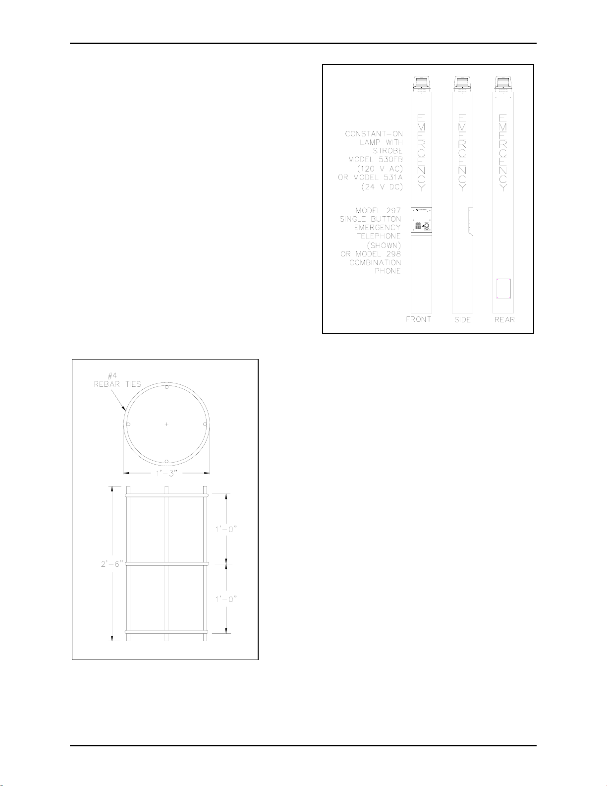
The Model 234 Stanchion Assembly is designed to house a Model 298 or 297 Emergency Telephone and
a Model 530FB or 531A Beacon. This aesthetically-pleasing stanchion is over 9 feet tall, making it easily
located by potential users.
The beacon creates added noticeability to emergency telephone locations by providing a constant-on lamp
and a flashing strobe light is automatically engaged when the emergency button is pressed. The telephone
is also highly visible; a light mounted in the stanchion shines on the front panel of the telephone to
illuminate the phone for nighttime use.
GAI-Tronics enhanced emergency telephones are designed for isolated high-risk areas requiring
emergency communications equipment.
Emergency telephone users simply press the clearly labeled emergency push button for immediate
connection to a user-programmed central security telephone number.

Pub. 42004-194H
Model 234 Stanchion Assembly Page: 2 of 11
d:\standard ioms - current release\42004 instr. manuals\42004-194h.doc
09/05
Mounting
A concrete pier is required to support the stanchion.
GAI-Tronics provides the Model 84504 Hardware Kit
to aid with the construction of this pier.
We recommend using as a minimum, 3,000 psi grade
concrete. The pier must be strong enough to support a
structure that is 9 1/2-feet tall and weighs 225 lbs.
Reinforcement Cage
We recommend that the concrete base be 3 feet deep
and 18 inches wide, and that a reinforcement cage be
used. The reinforcement cage is not provided by
GAI-Tronics. The following materials are necessary
to construct the reinforcement cage:
•four #4 rebars;
•three #4 ties;
•one 18-inch sonotube.
1. Construct the reinforcement cage by placing a horizontal
member in the center of the rebar.
2. Place the two remaining horizontal members 12 inches
from that center point. See Figure 2. The top of the
cage should be 3 inches below the top of the pier.
3. The reinforcement cage in Figure 2 shows the maximum
diameter that is suitable for a customer-provided 18-inch
sonotube.
4. Install two conduits in the pier—one for the telephone
wire and one for the electrical power wire.
NOTE:These conduits MUST be kept separate to
prevent interference from occurring on the audio lines.
Conduits are not supplied by GAI-Tronics.
Figure 1. Complete Emergency Station
Figure 2. Reinforcement Cage

Pub. 42004-194H
Model 234 Stanchion Assembly Page: 3 of 11
d:\standard ioms - current release\42004 instr. manuals\42004-194h.doc
09/05
Installation
ATTENTION Installation should be performed by qualified personnel and only in
accordance with the National Electrical Code and applicable local codes.
The following information provides guidelines on the installation of various components of the
emergency station. Grounding electrode conductor (not depicted in the illustration) must be constructed
in accordance with the National Electrical Code and applicable local codes.
Model 84504 Hardware Kit Installation
The Model 84504 Hardware Kit includes four anchor bolts, which should be installed so that they extend
3 inches above the top of the pier surface. See Figure 3.
Use the template provided in the hardware kit for anchor bolt positioning, or see Figure 4 for dimensions.
The 3-inch leg of the anchor bolts should point to the center of the tube. Center lines should be measured
across the corners.
Figure 3. Front View

Pub. 42004-194H
Model 234 Stanchion Assembly Page: 4 of 11
d:\standard ioms - current release\42004 instr. manuals\42004-194h.doc
09/05
NOTE:The stanchion should not be mounted until the concrete has been allowed to cure for a minimum
of 24 hours.
Figure 4. Top View

Pub. 42004-194H
Model 234 Stanchion Assembly Page: 5 of 11
d:\standard ioms - current release\42004 instr. manuals\42004-194h.doc
09/05
Model 84501 Stanchion Main Body Installation
1. If the concrete is not level, find the anchor rod at the highest point of the concrete, and screw one
¾-inch heavy hex nut 1-1/8 inches above the concrete surface (measuring to the top of the nut).
See Figure 5.
2. Adjust the remaining three hex nuts to be level with the first. Place one washer over each heavy hex
nut. See Figure 5 and Figure 6.
3. Before mounting the stanchion, unscrew the four tamper-resistant screws on the rear handhole cover,
and remove the cover.
4. Apply a small amount of clear RTV silicone sealant or equivalent to each screw thread to reduce the
possibility of rust forming in the screw threads.
NOTE:GAI-Tronics Model 233 Tamper-Resistant Screwdriver is required to remove
tamper-resistant screws.
5. Place the stanchion on top of the four level, heavy hex nuts.
6. Entering through the rear handhole, place the four remaining washers on the anchor bolts, and secure
with the ¾-inch hex nuts. Do not install the handhole cover until the wiring is complete.
Figure 5. Exploded View

Pub. 42004-194H
Model 234 Stanchion Assembly Page: 6 of 11
d:\standard ioms - current release\42004 instr. manuals\42004-194h.doc
09/05
NOTE:A ¼-inch air gap must exist between the base of the stanchion and the top of the concrete pier.
See Figure 6. This air gap must not be obstructed with soil, mulch, stone, etc.
The unit should be installed and grounded in accordance with national and local electrical codes.
NOTE:A grounding stud connection has been provided inside the rear access panel.
Figure 6. Assembled View

Pub. 42004-194H
Model 234 Stanchion Assembly Page: 7 of 11
d:\standard ioms - current release\42004 instr. manuals\42004-194h.doc
09/05
Model 84503 Stanchion Panel Light Installation
1. Remove the two screws securing the bezel and lens to the
stanchion panel light assembly.
2. Align the stanchion panel light assembly inside the
stanchion as shown in Figure 7.
3. Extend the black (hot) and the white (neutral) wires to the
base of the stanchion (these wires will be connected later,
along with the beacon wires, to the incoming power wires
in accordance with the electrical codes).
4. Secure the light assembly with the two mounting screws
provided. Apply a small amount of clear RTV silicone
sealant or equivalent to each screw thread to reduce the
possibility of rust forming in the screw threads.
5. Insert the 7-watt compact fluorescent bulb provided with
the assembly.
6. Secure the bezel and the lens to the stanchion.
Figure 7. Stanchion Panel
Light Assembly

Pub. 42004-194H
Model 234 Stanchion Assembly Page: 8 of 11
d:\standard ioms - current release\42004 instr. manuals\42004-194h.doc
09/05
Model 530FB or 531A Beacon and Model 84502 Strobe Installation
1. Insert the beacon’s seven 15-foot wires through the stanchion’s threaded nipple, and allow the wires
to extend to the base of the stanchion. See Figure 8.
2. Screw the beacon onto the threaded nipple. Secure the lens cover (Model 84502) with four
tamper-resistant screws.
3. Apply a small amount of clear RTV silicone sealant or equivalent to each screw thread to reduce the
possibility of rust forming in the screw threads.
4. Separate the orange and violet wires necessary for the telephone connection, and extend those wires
through the stanchion cutout for the telephone.
Figure 8. Beacon Assembly

Pub. 42004-194H
Model 234 Stanchion Assembly Page: 9 of 11
d:\standard ioms - current release\42004 instr. manuals\42004-194h.doc
09/05
Emergency Telephone Installation
1. Separate the back box from the front panel of the telephone. Inside the back box is a parts envelope
is containing eight 6-32 self-tapping flat head screws, six tamperproof screws, six washers, and a hole
plug.
2. Place the back box into the phone opening from the front of the stanchion. Mount the box using four
of the 6-32 self-tapping flat head screws. The telephone back box has an opening in the top and one
in the bottom. Plug the top opening with a hole plug. The bottom of the back box is the
recommended entry location for the telephone line and strobe control wires.
3. Install a telephone line surge suppressor (sold separately) on the protection bracket on the bottom of
the stanchion wall mounting assembly.
4. Install a ground wire between the telephone line surge suppressor (sold separately) and the grounding
lug on the bottom of the stanchion. See Figure 9.
5. Connect the telephone line to the surge suppressor Figure 9.
Figure 9. Interconnection with ac beacon
6. Connect the telephone cable from the surge suppressor, and feed the cable through the bottom access
hole of the telephone back box and allow it to hang free.
7. Bring the orange and violet strobe unit wires through the bottom access hole of the back box, and
allow them to hang free.
8. The telephone front panel is shipped from the factory with a cable and modular plug attached to TB1.
If the telephone line is to be hard-wired to the phone, this cable can be removed and discarded. Skip
to Step 9. If desired, an optional modular telephone jack can be mounted to the inside of the back box
allowing the use of the cable and modular plug that is attached to TB1.

Pub. 42004-194H
Model 234 Stanchion Assembly Page: 10 of 11
d:\standard ioms - current release\42004 instr. manuals\42004-194h.doc
09/05
9. Attach the telephone cable from the surge suppressor to TB1 on the telephone PCBA as shown in
Figure 9.
10. Attach the strobe’s violet and orange control wires to TB2 on the telephone PCBA as shown in Figure
9.
Install the phone’s front panel using the six tamper-resistant screws and six washers provided.
NOTE:Excessive tightening will cause the panel to warp. Do not over-tighten.
Wiring Power Connections
All wiring connections should be complete at this point, with the exception of the stanchion panel light
and beacon wire connections to the incoming power lines. All connections must be made in accordance
with the National Electrical Code (NEC) in the United States or the Canadian Electrical Codes (CEC) in
Canada. Install the power lines as follows:
1. Install the recommended ac power line surge suppressor on the protection bracket.
2. Install a ground wire between the telephone line surge protection and the grounding lug.
3. Connect the incoming ac power line to the surge protection as shown in Figure 9.
4. Connect the red, white, and green wires of the Model 530FB AC Beacon to the surge protection as
shown in Figure 9. When using the Model 531A DC Beacon, connect the red and white wires to the
dc power source as shown in Figure 10.
5. Connect the black, white, and green wires of the telephone light to the surge protection.
Figure 10. Interconnection diagram with dc beacon
After making these connections according to the prevailing electrical codes, replace the handhole cover at
the stanchion base using tamper-resistant screws.

Pub. 42004-194H
Model 234 Stanchion Assembly Page: 11 of 11
d:\standard ioms - current release\42004 instr. manuals\42004-194h.doc
09/05
Repairing Surface Damage to Powder Coated Stanchions
Scratch Repair
1. Carefully sand the damaged area to clean and score the base metal, taking care to minimize any
additional damage to the surrounding powder coating.
2. Wipe the sanded area with a cleaning solvent, such as DuPont “PrepSol.” Allow the area to dry. This
type of product is available at auto parts stores. Denatured alcohol may also be used.
3. Prepare the bare metal surface for painting by treating it with phosphoric acid solution intended for
this purpose. Allow the area to dry.
4. Using a cotton swap or small brush, paint the prepared surface with an automotive enamel or oil base
polyurethane enamel such as Red Devil or Rustoleum. DO NOT USE Krylon-type paints. Carefully
blend the repair enamel into the powder coat at the edges.
NOTE: EXACT color matches may not be attainable.
Decal Repair
1. Use a sharp instrument, such as an X-Acto knife, to loosen and lift a corner edge of the damaged
decal.
2. Carefully peel back and remove the loosened decal.
3. Wipe the area clean with denatured alcohol. Allow the area to dry.
4. Prior to attaching a new decal, dampen the target area with a fine mist of water (fine spray from a
plant misting bottle is ideal).
5. Peel the backing from the replacement decal, leaving the decal attached to the front cover material,
and carefully align it with the target area.
6. With the cover material still attached, press the replacement decal in place, then squeegee any water
from under the new decal starting at the center and working toward the edges.
7. Peel off the cover material, being careful not to tear or lift the decal. If the decal lifts as the cover
material is being removed, push down on the uncovered decal, and squeegee as necessary to remove
any large bubbles; small bubbles will disappear as the decal dries.
Specifications
Dimensions ..................................................................10 W ×10 D ×114 H inches (0.25 ×0.25 ×2.89 m)
Wall thickness............................................................................................................3/16-inch hot-rolled steel
Finish ...................................................................................................................................... Powder-coated
Power rating (telephone light) ...................................................................................120 V ac input/0.2 amp
Approvals:
UL/cUL listed OUTDOOR telephone stanchion...........Canadian Electrical Code, Part I (CE Code, Part I),
and the ANSI/NFPA 70 National Electrical Code (NEC).

(Rev. 1/97)
Warranty
Equipment.GAI-Tronics warrants for a period of one (1) year from the date of shipment, that any
GAI-Tronics equipment supplied hereunder shall be free of defects in material and workmanship, shall
comply with the then-current product specifications and product literature, and if applicable, shall be fit
for the purpose specified in the agreed upon quotation or proposal document. If (a) Seller’s goods prove
to be defective in workmanship and/or material under normal and proper usage, or unfit for the purpose
specified and agreed upon, and (b) Buyer’s claim is made within the warranty period set forth above,
Buyer may return such goods to GAI-Tronics nearest depot repair facility, freight prepaid, at which time
they will be repaired or replaced, at Seller’s option, without charge to Buyer. Repair or replacement shall
be Buyer’s sole and exclusive remedy, and the warranty period on any repaired or replacement equipment
shall be one (1) year from the date the original equipment was shipped. In no event shall GAI-Tronics
warranty obligations with respect to equipment exceed 100% of the total cost of the equipment supplied
hereunder. Buyer may also be entitled to the manufacturer’s warranty on any third-party goods supplied
by GAI-Tronics hereunder. The applicability of any such third-party warranty will be determined by
GAI-Tronics.
Services. Any services GAI-Tronics provides hereunder, whether directly or through subcontractors,
shall be performed in accordance with the standard of care with which such services are normally
provided in the industry. If the services fail to meet the applicable industry standard, GAI-Tronics will,
for a period of one (1) year from the date of completion, re-perform such services at no cost to Buyer. Re-
performance of services shall be Buyer’s sole and exclusive remedy, and in no event shall GAI-Tronics
warranty obligations with respect to services exceed 100% of the total cost of services provided
hereunder.
Warranty Periods. Every claim by Buyer alleging a defect in the goods and/or services provided
hereunder shall be deemed waived unless such claim is made in writing within the applicable warranty
periods as set forth above. Provided, however, that if the defect complained of is latent and not
discoverable within the above warranty periods, every claim arising on account of such latent defect shall
be deemed waived unless it is made in writing within a reasonable time after such latent defect is or
should have been discovered by Buyer.
Limitations / Exclusions. The warranties herein shall not apply to, and GAI-Tronics shall not be
responsible for, any damage to the goods or failure of the services supplied hereunder, to the extent
caused by Buyer’s neglect, failure to follow operational and maintenance procedures provided with the
equipment, or the use of technicians not specifically authorized by GAI-Tronics to maintain or service the
equipment. THE WARRANTIES AND REMEDIES CONTAINED HEREIN ARE IN LIEU OF AND
EXCLUDE ALL OTHER WARRANTIES AND REMEDIES, WHETHER EXPRESS OR IMPLIED
BY OPERATION OF LAW OR OTHERWISE, INCLUDING ANY WARRANTIES OF
MERCHANTABILITY OR FITNESS FOR A PARTICULAR PURPOSE.
Return Policy
If the equipment requires service, contact your Regional Service Center for a return authorization number
(RA#). Equipment should be shipped prepaid to GAI-Tronics with a return authorization number and a
purchase order number. If the equipment is under warranty, repairs or a replacement will be made in
accordance with the warranty policy set forth above. Please include a written explanation of all defects to
assist our technicians in their troubleshooting efforts.
Call 800-492-1212 (inside the USA) or 610-777-1374 (outside the USA) for help identifying the
Regional Service Center closest to you.
Table of contents
Other Hubbell Industrial Equipment manuals

Hubbell
Hubbell TredTrak User manual

Hubbell
Hubbell GFP20FWM User manual

Hubbell
Hubbell Chance PSC6010348 User manual

Hubbell
Hubbell DUAL LITE SPectron User manual

Hubbell
Hubbell Killark UGFI Series Instruction Manual

Hubbell
Hubbell CFB2G25R User manual

Hubbell
Hubbell KILLARK EYS Instruction Manual

Hubbell
Hubbell Killark ENY Series Instruction Manual

Hubbell
Hubbell HBL6750TFIV User manual

Hubbell
Hubbell CFBS1R8CVR User manual