5
©2021 Hubbell Incorporated | PSP8620311 Versa-Tech® VTI & VTLT Instruction Manual
REV G
Introduction
This manual is to guide you
through the programming,
installation, operation and
maintenance of the Versa-Tech®
I & LT single-phase reclosers.
This manual does not claim to
cover all situations that may arise
during installation. If additional
information is needed, contact
your factory representative. Nor
does this manual supersede
your company’s established
guidelines and practices for
similar equipment. Take note of
and heed all danger, warning
and cautions contained in this
document.
Qualified Person
Only qualified, trained, and com-
petent personnel that understand
proper safety procedures must
select, install and service this
equipment.
Read and understand these
instructions before installing,
operating or maintaining this
equipment.
This guide is not a substitute for
adequate training and experience
in safety procedures for this type
of equipment.
Signal Words
The signal words "DANGER",
"WARNING" and "CAUTION"
(along with their assigned
symbol) throughout this manual
indicate the degree of hazard
the user may encounter. These
symbols are described as:
DANGER indicates an imminently
hazardous situation which, if not
avoided, will result in death or
serious injury.
WARNING indicates a potentially
hazardous situation which, if not
avoided, could result in death or
serious injury.
CAUTION indicates a potentially
hazardous situation which, if not
avoided, may result in minor or
moderate injury.
CAUTION
CAUTION used without the
safety alert symbol indicates a
potentially hazardous situation
which, if not avoided, may result
in property damage.
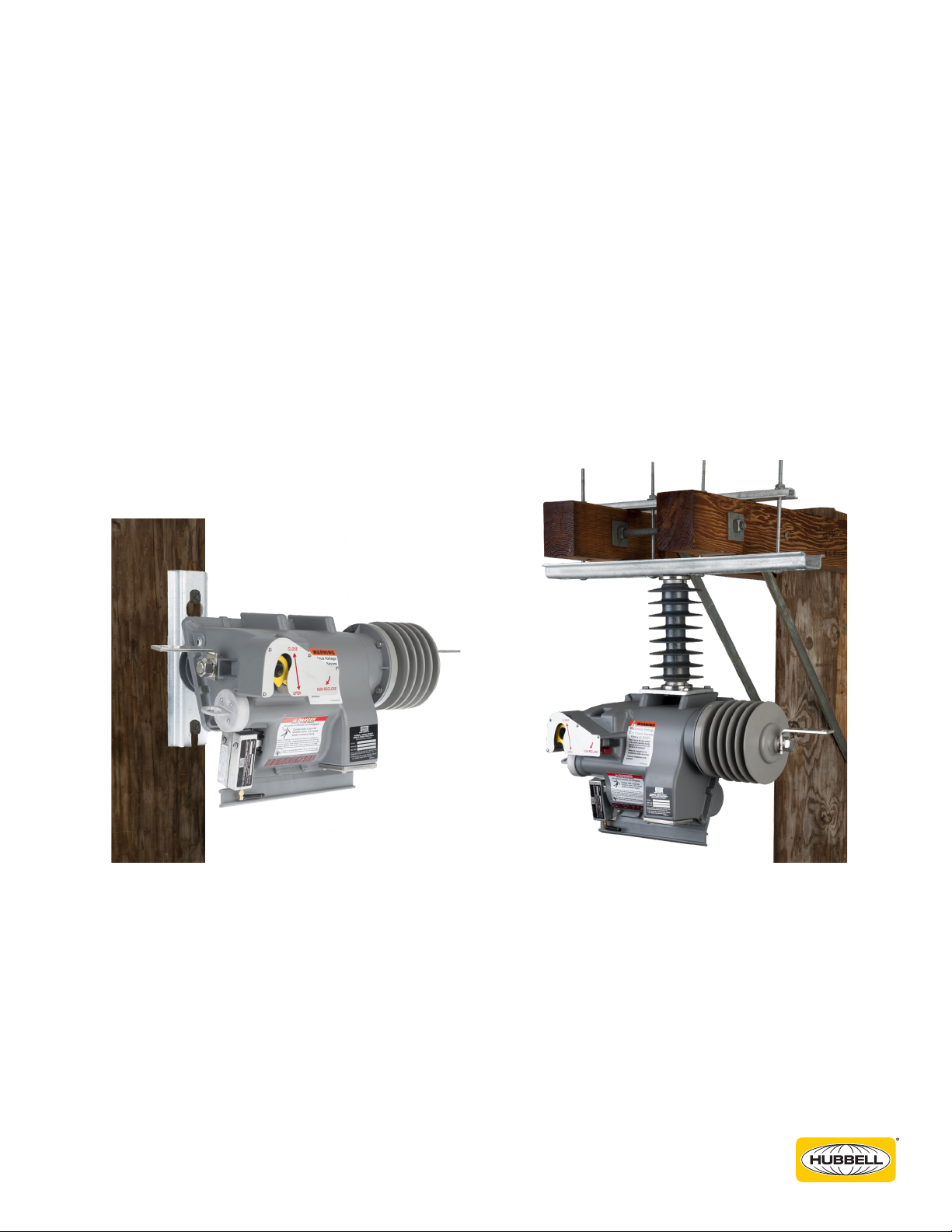
Product
The products covered by this
manual are the Versa-Tech® I
& LT single-phase reclosers
for medium voltage electrical
distribution circuits.
These products are designed for
distribution circuits only at their
rated capacities. They cannot be
field modified for capacities other
than what was shipped with the
units.
Function
This product is a single-phase
recloser designed to provide
a means for interrupting and
isolating faults on electrical
distribution systems.
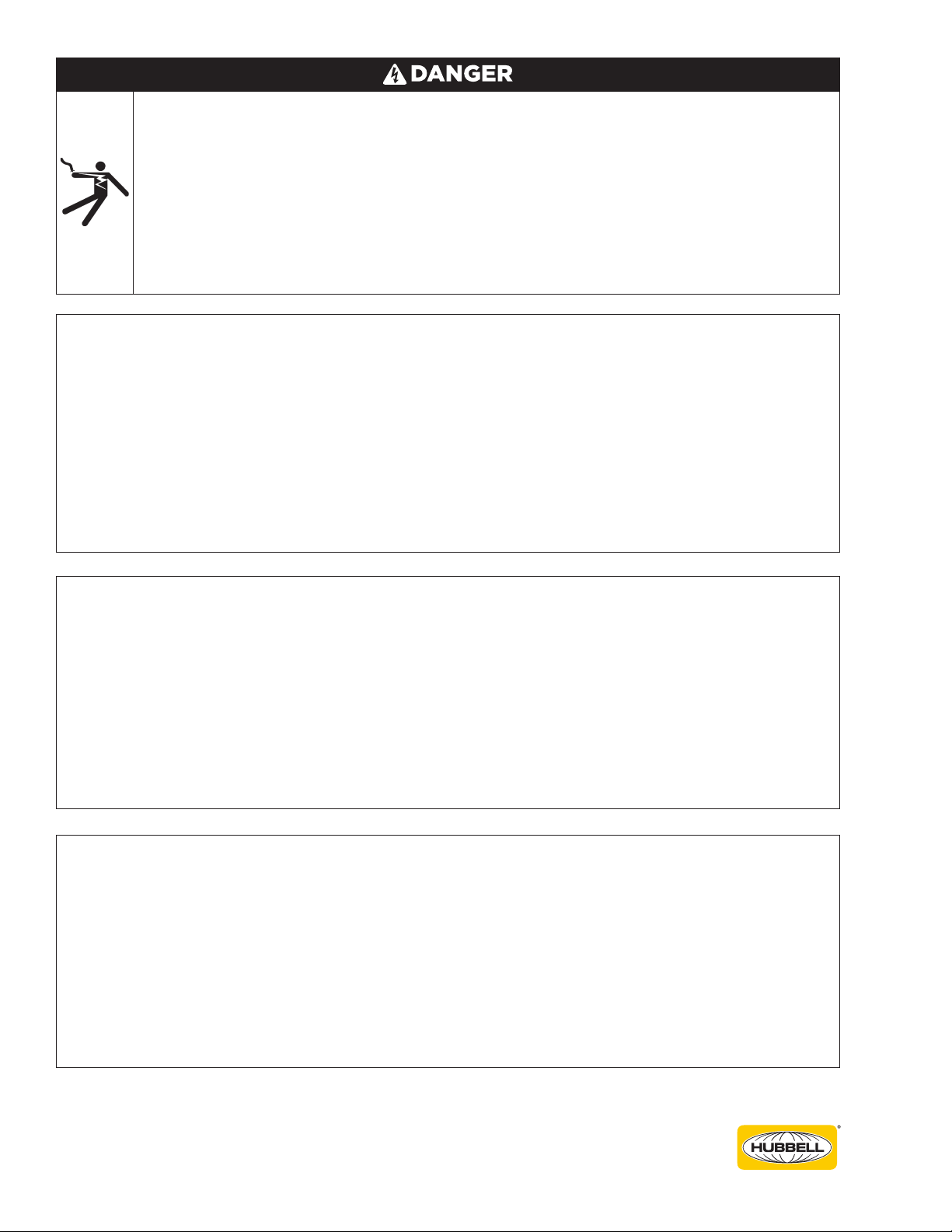
All parts of recloser are energized.
Contact with components will cause
severe personal injury, death, or
property damage.
Only qualified personnel should work
on or around this equipment after
becoming thoroughly familiar with
this document and other publications
regarding this equipment.
This equipment is not intended to protect
human life.
Can cause death, severe personal injury, and/or
equipment damage.
Follow all locally approved procedures and
safety practices when installing or operating
this equipment.
Do not place the recloser in service until all
settings have been programmed and verified.
Failure to comply can result in recloser
misoperation, equipment damage, and personal
injury.
Refer to sections 5 and 6 of this manual for
control programming and operation.
Handle position does not indicate
de-energized recloser enclosure
controls or circuit.
Contact with these components will
cause severe personal injury, death,
or property damage.
Before contacting or servicing
the equipment, or working on the
electrical system, isolate and ground
the recloser from the electrical
system. Verify recloser is de-
energized by testing with properly
rated hot sticks and/or rubber gloves
and voltmeter.
Safety Information