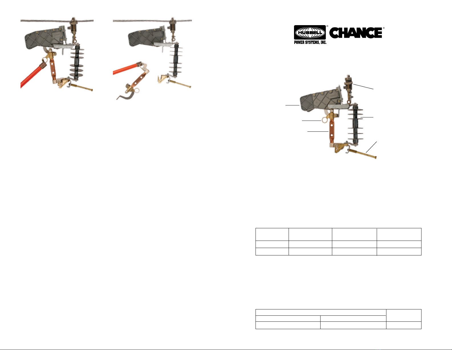
manuals.online logo
Brands
  1. Home
  2. •
  3. Brands
  4. •
  5. Hubbell
  6. •
  7. Industrial Equipment
  8. •
  9. Hubbell Chance PSC6010348 User manual

Hubbell Chance PSC6010348 User manual

FIGURE 4 FIGURE 5
NOTE: Because Hubbell has a policy of continuous product improvement, we reserve the right to
change design and specications without notice.
Both Models
Minimum
#6 solid copper (0.162")
Tap
Stud
1/2" diameter
Maximum
954 kcmil ACSR (1.20")
Main Line Range
Max. Momentary
Rating (Amps)
12,000†Asym
12,000†Asym
Epoxiglas®
Insulation Length
63/4" length
101/8" length
Max. Loadbreak
Current
300 Amps
300 Amps
System
Class
8.3/15kV*
15/27kV*
Ratings and Specifications
This unfused tool provides a temporary means of connecting and disconnecting
equipment or circuits under load conditions. This tool does not provide fault
or overcurrent protection. It has no fuse. It should never be closed into a fault
or opened during a fault. Unfused or unswitched loads can be disconnected by
first installing this tool with a temporary bypass jumper in parallel with the
permanent tap connection. After closing the blade of the tool, the permanent tap
can be disconnected. The load can then be dropped or reconnected by operating
the blade of the tool.
Load-Break
Arc Chute
Pulling Eye Insulator
Tap Stud for
Temporary Jumper
Line Conductor Clamp
* For application on single-phase-to-neutral or three-phase solidly-grounded-
wye connected circuits where recovery voltage does not exceed the maximum
design voltage of the device.
†This is a pass-through fault current rating only.
The tool should never be opened or closed when the current exceeds the
maximum continuous load current of 300 amps.
P6002400
Rev. A
Removal
To remove the Temporary Load Disconnect Tool, while maintaining a continuous
circuit connection, first make up a permanent connection or replace the previ-
ously removed permanent connection, in parallel with the tool. Now there are
two energizing paths.
This tool is equipped with an arc-chute type interrupter. The arc chute enables
the tool to perform as a loadbreak device capable of interrupting load currents.
To operate this loadbreak device, place a disconnect stick in the pull ring on the
blade (see Figure 4). Position yourself approximately 2 feet to one side of the
tool. Look away from the tool and pull sharply on the disconnect stick without
hesitation.After opening blade, swing it into a full open position. Use a disconnect
stick to remove the blade from the lower hinge (see Figure 5). With a Grip-All
clampstick remove the temporary jumper from the energized conductor and
secure it on the stud at the lower hinge. With a Grip-All clampstick remove the
tool from the energized line conductor (see Figure 1).
Checklist
1. Check tool for proper closing and latching before each use.
2. This product should not be installed for extended periods. With the blade
removed, the insulator may permit excessive leakage depending upon sur-
face contamination and the extent of surface wetting. Wiping the insulator
with a clean Chance Wiping Cloth (Cat. No. M1904) or a silicone material
will help resist this condition.
3. To assure proper closing and opening operations, always close the blade in
line with the insulator.
4. When attaching jumper clamp to load, do not pull tool out of vertical posi-
tion.
5. Inspect contacts for excessive pitting or burning and replace as necessary.
Check blade for burrs or excessive erosion and replace if necessary. Check
arc chute for cracks and replace if broken.
6. When not in use or when in storage, always keep tool in the storage case
provided.
7. After approximately 50 operations, inspect the entire tool as described in
Item 5 above.
Catalog No. Application
PSC6010347 8.3/15kV
PSC6010348 15/27kV
Temporary Load Disconnect Tool
OPERATING INSTRUCTIONS FOR
©Copyright 2007 Hubbell Power Systems, Inc. Printed in USA
P6002400
Rev. A
Blade
Hot gases and particles are expelled from the arc chute during opening.These can
cause personal injury. Look away and position yourself to the side of the arc chute
when opening.
Remove blade from the tempo-
rary load disconnect tool.
Do not proceed with blade in
the temporary load discon-
nect tool.
Do not exceed load current
rating of 300 amps.
Installation Positioning yourself approximately 2 feet to one side of the tool, place the discon-
nect stick in the pulling eye and rotate the blade to an intermediate position as
shown in Figure 3. Look away from the tool. Quickly and firmly drive the blade
into the closed position. Remove the disconnect stick from the pulling eye care-
fully to avoid opening the blade.
The equipment or circuit is now energized through the temporary load discon-
nect tool. See following instructions for removing the temporary load disconnect
tool.
FIGURE 3FIGURE 2
FIGURE 1
▲
▲
▲
▲
Blade Removed
Grip-All
Clampstick
The equipment covered by this instruction guide should be selected, installed and
serviced by competent personnel who understand proper safety procedures.This
instruction guide is written for such personnel and is not a substitute for adequate
training and experience in safety procedures regarding this type of equipment.This
guide does not claim to cover all details or variations in equipment nor to provide
for all possible conditions to be met with concerning installation,operation or main-
tenance of this equipment. If further information is desired or if particular problems
are encountered which are not sufficiently covered in this guide, contact Chance.
The equipment covered here is for temporary use only; it is not to be used perma-
nently in place of a cutout or a switch.
Do not close or open this tool on a faulted circuit.
Proper size and rating of the temporary load disconnect tool must be selected for
each installation. Should there be any concern regarding use of this tool as rated,
consult your supervisor before installation.
Only qualified personnel should operate a temporary load disconnect tool. Those
personnel must wear appropriate protective equipment such as rubber gloves,
hard hats, safety glasses, etc. in accordance with established utility and safety
practices.
Securely attach both clamps of a suitable temporary jumper onto the tap stud
on the lower hinge.
With the blade removed, use a Grip-All clampstick to install the tool securely
on the energized line conductor (see (Figure 1). Mount the assembly vertically
and allow for clearance above and below the tool to adjacent phase conductors
and grounds.
Again using a Grip-All clampstick, place one of the jumper clamps on the load
to be picked up (such as apparatus jumper or branch line). When attaching
jumper to load, do not pull tool out of vertical position.
With a disconnect stick place the blade in the lower hinge of the tool (see Figure
2).
▲
!WARNING
!WARNING
!WARNING
!CAUTION
!CAUTION
▲
!WARNING

This manual suits for next models

1

Other Hubbell Industrial Equipment manuals

Hubbell Killark ENY Series Instruction Manual

Hubbell

Hubbell Killark ENY Series Instruction Manual

Hubbell DUAL LITE SPectron User manual

Hubbell

Hubbell DUAL LITE SPectron User manual

Hubbell Killark UGFI Series Instruction Manual

Hubbell

Hubbell Killark UGFI Series Instruction Manual

Hubbell RAFB4 Series User manual

Hubbell

Hubbell RAFB4 Series User manual

Hubbell GFP20FWM User manual

Hubbell

Hubbell GFP20FWM User manual

Hubbell HBL6750TFIV User manual

Hubbell

Hubbell HBL6750TFIV User manual

Hubbell VERSA-TECH I User manual

Hubbell

Hubbell VERSA-TECH I User manual

Hubbell Walltrak PW2FEBC User manual

Hubbell

Hubbell Walltrak PW2FEBC User manual

Hubbell KILLARK EYS Instruction Manual

Hubbell

Hubbell KILLARK EYS Instruction Manual

Hubbell TredTrak User manual

Hubbell

Hubbell TredTrak User manual

Hubbell KILLARK UGFI 2P Series Instruction Manual

Hubbell

Hubbell KILLARK UGFI 2P Series Instruction Manual

Hubbell CHANCE PSC3090323CE User manual

Hubbell

Hubbell CHANCE PSC3090323CE User manual

Hubbell CFBS1R8CVR User manual

Hubbell

Hubbell CFBS1R8CVR User manual

Hubbell GAI-TRONICS 234 User manual

Hubbell

Hubbell GAI-TRONICS 234 User manual

Hubbell CFB2G25R User manual

Hubbell

Hubbell CFB2G25R User manual

Hubbell HBL985 User manual

Hubbell

Hubbell HBL985 User manual

Hubbell PSC2080579 User manual

Hubbell

Hubbell PSC2080579 User manual

Popular Industrial Equipment manuals by other brands

Greenlee FS439-100 instruction manual

Greenlee

Greenlee FS439-100 instruction manual

Carlisle Fluid Technologies IntelliSpray IS40 user manual

Carlisle Fluid Technologies

Carlisle Fluid Technologies IntelliSpray IS40 user manual

Eaton SVC-T3 Instruction leaflet

Eaton

Eaton SVC-T3 Instruction leaflet

Siemens RUGGEDCOM WIN5151-V-GPS installation guide

Siemens

Siemens RUGGEDCOM WIN5151-V-GPS installation guide

ETI NETCOM ADH instruction manual

ETI

ETI NETCOM ADH instruction manual

Cumberland EDGE 890-00601 Installation and user manual

Cumberland

Cumberland EDGE 890-00601 Installation and user manual

Kooltronic KPHE32 Series Operator's manual

Kooltronic

Kooltronic KPHE32 Series Operator's manual

Formax FD 280-20 Operator's manual

Formax

Formax FD 280-20 Operator's manual

PISCO VK Series manual

PISCO

PISCO VK Series manual

Tormach PCNC 770 Assembly manual

Tormach

Tormach PCNC 770 Assembly manual

GSi 40 Series Construction manual

GSi

GSi 40 Series Construction manual

Seneca USB-ISO installation manual

Seneca

Seneca USB-ISO installation manual

Maxcess Tidland Advantage Series user manual

Maxcess

Maxcess Tidland Advantage Series user manual

Hiwin XEG Series user manual

Hiwin

Hiwin XEG Series user manual

M-system M8BS-16U5 instruction manual

M-system

M-system M8BS-16U5 instruction manual

Idex BAND-IT S75099 Owner Manual and Tool Operating Instructions

Idex

Idex BAND-IT S75099 Owner Manual and Tool Operating Instructions

ABB HT611636 Operation manual

ABB

ABB HT611636 Operation manual

Graco 239802 Instructions-parts list

Graco

Graco 239802 Instructions-parts list

manuals.online logo
manuals.online logoBrands
  • About & Mission
  • Contact us
  • Privacy Policy
  • Terms and Conditions

Copyright 2025 Manuals.Online. All Rights Reserved.