Huck 2025 User manual

May 26, 2015
HK1006
Makers of Huck®, Marson®, Recoil®
Brand Fasteners, Tools & Accessories
InstructIon Manual
2025 serIes
PneudraulIc InstallatIon tools
Standard 2025 shown with Nose Assembly (not included)

2
2025 Series Pneudraulic Installation Tools (HK1006)Alcoa Fastening Systems & Rings

3
2025 Series Pneudraulic Installation Tools (HK1006)Alcoa Fastening Systems & Rings
Contents
ec declaratIon of conforMIty .........................2
contents ..........................................3
safety InstructIons ..................................4
sPecIfIcatIons.....................................5–7
PrIncIPle of oPeratIon ................................8
PreParatIon for use .................................8
oPeratIng InstructIons ...............................9
MaIntenance
General ......................................9
Daily .........................................9
Weekly .......................................9
dIsasseMbly
General .....................................10
HeaD/HanDle .................................11
Pintail Bottle/Vacuum SyStem ....................11
asseMbly
HeaD/HanDle .................................12
General .....................................13
Pintail Bottle/Vacuum SyStem ....................13
fIll and bleed .....................................14
MeasurIng tool stroke ..............................15
asseMbly drawIngs .............................16 & 17
Parts lIst ....................................18 & 19
troubleshootIng ...................................20
accessorIes .......................................20

4
2025 Series Pneudraulic Installation Tools (HK1006)Alcoa Fastening Systems & Rings
I. GENERAL SAFETY RULES:
1. A half hour long hands-on training session with qualied personnel is
recommendedbeforeusingHuckequipment.
2. Huckequipmentmustbemaintainedinasafeworkingconditionatalltimes.
Tools and hoses should be inspected at the beginning of each shift/day for
damageorwear.Anyrepairshouldbedonebyaqualiedrepairmantrainedon
Huckprocedures.
3. For multiple hazards, read and understand the safety instructions before
installing, operating, repairing, maintaining, changing accessories on, or
workingneartheassemblypowertool.Failuretodosocanresultinserious
bodilyinjury.
4. Onlyqualiedandtrainedoperatorsshouldinstall,adjustorusetheassembly
powertool.
5. Do not modify this assembly power tool. This can reduce effectiveness of
safetymeasuresandincreaseoperatorrisk.
6. Donotdiscardsafetyinstructions;givethemtotheoperator.
7. Donotuseassemblypowertoolifithasbeendamaged.
8. Toolsshallbeinspectedperiodicallytoverifyallratingsandmarkingsrequired,
andlistedinthemanual,arelegiblymarkedonthetool.Theemployer/operator
shall contact the manufacturer to obtain replacement marking labels when
necessary.Refertoassemblydrawingandpartslistforreplacement.
9. Toolisonlytobeusedasstatedinthismanual.Anyotheruseisprohibited.
10.ReadMSDSSpecicationsbeforeservicingthetool.MSDSspecicationsare
availablefromtheproductmanufactureroryourHuckrepresentative.
11.OnlygenuineHuckpartsshallbeusedforreplacementsorspares.Useofany
otherpartscanresultintoolingdamageorpersonalinjury.
12.Neverremoveanysafetyguardsorpintaildeectors.
13.Neverinstallafastenerinfreeair.Personalinjuryfromfastenerejectingmay
occur.
14.Where applicable, always clear spent pintail out of nose assembly before
installing the next fastener.
15.Checkclearancebetween trigger and work piece to ensure thereis no pinch
pointwhentoolisactivated.Remotetriggersareavailableforhydraulictooling
ifpinchpointisunavoidable.
16.Donotabusetoolbydroppingorusingitasahammer.Neverusehydraulicor
airlinesasahandleortobendorprythetool.Reasonablecareofinstallation
tools by operators is an important factor in maintaining tool efciency,
eliminating downtime, and preventing an accident which may cause severe
personalinjury.
17.Neverplacehandsbetweennoseassemblyandworkpiece.Keephandsclear
from front of tool.
18.Tools with ejector rods should never be cycled with out nose assembly
installed.
19.When two piece lock bolts are being used always make sure the collar
orientationiscorrect.Seefastenerdatasheetforcorrectpositioning.
II. PROJECTILE HAZARDS:
1. Riskofwhippingcompressedairhoseiftoolispneudraulicorpneumatic.
2. Disconnect the assembly power tool from energy source when changing
inserted tools or accessories.
3. Beawarethatfailureoftheworkpiece,accessories, ortheinsertedtoolitself
cangeneratehighvelocityprojectiles.
4. Alwayswearimpactresistanteyeprotectionduringtooloperation.Thegrade
ofprotectionrequiredshouldbeassessedforeachuse.
5. The risk of others should also be assessed at this time.
6. Ensurethattheworkpieceissecurelyxed.
7. Check that the means of protection from ejection of fastener or pintail is in
placeandoperative.
8. Thereispossibilityofforcibleejectionofpintailsorspentmandrelsfromfront
of tool.
III. OPERATING HAZARDS:
1. Use of tool can expose the operator’s hands to hazards including: crushing,
impacts,cuts,abrasionsandheat.Wearsuitableglovestoprotecthands.
2. Operators and maintenance personnel shall be physically able to handle the
bulk,weightandpowerofthetool.
3. Holdthetoolcorrectlyandbereadytocounteractnormalorsuddenmovements
withbothhandsavailable.
4. Maintainabalancedbodypositionandsecurefooting.
5. Releasetriggerorstopstartdeviceincaseofinterruptionofenergysupply.
6. Useonlyuidsandlubricantsrecommendedbythemanufacturer.
7. Avoidunsuitablepostures,asitislikelyforthesenottoallowcounteractingof
normalorunexpectedtoolmovement.
8. If the assembly power tool is xed to a suspension device, make sure that
xationissecure.
9. Bewareoftheriskofcrushingorpinchingifnoseequipmentisnottted.
IV. REPETITIVE MOTION HAZARDS:
1. Whenusingassemblypowertool,theoperatorcanexperiencediscomfortinthe
hands,arms,shoulders,neckorotherpartsofthebody.
2. When using tool, the operator should adopt a comfortable posture while
maintainingasecurefootingandavoidawkwardoroffbalancedpostures.
3. The operator should change posture during extended tasks to help avoid
discomfort and fatigue.
4. Iftheoperatorexperiencessymptomssuchaspersistentorrecurringdiscomfort,
pain, throbbing, aching, tingling, numbness, burning sensations or stiffness,
thesewarningsshould not be ignored. The operator should tell the employer
andconsultaqualiedhealthprofessional.
V. ACCESSORIES HAZARDS:
1. Disconnecttoolfromenergysupplybeforechanginginsertedtooloraccessory.
2. Useonlysizesandtypesofaccessoriesandconsumablesthatarerecommended.
Donotuseothertypesorsizesofaccessoriesorconsumables.
VI. WORKPLACE HAZARDS:
1. Be aware of slippery surfaces caused by use of the tool and of trip hazards
causedbytheairlineorhydraulichose.
2. Proceedwithcautionwhileinunfamiliarsurroundings;therecouldbehidden
hazardssuchaselectricityorotherutilitylines.
3. The assembly power tool is not intended for use in potentially explosive
environments.
4. Toolisnotinsulatedagainstcontactwithelectricalpower.
5. Ensuretherearenoelectricalcables,gaspipes,etc.,whichcancauseahazard
ifdamagedbyuseofthetool.
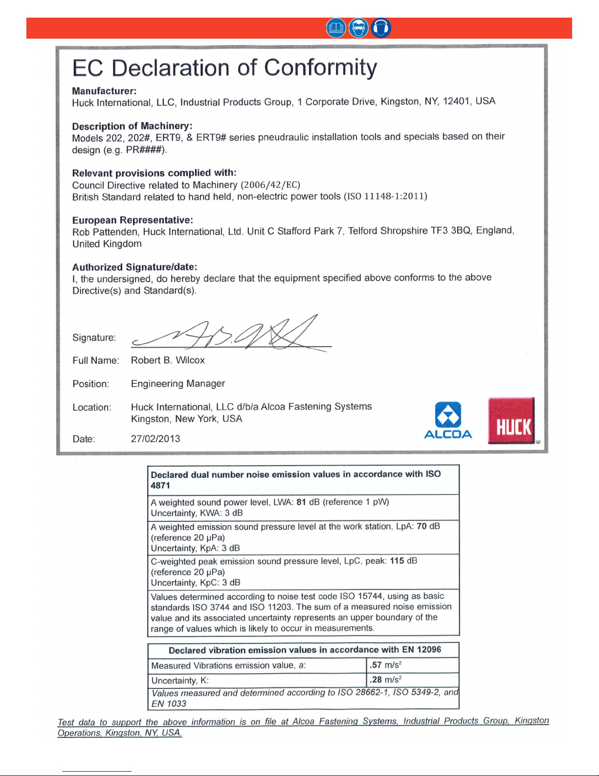
VII. NOISE HAZARDS:
1. Exposure to high noise levels can cause permanent, disabling hearing loss
and other problems such as tinnitus, therefore risk assessment and the
implementationofpropercontrolsisessential.
2. Appropriatecontrolstoreducetherisk mayincludeactionssuchasdamping
materialstopreventworkpiecefrom‘ringing’.
3. Use hearing protection in accordance with employer’s instructions and as
requiredbyoccupationalhealthandsafetyregulations.
4. Operate and maintain tool as recommended in the instruction handbook to
preventanunnecessaryincreaseinthenoiselevel.
5. Select,maintainandreplacetheconsumable/insertedtoolasrecommendedto
preventanunnecessaryincreaseinnoise.
6. Ifthepower toolhasasilencer,alwaysensurethatitisinplaceandingood
workingorderwhenthetoolisbeingoperated.
VIII. VIBRATION HAZARDS:
1. Exposure to vibration can cause disabling damage to the nerves and blood
supplytothehandsandarms.
2. Wearwarmclothingwhen workingincoldconditionsandkeephands warm
anddry.
3. Ifnumbness,tingling,painorwhiteningoftheskininthengersorhands,stop
usingthetool,tellyouremployerandconsultaphysician.
4. Supporttheweightofthetoolinastand,tensionerorbalancerinordertohave
alightergriponthetool.
IX. PNEUMATIC / PNEUDRAULIC TOOL SAFETY INSTRUCTIONS:
1. Airunderpressurecancausesevereinjury.
2. Always shut off air supply, drain hose of air pressure and disconnect tool
fromairsupplywhennotinuse,beforechangingaccessoriesorwhenmaking
repairs.
3. Neverdirectairatyourselforanyoneelse.
4. Whippinghosescancause severeinjury,alwayscheckfor damagedorloose
hosesandttings.
5. Coldairshouldbedirectedawayfromhands.
6. Wheneveruniversaltwistcouplings(clawcouplings)areused,lockpinsshall
be installed and whipcheck safety cables shall be used to safeguard against
possiblehosetohoseorhosetotoolconnectionfailure.
7. Donotexceedmaximumairpressurestatedontool.
8. Nevercarryanairtoolbythehose.
safety InstruCtIons
GLOSSARY OF TERMS AND SYMBOLS:
- Product complies with requirements set forth by the
relevant European directives.
- READ MANUAL prior to using this equipment.
- EYE PROTECTION IS REQUIRED while using this
equipment.
- HEARING PROTECTION IS REQUIRED while using this
equipment.
Notes: are reminders of required procedures.
Bold, Italic type and underlining: emphasizes a specic instruction.
WARNINGS: Must be understood to avoid
severe personal injury.
CAUTIONS: show conditions that will
damage equipment and or structure.

5
2025 Series Pneudraulic Installation Tools (HK1006)Alcoa Fastening Systems & Rings
speCIfICatIons
STROKE: 0.675 in. (1.715 cm)
WEIGHT:
2025 & 2025L: 5 lbs 12oz (2.608 kg)
2025S & 2025SL: 7 lbs 4 ozs. (3.289 kg)
MAX AIR PRESSURE: 90 psi (6.2 BAR)
MAX FLOW RATE: 8.5 scfm (241 l/m)
POWER SOURCE: 90 psi (6.2 BAR) MAX
shop air
MAX OPERATING TEMP: 125° F (51.7° C)
PULL CAPACITY:
5290 lbs @ 90 psi (23.531 kN @ 6.2 BAR)
SPEED / CYCLES: 30 per minute
HOSE KITS: Use only genuine HUCK
Hose Kits rated @ 10,000 (689.5 BAR) psi
working pressure.
HYDRAULIC FLUID:
Hydraulic uid shall meet DEXRON III,
DEXRON VI, MERCON, Allison C-4
or equivalent ATF specications. Fire-
resistant uid may be used if it is an ester-
based uid such as Quintolubric HFD or
equivalent. Water-based uid shall NOT be
used as serious damage to equipment will
occur.
Models
2025, 2025L,
2025S &2025SL

6
2025 Series Pneudraulic Installation Tools (HK1006)Alcoa Fastening Systems & Rings
Models
2025V &2025LV
speCIfICatIons
STROKE: 0.675 in. (1.715 cm)
WEIGHT: 5 lbs 12oz (2.608 kg)
MAX AIR PRESSURE: 90 psi (6.2 BAR)
MAX FLOW RATE: 8.5 scfm (241 l/m)
POWER SOURCE: 90 psi (6.2 BAR) MAX
shop air
MAX OPERATING TEMP: 125° F (51.7° C)
PULL CAPACITY:
5290 lbs @ 90 psi (23.531 kN @ 6.2 BAR)
SPEED / CYCLES: 30 per minute
HOSE KITS: Use only genuine HUCK
Hose Kits rated @ 10,000 (689.5 BAR) psi
working pressure.
HYDRAULIC FLUID:
Hydraulic uid shall meet DEXRON III,
DEXRON VI, MERCON, Allison C-4
or equivalent ATF specications. Fire-
resistant uid may be used if it is an ester-
based uid such as Quintolubric HFD or
equivalent. Water-based uid shall NOT be
used as serious damage to equipment will
occur.

7
2025 Series Pneudraulic Installation Tools (HK1006)Alcoa Fastening Systems & Rings
Models
2025B &2025LB
STROKE: 0.675 in. (1.715 cm)
WEIGHT: 5 lbs 12oz (2.608 kg)
MAX AIR PRESSURE: 90 psi (6.2 BAR)
MAX FLOW RATE: 8.5 scfm (241 l/m)
POWER SOURCE: 90 psi (6.2 BAR) MAX
shop air
MAX OPERATING TEMP: 125° F (51.7° C)
PULL CAPACITY:
5290 lbs @ 90 psi (23.531 kN @ 6.2 BAR)
SPEED / CYCLES: 30 per minute
HOSE KITS: Use only genuine HUCK
Hose Kits rated @ 10,000 (689.5 BAR) psi
working pressure.
HYDRAULIC FLUID:
Hydraulic uid shall meet DEXRON III,
DEXRON VI, MERCON, Allison C-4
or equivalent ATF specications. Fire-
resistant uid may be used if it is an ester-
based uid such as Quintolubric HFD or
equivalent. Water-based uid shall NOT be
used as serious damage to equipment will
occur.
speCIfICatIons

8
2025 Series Pneudraulic Installation Tools (HK1006)Alcoa Fastening Systems & Rings
The 2025 series of tools ship with a plug in the air inlet
connector. The connector has 1/4-18 female pipe threads
to accept the air hose tting. Huck recommends quick-
disconnect ttings and a 1/4” inside-diameter air hose.
The air supply should be equipped with a lter-regulator-
lubricator unit, and access to a 90 psi (6.2 BAR) air
supply capable of 20 ft³/s (.57 m³/s).
NOTE: Air quick-disconnect ttings and air hoses are not
available from Huck International, Inc.
1. Remove the shipping plug from air inlet connector
and add a few drops of an approved hydraulic uid.
2. Screw the quick-disconnect tting into the air inlet
connector.
3. Set the air pressure on the regulator to 90–100 psi,
and connect the air hose to the tool.
4. Press and release the trigger a few times to cycle
the tool. Disconnect the air hose from the tool, and
remove the retaining nut.
5. Select the proper nose assembly for the fastener
being installed.
6. Screw the collet assembly (including the lock collar
and shim if applicable) onto the spindle and tighten
with a wrench.
7. Slide the anvil over the collet assembly and into the
counterbore. Slide the retaining nut over the anvil,
and screw the nut onto the head.
8. Connect the air hose to the tool and install fasteners
in a test plate of proper thickness with proper size
holes. Inspect the fasteners.
If fasteners do not pass inspection, see
troubleshootIng to investigate possible causes.
NOTE: On older nose assemblies with lock collars, use
Loctite®243™ on collet threads, because the 2025 pull
piston does not have staking holes. Refer to the nose
assembly drawings that shipped with nose assemblies.
Teon is a registered trademark of du Pont de Nemours and Company.
Threadmate is a registered trademark of Parker Intangibles, LLC.
Loctite is a registered trademark of Henkel Corporation, U.S.A.
preparatIon for use
CAUTION: Do not use Teon®tape on
pipe threads. Tape can shred, resulting in
malfunctions. Threadmate®is available in a
4oz. tube from Huck (P/N 508517).
When the trigger is pressed, the throttle valve moves
downward to the PULL position, and pressurized air
is directed to the bottom of the air piston, causing it to
move upward (Figure 1A). The air above the air piston is
exhausted and directed through the center of the throttle
valve and out the bottom of the tool.
As the hydraulic rod moves upward, a column of uid is
forced into head, which moves the pull piston backward.
The attached nose assembly moves with the pull piston
to start fastener installation.
When fastener installation is completed, the trigger is
released. Air pressure, with the assistance of a spring,
sends the throttle valve to the up (RETURN) position.
Pressurized air is re-directed to the top of the air piston
(Figure 1B), causing the air piston and hydraulic rod to
move downward.
The air from below the piston is exhausted through the
bottom of the tool, and springs force the pull piston to
return to its home position. The damper valve (Figure 1A)
impedes oil ow at pinbreak to prevent “tool kick.”
fIgure 1afIgure 1b
prInCIples of operatIon

9
2025 Series Pneudraulic Installation Tools (HK1006)Alcoa Fastening Systems & Rings
GENERAL
The operating efciency of your tool is directly related to
the performance of the entire system. Regular inspection
and the immediate correction of minor problems will keep
the tool operating efciently, and prevent downtime. A
schedule of “preventive” maintenance of the tool, nose
assembly, hoses, trigger and control cord, and POWERIG
will ensure your tool’s proper operation and extend its life.
NOTE: Huck tools should be serviced only by personnel
who are thoroughly familiar with its operation.
√Service the tool in a clean, well-lighted area. Take
special care to prevent contamination of pneumatic
and hydraulic systems.
√Have available all necessary hand tools—standard
and special.
√Carefully handle all parts. Before reassembly,
examine them for damage and wear. Always replace
seals when a tool is disassembled.
√ Disassemble and assemble tool components in a
straight line. Do NOT bend, cock, twist, or apply
undue force. Follow the dIsasseMbly and asseMbly
procedures in this manual.
√Have Service Parts Kit 2025KIT available when
servicing the tool; it includes important consumable
parts. Other components, as experience dictates,
should also be available.
For supplementary information, refer to troubleshootIng,
Parts lIsts, and the dIsasseMbly and asseMbly
procedures in this manual.
DAILY
√ If a Filter-Regulator-Lubricator unit is not being used,
uncouple the air disconnects and add a few drops of
hydraulic uid or a light-weight oil to the air inlet of
the tool.
NOTE: If the tool is in continuous use, add a few
drops of oil in every 2–3 hours.
√Before connecting an air hose to the tool, bleed the
air lines to clear dirt or water.
√Check all hoses and couplings for damage and air
leaks; tighten or replace if necessary.
√Check the tool for damage and air or hydraulic leaks;
tighten, repair, or replace if necessary.
√Check the nose assembly for tightness and damage;
tighten or replace if necessary.
√ Periodically, check the tool stroke. If the stroke is
short, add uid. For more information, see MeasurIng
tool stroke on page 15.
WEEKLY
√ Disassemble, clean, and reassemble nose assembly
in accordance with applicable instructions.
√Check the tool and all connecting parts for damage
and uid/air leaks; tighten or replace if necessary.
MaIntenanCe
operatIng InstruCtIons
WARNINGS:
Inspect tools for damage and wear before
using. Do not use if damaged or worn;
serious personal injury may occur.
Pulling a pin without a collar, or with collar
chamfer against workpiece, may result in
the pin becoming a high-speed projectile
when the pin grooves are stripped or the
pintail breaks off. Serious personal injury
may occur to anyone in the pin’s “ight
path.” This includes pins that ricochet.
Broken pintails eject from the deector with
speed and force. Be sure the pintail deector
is directed safely away from all personnel.
Ejecting pintails striking anyone may cause
serious personal injury. Always use pintail
bottles with models 2025B and 2025V.
Replace damaged pintail deectors and
bottles to avoid serious personal injury.
BLIND FASTENER INSTALLATION
The fastener can be placed in either the work hole or
the end of the nose assembly. For both methods, the
tool and nose assembly must be held against the work
and at a right angle (90-degrees) to it. Press and hold
the trigger until the fastener is installed and the pintail
breaks. Release the trigger.
MAGNA-GRIP®FASTENER INSTALLATION
Place the pin in the work-hole and place the collar over
the pin. See WARNINGS. (If the collar has only one
tapered end, that end must be out toward tool.) Hold
the pin in the hole. Push the nose assembly onto the
pin protruding from the collar until the anvil touches
the collar. Press and hold the trigger until the collar is
swaged and the pintail breaks. Release the trigger.
CAUTION: Remove excess gap from
between sheets so that enough of the pintail
protrudes from the collar that all of the jaw
teeth can grip the pintail grooves. Jaws that
are not fully gripping pintail grooves will be
stripped or broken.

10
2025 Series Pneudraulic Installation Tools (HK1006)Alcoa Fastening Systems & Rings
DIsasseMbly
WARNING: Disconnect the air hose from the
tool before performing any maintenance.
Serious personal injury could result if the air
hose is connected.
This procedure is for complete disassembly of the tool.
Disassemble only those components necessary to replace
damaged O-rings, Quad-rings, Back-up rings, and worn or
damaged components. For component identication, see
Figures 2, 14, & 15.
CAUTION: Always use a soft-jaw vise to avoid
damaging the tool.
general
NOTE: For models 2025S & 2025SL, follow the
procedures for models 2025 & 2025L.
1. Disconnect the tool from the air source.
2. Unscrew the retaining nut (7), and remove the nose
assembly.
3. Unscrew the bleed plug (55) from top of the handle/
head. Turn over the tool and drain the uid into a
container. (Figures 10 & 14)
4. Models 2025 & 2025L: Pull the pintail deector (24)
off the end cap (21).
Models 2025B & 2025LB: Reach in the window of the
pintail bottle (24) and remove the retaining ring (62)
and washer (63); then remove the pintail bottle (24)
and adapter (64). (Figures 14 & 15)
Models 2025V & 2025LV: See PIntaIl bottle/VacuuM
systeM on page 11.
5. Remove the throttle arm pivot screw (48) and the
lever guard (73). Lift out the throttle arm (53), and
disconnect ball end of the cable assembly (2) from it.
6. Secure the tool in a vise, upside-down. (Figure 2)
Remove the button head screws (40) with 1/8” hex
key. Remove the end cap (41) and gasket (39), and
remove the mufer (42) from the end cap. Remove
the spring (49) from the throttle valve. (Figure 14)
7. Tap down the cylinder head (45) with a soft mallet (to
take pressure off the ring), and remove the retaining
ring (38). (Figure 2)
8. Screw the button head screws (40) into the cylinder
head, and carefully pry on the screws to remove the
head. Remove the O-ring (46).
9. Pull on lock nut (43) with vise-grips to remove air
piston from cylinder. Remove piston Quad-ring (47).
CAUTION: Take care to not scratch the piston
rod or cylinder when removing.
10. Remove the bumper (34) from the gland assembly.
Unscrew gland assembly (25) with 1-3/8” socket
wrench and extension.
11. Remove the Spirolox®Retaining Ring (30) from the
gland (26), and then pull out the spacer (29) and
Polyseal (28). Remove the O-rings (31 & 27), Quad-
ring (33), and Back-up ring (32). (Figure 14)
12. Lift the cylinder (35) from the handle/head (1).
13. Turn over the tool (1) and drain the uid into a
container; discard the uid.
14. Remove the throttle valve (52) from the air cylinder
(35), and remove the O-rings (50). (Figure 14)
Spirolox is a registered trademark of Smalley Steel Ring Company
fIgure 2

11
2025 Series Pneudraulic Installation Tools (HK1006)Alcoa Fastening Systems & Rings
head/handle
This procedure is applicable to models 2025 and 2025L.
For component identication, see Figures 3, 4, & 14.
NOTE: For 2025V, see PIntaIl bottle/VacuuM systeM on
page 11.
1. Unscrew end cap (21); remove spring (19), spacer
(22), and wiper seal (23).
2. Thread the Polyseal Insertion Tool into the rear of the
handle/head. (Figure 3)
3. Slide the spacer (P/N 123112-2 [2025] / 123112-3
[2025L]) onto the piston. Thread the Piston Assembly
Tool (P/N 123111-2 [2025] / 123111-4 [2025L]) onto
the piston.
4. Push the piston and front gland assemblies out the
back of the handle/head (1). Allow clearance, with
stand-off, as the piston leaves the tool. (Figure 4)
5. Un-thread the Piston Assembly Tool and remove
Spacer from the piston. Re-thread the Piston
Assembly Tool onto the piston, then slide the front
gland assembly off the piston (6). (Figure 4)
6. Remove the Piston Assembly Tool from the piston (6),
and remove the Polyseal Insertion Tool from the rear
of the head/handle (1).
7. Remove the retaining ring (16), washer (17), and
Polyseal (18) from the piston.
NOTE: Inspect the hydraulic piston for wear, scoring,
and damage; replace if necessary.
8. Unscrew the adapter (8). (Figure 14) Inspect all seals
and parts.
9. If trigger cable assembly (2) is damaged, remove it by
driving the pin (4) out with punch. Remove dowel pin
(3) to disconnect cable from trigger.
PIntaIl bottle/VacuuM systeM
This procedure is applicable to models 2025V and
2025LV only; it should be used in conjunction with
the previous sections, general and head/handle. For
component identication, see Figures 5, 6, & 15.
1. Reach through the window of pintail bottle (24) and
remove the retaining ring (62) and washer (63).
(Figure 5)
2. Remove the pintail bottle (24), and then disconnect
the tube from the connector (54). (Figure 15)
3. Remove the adapter (64) and tube/slide assy (70).
4. Remove the end cap (21) and spring (19). (Figure 6)
5. Remove the spacer (22) and O-ring (68) from the
spring side of the end cap.
6. Remove the retaining ring (66), wiper housing (67),
wiper seal (23), washer (71) and O-ring (69) from the
bottle side of the end cap.
7. Remove the O-rings (65) from inside the adapter and
tube/slide assembly (70). (Figure 15)
fIgure 4
fIgure 3
DIsasseMbly (ContInueD)
fIgure 5
fIgure 6

12
2025 Series Pneudraulic Installation Tools (HK1006)Alcoa Fastening Systems & Rings
asseMbly
head/handle
This procedure is for the assembly of the head/handle of
models 2025, 2025B, 2025L, and 2025LB. For models
2025S and 2025SL, follow the procedures for models
2025 and 2025L. For component identication, see
Figures 7, 8, & 14.
Prior to re-assembling the tool:
• Clean components with mineral spirits or a similar
solvent. Inspect for wear/damage and replace as
necessary.
• Replace all seals of disassembled components.
• Use the O-rings, Quad-rings, and Back-up rings from
Huck Service Parts Kits (P/N 2025KIT or 2025VKIT).
When assembling the tool, take care not to damage
O-rings, Quad-rings, Back-up rings.
Smear LubriPlate®130-AA (Huck P/N 502723) or
Parker O-Lube®(Huck P/N 505476) on O-rings,
Quad-rings, Back-up rings, and mating parts to ease
assembly.
To re-assemble the tool:
1. If removed, position cable assembly (2) in the trigger
(5) slot and slide dowel pin (3) through the holes in
trigger-and-cable assembly. Position the assembled
trigger in the handle and drive the pin (4) through the
holes in the handle and trigger. (Figure 14)
2. Screw nose adapter (8) into head (1) and tighten.
3. Thread the Polyseal Insertion Tool (P/N 121694-
2025) into the head.
4. Assemble the piston (6), Polyseal (18) and retaining
ring (16). (Note the orientation of the Polyseal (18) in
Figure 7.)
5. Assemble the front gland (15), O-ring (12), Back-up
ring (11), Polyseal (14), and gland pap (10). (Note
the orientation of the Polyseal (14) in Figure 7.)
6. Thread the Piston Assembly Tool (P/N 123111-2
[2025, 2025B, 2025V] / 123111-4 [2025L, 2025LB,
2025LV]) onto the piston (6). Slide the complete
gland assembly and wiper seal (9) onto piston (6).
7. Use a press to gently install the assembled
components through the rear of the tool. (Figure 8)
8. Remove the Piston Assembly Tool and Polyseal
Insertion Tool.
9. Install the rear wiper seal (23) into the end cap (21).
(Figure 14)
10. Slide spacer (22) and spring (19) into end cap (21),
and then thread end cap assembly into rear of head.
NOTE: For 2025V, see PIntaIl bottle/VacuuM systeM on
page 13.
LubriPlate is a registered trademark of Lubriplate Lubricants Company.
Parker O-Lube is a registered trademark of Parker Hannin Corp.
fIgure 8
fIgure 7

13
2025 Series Pneudraulic Installation Tools (HK1006)Alcoa Fastening Systems & Rings
asseMbly (ContInueD)
general
For component identication, see Figures 2, 7, 14, & 15.
1. Secure the head/handle (1) upside-down in a soft-
jaw vise. (Figure 2) Place the inverted cylinder
assembly (35) on the base of the handle. (The timing
pin maintains orientation.)
2. Assemble the gland assembly (25) with new seals.
(Note the orientation of the Polyseal (18) in Figure
7.) Apply Anti-Seize Compound (P/N 508183) to
the threads of the gland assembly. Screw the gland
assembly into the head/handle and torque it to 50 ft.-
lbs. using a 1-3/8” socket wrench.
3. Push bumper (34) rmly over gland.
NOTE: The side of the bumper with two slots must
face the bottom of the tool.
4. Install the Quad-ring (47) onto the air piston (37).
5. Lubricate the piston rod. Press the assembled air
piston/rod into the cylinder just enough to allow
installation of the cylinder head (45).
6. Assemble O-Ring (46) onto the cylinder head (45)
and then push the cylinder head squarely into the
cylinder, taking care not to damage O-ring (46).
Install the retaining ring (38); align the screw holes
with the mufer end cap.
7. Position the mufer (42) in center of cylinder head.
Position the gasket (39) on cylinder. (Figure 2) Note
the direction of the lip in Figure 7.
8. Carefully position the bottom plate (41) on cylinder.
Make sure that the mufer is properly positioned in
the recess of the bottom plate (41). (Figures 2 & 14)
9. Secure the bottom plate with the three button head
screws (40) using a 1/8” hex key. (Figure 2)
10. Assemble O-rings (50) on throttle valve (52). (Figure
14 Section CC)
11. Place the tool upright on a level surface. Drop the
spring (49) into the throttle valve bore in the cylinder
(35), and push the throttle valve into the cylinder.
12. Place the ball end of the throttle cable (2) into the
end of the throttle arm (53), then slide the throttle
arm into the slot on the cylinder. (Figure 14)
13. Snap the lever guard (73) in place, and install the
pivot screw (48) in the cylinder to retain the throttle
arm (53).
14. Models 2025 & 2025L: Push the pintail deector (24)
onto the end cap (21).
Models 2025B & 2025LB: Position the adapter (64)
and pintail bottle (24) on the end cap. Reach in the
window of the pintail bottle and install the retaining
ring (62) and washer (63). (Figures 14 & 15)
Models 2025V & 2025LV: See PIntaIl bottle/VacuuM
systeM on page 13.
The tool is now assembled and must be lled with
hydraulic uid prior to use. Refer to fIll and bleed on
page 14.
PIntaIl bottle/VacuuM systeM
This procedure is applicable to models 2025V and
2025LV only; it should be used in conjunction with
the previous sections, general and head/handle. For
component identication, see Figures 5, 6, & 15.
1. Assemble adapter and tube/slide assembly (70) and
new O-rings (65).
2. From bottle side of end cap (21) install O-ring (69),
washer (71), wiper seal (23), wiper housing (67) and
retaining ring (66) as shown in Figure 6.
3. From spring side of end cap install O-ring (68),
spacer (22), and spring (19). (Figure 6) Screw the
entire assembly into the head; tighten.
4. Assemble the tube/slide assembly and O-rings (65);
slide the complete assembly onto the end cap (21),
and push tube into the connector (54). (Figure15)
5. Position the adapter (64) and pintail bottle (24) on
the end cap (21). (Figures 5 & 15)
6. Reach through the window of the pintail bottle (24)
and install the washer (63) and retaining ring (62) as
shown in Figure 5.

14
2025 Series Pneudraulic Installation Tools (HK1006)Alcoa Fastening Systems & Rings
fIll anD bleeD
This section documents the “bleed-&-ll” procedure. For
component identication, see Figures 9, 10, & 11.
requIred equIPMent
• Automatic Transmission Fluid (ATF) DEXRON III or
equivalent (Refer to the sPecIfIcatIons sections for
more information.)
• Shop air-line with 90–100 psi (6.2–6.9 BAR) max.
• Air regulator
• Fill and Bleed Bottle (P/N 120337, supplied with tool)
• Large at-blade screwdriver
• Stall Nut (P/N 124090 or 125340, optional)
• Nose assembly
• Fasteners (optional)
PreParatIon
• Install air regulator
in the air-line and
set the pressure to
20–40 psi (1.4–2.8
BAR).
• Add an approved
hydraulic uid to the
ll point of the Fill
and Bleed bottle.
To bleed and ll the tool:
1. Lay the tool on its side with the ll port facing up,
and remove the bleed plug (55) from the ll port.
2. Connect the tool to shop air-line. If uid is present,
hold the tool over a suitable container with ll port
facing into container. Cycle the tool several times to
drain old uid, air, and foam. (Figure 10)
3. Screw the ll bottle into the ll port.
4. Stand the tool upright on a bench. Trigger the tool
slowly (20–30 cycles), and bend the ll bottle at a
right-angle to the tool. (Figure 11)
When air bubbles stop accumulating at top of the
bottle, stop cycling the tool. When the trigger is
released, the pull piston returns to the idle position
(full-forward).
5. Disconnect the tool from the air-line.
6. Lay the tool on its side and remove the ll bottle.
Top off the uid in the ll port, and install and tighten
the bleed plug.
7. Connect the air-line to the tool and measure the
stroke as described in MeasurIng tool stroke on
page 15. If the stroke is less than specied,
remove the bleed plug and add uid. Re-insert the
bleed plug and recheck the stroke.
8. Increase the air pressure to specications. Install
two fasteners to check the function and installation
in a single stroke, or cycle the tool with a stall nut
fully threaded onto the piston to load up the tool.
Measure the stroke again. Remove the plug and
add uid. Re-insert the plug and cycle and measure
again. Repeat this process until the stroke meets the
minimum requirements.
WARNING: Avoid contact with hydraulic
uid. Hydraulic uid must be disposed of
in accordance with local regulations. See
MSDS for hydraulic uid shipped with tool.
Figure 9
WARNING: Air pressure must be set at
20–40 psi (1.4–2.8 BAR) to prevent possible
injury from high-pressure spray.
If the bleed plug (55) is removed, the Fill and
Bleed bottle must be in place before cycling
the tool.
Figure 10
CAUTION: All uid must be purged from the
tool before relling. The tool stroke will be
diminished if the uid is aerated.
For optimal performance, rell with a uid
that is recommended in sPecIfIcatIons.
Figure 11

15
2025 Series Pneudraulic Installation Tools (HK1006)Alcoa Fastening Systems & Rings
MeasurIng tool stroke
2025L, 2025LB, 2025SL &2025LV
1. Cycle the piston all the way forward and
measure X.
2. Cycle and hold the piston back and
measure Y.
Stroke = X-Y
fIgure 13
2025, 2025B, 2025S &2025V
1. Cycle the piston all the way forward and
measure X.
2. Cycle and hold the piston back and
measure Y.
Stroke = Y-X
fIgure 12

16
2025 Series Pneudraulic Installation Tools (HK1006)Alcoa Fastening Systems & Rings
asseMbly DrawIng (refer to parts lIsts tables on pages 18 anD 19)
fIgure 14
13

17
2025 Series Pneudraulic Installation Tools (HK1006)Alcoa Fastening Systems & Rings
asseMbly DrawIng (refer to parts lIsts tables on pages 18 anD 19)
fIgure 15

18
2025 Series Pneudraulic Installation Tools (HK1006)Alcoa Fastening Systems & Rings
parts lIst
ITEM Description 2025
2025L
2025B
2025LB
2025V
2025LV
2025S
2025SL QTY
1** Handle Assy 125736 126980 1
2Cable Assy 116404-1 1
3Dowel Pin 505496 1
4 Pin 500621 1
5 Trigger 124333-2 124333-1 124333-2 124333-2 1
6Piston Assy (includes
Items 16, 17, & 18)
125738 (2025, 2025B)
125738-1 (2025L, 2025LB)
125738-2 (2025V)
125738-3 (2025LV)
125738 (2025S)
125738-1 (2025SL) 1
7Retaining Nut 111795 111795 111795 1
8 Adapter 123761 123761 123761 1
9Wiper Seal 505817 505817 505817 1
10 Gland Cap 122432 122432 122432 1
11 Back-up Ring 501110 501110 501110 1
12 O-Ring 500816 500816 500816 1
13 O-Ring 500778 500778 500778 1
14 Polyseal 505818 505818 505818 1
15 Front Gland 123757 123757 123757 1
16 Retaining Ring 502833 502833 502833 1
17 Washer 507448 507448 507448 1
18 Polyseal 507400 507400 507400 1
19 Compression Spring 507446 507446 507446 1
20** WARNING Sticker 590240-1 590240-1 590240-1 1
21 End Cap 125739 127030 125863 125739 1
22 Washer 507323 507323 507323 1
23 Wiper Seal 507351 507351 507351 1
24 Pintail Deector 124210 n/a n/a 124210 1
Pintail Bottle n/a 123772 123772 n/a 1
25 Gland Assy 125742 125742 125742 1
26 Gland Housing 125740 125740 125740 1
27 O-Ring 500787 500787 500787 1
28 Polyseal 507447 507447 507447 1
29 Spacer 125741 125741 125741 1
30 Retaining Ring 506876 506876 506876 1
31 O-Ring 500785 500785 500785 1
32 Back-up Ring 501091 501091 501091 1
33 QUAD Ring 501075 501075 501075 1
34 Bumper 116408 116408 116408 1
35* Cylinder Assy 125733 125733 125733 1
36 Piston Rod 125743 125743 125743 1
37 Air Piston 130729 130729 130729 1
38 Retaining Ring 507445 507445 507445 1
39 Gasket 126941-4 126941-4 126941-4 1
40 Screw 504127 504127 504127 3
(continued on next page)
* When replacing Cylinder Assembly (35), Stickers (59, 60, & 61) MUST be ordered and placed in the
location shown in Figure 14.
** When replacing Handle Assembly (1), WARNING Sticker (20) MUST be ordered and placed in the
location shown in Figure 14.

19
2025 Series Pneudraulic Installation Tools (HK1006)Alcoa Fastening Systems & Rings
parts lIst (ContInueD)
ITEM Description 2025
2025L
2025B
2025LB
2025V
2025LV
2025S
2025SL QTY
41 Bottom Plate 128792 128792 128792 1
42 Mufer 115554-1 115554-1 115554-1 1
43 Lock Nut 505420 505420 505420 1
44 Washer 506493 506493 506493 1
45 Cylinder Head 125747 125747 125747 1
46 O-Ring 500871 500871 500871 1
47 O-Ring 500903 500903 500903 1
48 Pivot Screw 125118 125118 125118 1
49 Spring 116272 116272 116272 1
50 O-Ring 507396 507396 507396 3
51 Swivel Assy n/a 507164 n/a 507164 1
52 Throttle Valve 125562-1 125562-1 125562-1 1
53 Throttle Arm 125751 125751 125751 1
54 Plug & Gasket Assy 506576 n/a 506576 1
Tubing Connector n/a 506675 n/a 1
55 Plug Sold as an assembly only:
Bleed Plug Assembly P/N 104293
1
56 O-Ring 1
57 O-Ring 500779 500779 500779 2
58 O-Ring 500778 500778 500778 1
59* CE Sticker 590350 590350 590350 1
60* Max Pressure & Flow Sticker 590351 590351 590351 1
61* HUCK Address Sticker 590347 590347 590347 1
62 Retaining Ring n/a n/a 501007 n/a 1
63 Washer n/a n/a 506628 n/a 1
64 Adapter n/a n/a 123784 n/a 1
65 O-Ring n/a n/a 500790 n/a 1
66 Retaining Nut n/a n/a 502317 n/a 1
67 Wiper Housing n/a n/a 125864 n/a 1
68 O-Ring n/a n/a 500780 n/a 1
69 O-Ring n/a n/a 500809 n/a 1
70 Tube & Slide Assembly n/a n/a 124245 n/a 1
71 Washer n/a n/a 125865 n/a 1
72 Stop 120588 120588 120588 1
73 Lever Guard 126439 126439 126439 1
74 Sticker, Year of Manufacture 590517 590517 590517 590517 1
* When replacing Cylinder Assembly (35), Stickers (59, 60, & 61) MUST be ordered and
placed in the location shown in Figure 14.
** When replacing Handle Assembly (1), WARNING Sticker (20) MUST be ordered and placed
in the location shown in Figure 14.

20
2025 Series Pneudraulic Installation Tools (HK1006)Alcoa Fastening Systems & Rings
troubleshootIng
1. Tool fails to operate when trigger is pressed.
a. Air line not connected.
b. Throttle valve O-rings (50) worn or damaged.
c Throttle valve cable (2) is broken.
2. Tool does not complete fastener installation and
break pintail.
a. Air pressure too low.
b. Worn or damaged air piston Quad-ring (47).
c. Tool is low on hydraulic uid. Refer to the fIll
and bleed section.
d. Air in hydraulic system. Refer to the fIll and
bleed section.
3. Pintail stripped and/or swaged collar not
ejected.
a. Check for broken or worn jaws in nose
assembly. Refer to nose assembly data sheet.
b. Check for worn anvil. Refer to nose data sheet.
4. Hydraulic uid exhausts with air or leaks at base
of handle.
a. Worn or damaged gland assembly (25). Inspect
Polyseal (28), O-rings (31 and 27), Quad-
ring (33) and Back-up ring (32). Replace if
necessary.
5. Hydraulic uid leaks at rear of pull piston (6).
a. Worn or damaged piston Polyseal (18). Replace
if necessary.
6. Hydraulic uid leaks at front of pull piston (6).
a. Worn or damaged front gland (15). Inspect
Polyseal (14), O-ring (12), and Back-up ring
(11). Replace if necessary.
7. Pull piston (6) will not return.
a. Throttle valve (52) stuck; lubricate O-rings (50).
b. Throttle arm (53), cable (2), or trigger (5)
binding.
8. Air leaks at air Cylinder Head (45).
a. Worn or damaged O-ring (46). Replace if
necessary.
aCCessorIes
Always check the simplest possible cause (such as a loose or disconnected trigger line) of a malfunction rst. Then
proceed logically, eliminating other possible causes until the cause is discovered. Where possible, substitute known
good parts for suspected defective parts. Use this Troubleshooting information to aid in locating and correcting
trouble.
Fill and Bleed Bottle (Figure 9)-120337
Stall Nuts
2025, 2025B, 2025S, 2025V - 124090
2025L, 2025LB, 2025SL, 2025LV - 125340
asseMbly tool kIts
2025, 2025B, 2025S, 2025V - 123110-6
Includes: (Figure 3)
Piston Assembly (Bullet) - 123111-2
Spacer - 123112-2
POLYSEAL Tool - 121694-2025
2025L, 2025LB, 2025SL, 2025LV - 123110-8
Includes: (Figure 3)
Piston Assembly (Bullet) - 123111-4
Spacer - 123112-3
POLYSEAL Tool - 121694-2025
conVersIon kIts
Convert 2025L to 2025LV - 126190
Includes:
Pintail Collection Bottle - 123772
Tubing and Slide Assembly - 124245
Piston Assembly - 125738-3
End Cap Assembly - 125863
Convert 2025 to 2025V - 126432
Includes:
Pintail Collection Bottle - 123772
Tubing & Slide Assy - 124245
Piston Assy - 125738-2
End Cap Assembly - 125863
Vacuum Attach Adapter - 123784
Retaining Ring Ext - 501007
Flat Washer - 506628
Straight Connector - 506675
serVIce kIts
2025, 2025B, 2025L,
2025S, 2025SL, 2025LB - 2025KIT
2025V, 2025LV - 2025VKIT
This manual suits for next models
7
Table of contents
Other Huck Power Tools manuals
Popular Power Tools manuals by other brands

Victorinox
Victorinox SWISSFLASH manual

Yokota
Yokota YLA70A-JQ manual

Hitachi
Hitachi C 7D Safety and instruction manual

DeWalt
DeWalt DCF513 Original instructions

King Industrial
King Industrial 12" Industrial Jointer KC-125FX Service manual

Tyco Electronics
Tyco Electronics ERGOCRIMP 539 753-2 instruction sheet