Hugo Lahme VitaLight 28 POWER LED 3.0 User manual

1
a brand of Hugo Lahme GmbH
Stand 08/2020 Art.-Nr.: 579191
Stand 08/2020
Art.-Nr.: 579191
Einbau- und Bedienungsanleitung
VitaLight
®
28er POWER LED 3.0
Einschub-Scheinwerfer
für Unterwasserfenster
User manual
VitaLight®28 POWER LED 3.0
floodlight insertion module
for underwater windows
Instruction
VitaLight®28 POWER LED 3.0
projecteur pour
hublot local technique
Instrucciones
VitaLight®focos insertables con
28 POWER LED 3.0
para ventanas submarinas
Cette instruction doit
être exactement lue et
archivée.

2
a brand of Hugo Lahme GmbH
Stand 08/2020 Art.-Nr.: 579191
28er POWER LED 3.0 Einschub-Scheinwerfer
für Unterwasserfenster
28 POWER LED 3.0 floodlight insertion module
for underwater windows
28 POWER LED 3.0 projecteur
pour hublot local technique
Focos insertables con 28 POWER LED 3.0
para ventanas submarinas
Konstruktion / Construction / Construction / Construcción
Einschub-Scheinwerfer aus weiß lackiertem Aluminium mit einer 28er LED Platine mit 5 m VitaLight® Spezial-Unterwasserkabel
(monochrom: 2 x 1,5 mm²; RGBW: 4 x 1,5 mm²). Schutzklasse III IP20. Um die volle LED-Leistung zu gewährleisten, ist der
Einschub-Scheinwerfer mit einem Lüfter zur Kühlung ausgestattet. Die Platine ist einzeln bis zu 8° vertikal schwenkbar, um eine
optimale Unterwasserausleuchtung zu erzielen.
Floodlight insertion module made of white varnished aluminium with one 28 LED module and with 5 m VitaLight® special
underwater cable (monochrome: 2 x 1.5 mm²; RGBW: 4 x 1.5 mm²). Protection class III IP20. For ensuring the full LED capacity,
the floodlight insertion module is equipped with a blower for cooling. The module can be swivelled separately up to 8° vertically
for attaining an optimal underwater illumination.
Le module projecteur de piscine est en aluminium de couleur blanc avec une 28 LED platine et 5 m de câble subaquatique spécial
VitaLight® (monochrome: 2 x 1,5 mm²; RGBW: 4 x 1,5 mm²). Classe de protection III IP20. Afin de garantir une puissance
lumineuse maximum du module un ventilateur de refroidissement est intégré. La platine de LED est orientable de 8° en verticale
pour correction de niveau d’orientation.
Achtung / Attention / Attention / Atención
Einschub-Scheinwerfer nicht öffnen, da sonst Gewährleistungsverlust!
Do not open the floodlight insertion module, otherwise loss of guarantee!
Ne jamais ouvrir le ou les modules projecteurs, sinon perte de garantie constructeur!
¡No abrir los focos insertables, pues de hacerlo perdería la garantía!
196
192
15224
195
109
30
Art.-Nr. / Code / Réf. / Ref.
Rotguss / Gun metal
Laiton rouge / Bronce
4.44641050 28er / 28 POWER LED 3.0 Tageslichtweiß / Daylight-white / Lumière du jour / Luz día 6000 K
4.44641250 28er / 28 POWER LED 3.0 RGBW / RGBW / RGBW / RGBW - Optik / lense / optique / óptica 25°
4.44641350 28er / 28 POWER LED 3.0 Neutralweiß / Neutral-white / Blanc neutre / Blanco neutro 4500 K
4.44641450 28er / 28 POWER LED 3.0 Warmweiß / Warm-white / Blanc chaud / Blanco cálido 3000 K

3
a brand of Hugo Lahme GmbH
Stand 08/2020 Art.-Nr.: 579191
Montage / Installation / Installation / Instalación
Bei der Installation sind die geltenden Sicherheitsvorschriften zu beachten. Betrieb nur in trockener Umgebung! Empfohlene
Einbautiefe 600 bis 800 mm unterhalb des Wasserspiegels im Unterwasserfenster. Minimale Abmessungen des Unterwasserfensters
Ø 250 mm oder Ø 285.
During installation follow the applicable safety regulations. Operation only in dry places! Recommended installation depth is 600
up to 800 mm below the water level in the underwater window. Minimal dimensions of the underwater window are Ø 250 mm or
Ø 285 mm.
Pour installation de ce module projecteur de piscine respecter les normes applicables. Le module projecteur de piscine ne doit être
mis en service qu’en situation non-immergée dans le corps d’une fenêtre subaquatique de dimension minimum Ø 250 mm ou
Ø 285 mm. La profondeur de montage recommandée est de 600 à 800 mm au-dessous de niveau d'eau.
En la instalación deben respetarse las normas de seguridad vigentes. ¡Operar únicamente en un entorno seco! Profundidad de
montaje recomendada 600 a 800 mm por debajo del nivel del agua en la ventana submarina. Dimensiones mínimas de la ventana
submarina Ø 250 mm o Ø 285.
Pflegeanleitung / Maintenance instruction / Guide de soins / Mantenimiento
Zur Reinigung der sichtbaren Teile nur lösungsmittel- und säurefreie Reinigungsmittel verwenden. Bitte keinen Hochdruckreiniger
verwenden.
Use only solvent- and acid-free cleaners for cleaning of the visible parts. Please do not use a high pressure cleaner.
Effectuer le nettoyage des pièces visibles à l’aide de produits ne contenant pas de solvant. Ne pas utiliser des appareils à haute
pression.
Efectuar la limpieza de las zonas visibles con la ayuda de productos que no contengan disolventes. No utilizar aparatos de alta tensión.
Focos insertables de aluminio pintado en blanco con una pletina de 28 LED con 5 m cables submarinos VitaLight® especiales
(monocromo: 2 × 1,5 mm2; RGBW: 4 × 1,5 mm2). Clase de protección: III IP20. Para garantizar toda la potencia de los LED, el
foco insertable está equipado con un ventilador para refrigeración. La pletina pivota en vertical hasta 8 grados, para conseguir la
iluminación óptima bajo el agua.
Einbauanleitung
1. Vom Technikgang aus den Abschlussdeckel des Unterwasserfensters öffnen.
2. Den Einschub-Scheinwerfer in das Unterwasserfenster stellen, positionieren und bis zur Glasscheibe vorschieben.
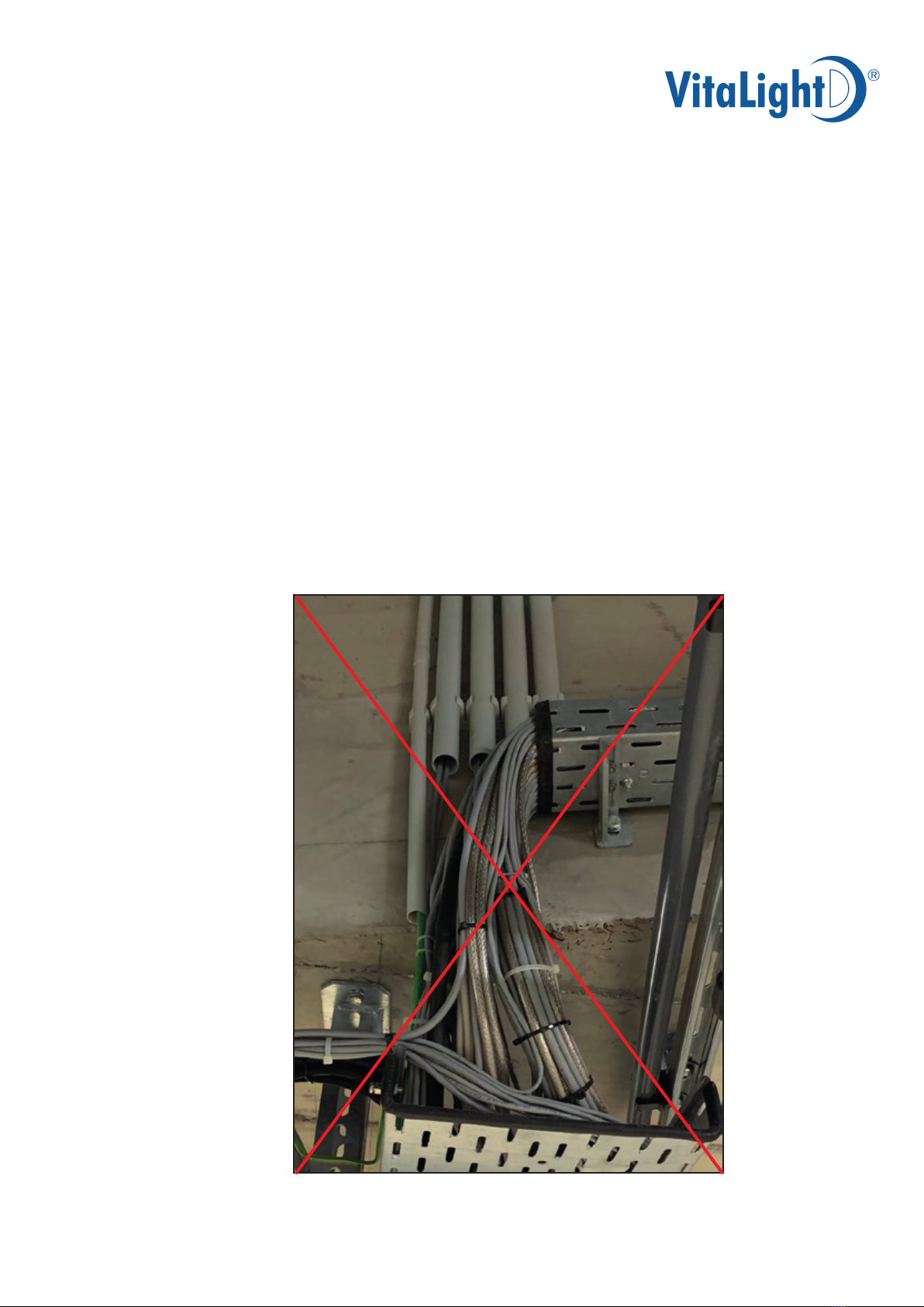
3. Die zwei Anschlusskabel durch die Kabelverschraubungen am Abschlussdeckel führen. Ausreichend Kabel im Unter-
wasserfenster aufgerollt lassen, um Wartungsarbeiten durchführen zu können.
Achtung: Beim Einbau in einem Unterwasserfenster Ø 250 mm sind die Füße am Einschub-Scheinwerfer zu demontieren!
Bei der Montage ist zwingend darauf zu achten, dass die Anschlusskabel nicht beschädigt werden!
Die offenen Kabelenden dürfen niemals mit Wasser in Berührung kommen!
4. Versorgungseinheit an der Wand im Technikgang anbringen.
5. Anschlüsse an der Versorgungseinheit laut Anschlussplan ausführen.
6. Abschlussdeckel der Fensteröffnung wieder korrekt positionieren und befestigen.
Achtung: Bei einer einfachen Verglasung des Unterwasserfensters muss der Abschlussdeckel wieder korrekt positioniert
und befestigt werden, um bei einem Glasbruch an der Fensterfront ein Einströmen des Schwimmbadwassers in den
Technikgang zu verhindern!
Installation instruction:
1. Open the locking cover of the underwater window from the technical passage.
2. Put the floodlight insertion into the underwater window, position it and move it towards the glass plate.
3. Put the two connection cables through the cable gland on the locking cover. Keep sufficient cable in the underwater
window for being able to do maintenance work.
Attention: When installing into an underwater window Ø 250 mm the feet of the floodlight insertion module have to
be disassembled! During installation it has to be ensured that the connection cables do not get damaged!
The open cable heads must never come into contact with water!
4. Attach the supply unit on the wall in the technical passage.
5. Conduct the connections on the supply unit according to the wiring diagram.
6. Reposition the locking cover of the aperture correctly and re-fix it.
Attention: In case of single pane windows the locking cover has to be correctly repositioned and re-fixed for avoiding
an influx of the pool water into the technical passage in case of a glass breakage.

4
a brand of Hugo Lahme GmbH
Stand 08/2020 Art.-Nr.: 579191
Elektrischer Anschluss / Electric connection / Branchement électrique /
Conexiones eléctricas
Der Einschub-Scheinwerfer darf nur mit einer Versorgungseinheit der Firma HUGO LAHME betrieben werden. Bei der Installation
ist die DIN VDE 0100-701 und 702 zu beachten. Gemäß VDE 0100-430 sind alle Kabel bauseits gegen Überlastung zu schützen.
Die Betriebsspannung des Leuchtmittels darf 24 V DC nicht überschreiten.
Damit die Datenübertragung zu den Unterwasserscheinwerfern nicht gestört bzw. beeinträchtigt wird, muss das Anschlusskabel
sowie die Kabelverlängerung von der Versorgungseinheit zum Unterwasserscheinwerfer getrennt von anderen leistungsführenden
Leitungen verlegt werden. Nicht wie im Bild dargestellt! Unter Umständen sind getrennte EMV Schutzrohre/-schläuche zu
verwenden!
Die Installation darf nur von einer zugelassenen Elektrofachkraft vorgenommen werden.
Versorgungseinheit / supply unit / boîtier d'alimentation /
Caja de alimentación
Der Anschluss darf nur gemäß DIN EN 61558/VDE 0570, DIN EN 61347/VDE 0712,VDE 0100 Teil 410 erfolgen.
Connection is only to be made at a safety controller according to DIN EN 61558/VDE 0570 DIN EN 61347 VDE 0712, VDE 0100
part 410.
Les appareils d’alimentation / ballast à utiliser sont de sécurité selon les normes DIN EN 61558/VDE 0570, DIN EN 61347/VDE
0712 / VDE 0100 chapitre 410.
La conexión sólo debe hacerse según las normas DIN EN 61558/VDE 0570, DIN EN 61347/VDE 0712 /VDE 0100 parte 410.
Montage dans le bassin
1. De la galerie technique ouvrir le couvercle de la fenêtre subaquatique.
2. Pose du module dans la fenêtre subaquatique et positionner celui-ci jusqu’à la vitre de fermeture.
3. Introduire les deux câbles dans les presses étoupes du couvercle, prévoir assez de câble dans le boîtier pour
maintenance.
Attention:
En cas d'utilisation d'un fenêtre subaquatique avec Ø 250 mm les deux pieds en équerre sont à démonter !
Pour le remontage il est important que le couvercle soit bien positionné et de faire très attention que les câbles ne soit
pas endommagés ! Les extrémités nues des câbles ne doivent jamais entrer en contact avec de l’eau!
4. Fixer l’alimentation au mur de la galerie technique.
5. Branchement à effectuer suivant le schéma.
6. Mise en place du couvercle de fermeture de fenêtre et fixation.
Attention: En cas de fenêtre de projecteur avec un verre simple de fermeture bien repositionner le couvercle de fermeture
de manière qu’en cas de rupture d’étanchéité l’eau de piscine ne puisse pas s’écouler dans la galerie technique.
Instrucciones de montaje
1. Abrir la tapa de cierre de la ventana submarina desde el pasillo para la técnica.
2. Colocar el foco insertable en la ventana submarina, ubicarlo y empujarlo hasta el cristal.
3. Pasar los dos cables de conexión por los racores para cable de la tapa de conexión. Dejar bastante cable enrollado en la
ventana submarina, para poder realizar las tareas de mantenimiento.
Atención: ¡Al montar en una ventana submarina de Ø 250 mm hay que desmontar los pies en el foco insertable! ¡Es
imprescindible prestar atención en el montaje a que no se dañen los cables de conexión! ¡Los extremos abiertos de los
cables no deben entrar nunca en contacto con agua!
4. Colocar la unidad de abastecimiento en la pared en el pasillo para la técnica.
5. Tender las conexiones en la unidad de abastecimiento según el esquema de conexión.
6. Ubicar de nuevo la tapa de conexión correctamente en el orificio de la ventana y sujetar.
Atención: ¡Con un acristalado simple de la ventana submarina, hay que ubicar y sujetar correctamente la tapa de
conexión, para que en caso de rotura del cristal se evite que el agua de la piscina entre en el pasillo para la técnica!

5
a brand of Hugo Lahme GmbH
Stand 08/2020 Art.-Nr.: 579191
The floodlight insertion module may only be used in connection with a supply unit from Hugo LAHME. All construction and cables
have to be protected against overloading (provided by customer). Do not exceed the operating voltage of the lamps (24 V DC).
To ensure that data transmission to the underwater spotlights is not disturbed or impaired, the connector cable and the cable
extension from the supply unit to the underwater spotlight must be laid separately from other power cables. Not as shown in the
picture! Under certain circumstances, separate EMC shielded tubes or hoses must be used!
The installation work has to be conducted by a certified electrician.
Les projecteurs por hublot local technique ne doivent être raccordés qu’avec un boîtier d’alimentation de la société HUGO LAHME.
L’installation doit être réalisée suivant la norme C 15-100 VDE 0100-430 disant que tous les câbles sont à protéger contre une
surtension. La tension nominale des sources (24 V DC) est impérativement à respecter.
Afin de ne pas perturber la transmission de données vers les projecteurs aquatiques, le câble de raccordement et la rallonge
reliant l’unité d’alimentation et le projecteur aquatique doivent être posés séparément des autres câbles conducteurs. Pas comme
l’illustration ! Le cas échéant, utilisez tuyaux/tubes de protection CEM séparés !
L’installation doit être effectuée uniquement par du personnel qualifié.
Los focos insertables no deben ser conectados más que con una caja de alimentación de la marca HUGO LAHME. La instalación
debe realizarse siguiendo la norma C 15-100 VDE0100-430 que indica que todos los cables deber protegerse contra una subida de
tensión. No exceder La tensión nominal de las fuentes (24 V DC).
Para que la transmisión de datos a los focos subacuáticos no esté interrumpida o tenga interferencias hay que tender el cable de
conexión y la prolongación de la unidad de abastecimiento hacia el foco separados de otros conductos. ¡No como se muestra en
la figura ! ¡En determinadas circunstancias debe usar tubos / mangueras de protección CEM!
La instalación debe ser realizada únicamente por personal calificado.
Bild / figure / photo / foto
falsch / wrong / faux / mal

6
a brand of Hugo Lahme GmbH
Stand 08/2020 Art.-Nr.: 579191
Monochrom (nicht dimmbar) / Monochrome (not dimmable) /
Monochrome (sans variateur de lumière) / Monocromo (sin claridad regulable)
N = Neutralleiter / Neutral / Neutre / Neutro
L1 = Phase, Netz / Maine / Phase / Fase
D = Netzteil / Power supply unit / Appareil d’alimentation / Aparato de alimentación
40600050 (monochrom / monochrome / monochrome / monocromo)
E = Taster / Push button / Bouton-poussoir / Pulsador
F = Sicherung / Fuse / Protection / Protección
PE = Erdung / Grounding / Terre / Tierra
220 - 240V/AC
L1
N
PE
+24V
-Gnd
Lüfter + (1)
Lüfter - (2)
+24V
-Gnd
Lüfter + (1)
Lüfter - (2)
F 10/16A
D
E
+24V DC
Elektrischer Anschlussplan / Electrical connection diagram
Schéma de branchement / Esquema de conexión
Kabelbelegung
Cable configuration
Branchement des câbles
Conexión de los cables
24V DC + braun / brown / brun / marrón
Gnd - blau / blue / bleu / azul
Achtung / Attention / Attention / Atención
Eine falsche Anschlussbelegung zerstört den Einschub-Scheinwerfer.
An incorrect clamping destroys the floodlight insertion module.
Un mauvais branchement détruit le module projecteur.
Una asignación falsa de las conexiones destruye el foco insertable.
100 - 240V/AC
+24V DC

7
a brand of Hugo Lahme GmbH
Stand 08/2020 Art.-Nr.: 579191
RGBW / RGBW / RGBW / RGBW
N = Neutralleiter / Neutral / Neutre / Neutro
L1 = Phase, Netz / Maine / Phase / Fase
D = Vorschaltgerät / Ballast / Ballast / Ballast
40600150 (RGBW / RGBW / RGBW / RGBW)
E = Taster / Push button /
Bouton-poussoir / Pulsador
F = Sicherung / Fuse / Protection / Protección
PE = Erdung / Grounding / Terre / Tierra
Kabelbelegung
Cable configuration
Branchement des câbles
Conexión de los cables
24V DC + braun / brown / brun / marrón
Gnd - blau / blue / bleu / azul
Lüfter + schwarz / black / noir / negro
Lüfter - grau / grey / gris / gris
220 - 240V/AC
L1
N
PE
+24V
-Gnd
Lüfter + (1)
Lüfter - (2)
+24V
-Gnd
Lüfter + (1)
Lüfter - (2)
F 10/16A
D
E
+24V DC
Elektrischer Anschlussplan / Electrical connection diagram
Schéma de branchement / Esquema de conexión
Achtung / Attention / Attention / Atención
Eine falsche Anschlussbelegung zerstört den Einschub-Scheinwerfer.
An incorrect clamping destroys the floodlight insertion module.
Un mauvais branchement détruit le module projecteur.
Una asignación falsa de las conexiones destruye el foco insertable.
100 - 240V/AC
+24V DC

8
a brand of Hugo Lahme GmbH
Stand 08/2020 Art.-Nr.: 579191
ACHTUNG! Die Installation darf nur von einer zugelassenen Elektrofachkraft vorgenommen werden. Die Installa-
tionsvorschriften des zuständigen EVUs und der DIN VDE 0100- 702 sind zu beachten. Die Zuleitung
zur Versorgungseinheit ist mit einem Kabelquerschnitt von mindestens 3 x 1,5 mm² zu verlegen. Nach
VDE 0100,Teil 701, Abschnitt 4.1.3 muss ein Fi-Fehlerstrom-Schutzschalter mit 30 mA bauseits gestellt
werden. Der Deckel der Versorgungseinheit darf nur bei spannungslosem Zustand geöffnet werden. Für
alle Arbeiten an der Versorgungseinheit muss die Versorgungsspannung abgeschaltet werden.
Hinweis: Installation der Versorgungseinheit nur in trockenen Räumen. Die Umgebungstemperatur darf 40°C nicht
überschreiten. Mindestabstand zwischen den Versorgungseinheiten 100 mm.
ATTENTION! The installation may only be operated by admitted experts. The installation regulations of the responsible
Energy Supply Company have to be followed. A cable with a cable cross section of at least 3 x 1.5 mm²
has to be connected with the supply ballast unit. A residual current device (RCD) with 30 mA has to be
installed (on site). Do only open the cover of the supply unit in a disconnected status. For all working at
the supply unit, stop the supply voltage.
Assembly tip: Installation of the supply unit only in dry places. The surrounding temperature may not exceed 40°C.
Minimum distance between the supply ballast units 100 mm
ATTENTION! L’installation ne doit être effectuée que par un électricien agrée. L’installation doit être réalisée suivant les
normes locales. Le câble d'alimentation au primaire ne doit pas avoir une section du câble inférieure à 3 x
1,5 mm² et être protégée en amont par une protection différentielle par défaut calibré à 30 mA (à procurer
sur les lieux) suivant la norme. Le capot de fermeture de l'alimentation ne doit être ouvert que hors ten-
sion. Pour toute intervention à l’intérieur du boîtier le courant d'alimentation doit être coupé.
Info: Placer le boîtier d’alimentation de projecteur de piscine dans un endroit sec. La température ambiante ne doit pas être
supérieure à 40°C, l’espace minimum entre les alimentations ne doit pas être inférieure à 100 mm.
ATENCIÓN! La instalación sólo debe ser realizada por un electricista experto. La instalación debe ser realizada siguien-
do las normativas locales. El cable de alimentación del primario no debe tener una sección de cable infe-
rior a 3 x 1.5 mm2y protegida por una protección diferencial por defecto calibrada a 30 mA (en el lugar de
instalación) siguiendo la norma. La tapa de la caja de alimentación no debe abrirse cuando está conectada
la tensión. Para cualquier intervención en el interior de la caja se debe previamente cortar la corriente.
Info: Colocar la caja de alimentación del foco en un lugar seco. La temperatura ambiente no debe ser superior a 40ºC, el espacio
mínimo entre las alimentaciones no debe ser inferior a 100 mm.
ACHTUNG! / ATTENTION! / ATTENTION! / ATENCIÓN!
Sollte ein Defekt an der Versorgungseinheit oder am Einschub-Scheinwerfer auftreten, ist eine fachgerechte
Reparatur nur durch den Hersteller zulässig.
In case of damage of the module’s floodlight or a control element, only professional reparation by the manu-
facturer is allowed.
En cas de panne de composants ou de module une réparation par l’utilisateur ne sera pas reconnue, celle-ci ne
doit être effectuée que par le fabricant.
En caso de avería de los componentes o del focos insertables sólo se aceptarán reparaciones realizadas por
el fabricante.

9
a brand of Hugo Lahme GmbH
Stand 08/2020 Art.-Nr.: 579191
Art.-Nr. / Code Artikelbezeichnung / Product type
Réf. / Ref Type de produit / Tipo de producto
40600050
monochrom
monochrome
monochrome
monocromo
Netzteil 100-240V AC / 24V DC, 200 W, 50/60Hz,
für 2 Einschub-Scheinwerfer 28er POWER LED 3.0
Power supply unit 100-240V AC / 24V DC, 200 W, 50/60Hz,
for 2 floodlight insertion modules 28 POWER LED 3.0
Appareil d'alimentation 100-240V AC / 24V DC, 200 W, 50/60Hz,
pour 2 modules de projecteur 28 POWER LED 3.0
Aparato de alimentación 100-240V AC / 24V DC, 200 W, 50/60Hz,
para 2 focos insertables 28 POWER LED 3.0
40600150
RGBW
RGBW
RGBW
RGBW
Vorschaltgerät 100-240V AC / 24V DC, 200 W, 50/60Hz
für 2 Einschub-Scheinwerfer 28er POWER LED 3.0
Master-Slave und Busfunktionalität Grundversion 230-12V/DC
Ballast 100-240V AC / 24V DC, 200 W, 50/60Hz
for 2 floodlight insertion modules 28 POWER LED 3.0
master-slave and bus connection basic model 230-12V/DC
Ballast 100-240V AC / 24V DC, 200 W, 50/60Hz
pour 2 modules de projecteur 28 POWER LED 3.0
master et slave par bus modèle de base 230-12V/DC
Ballast 100-240V AC / 24V DC, 200 W, 50/60Hz
para
2 focos insertables
28 POWER LED 3.0
Funcionalidad máster-slave y de bus versión básica 230-12V/CC
40000050
Funkfernbedienung, Funkempfangsmodul (Einsteckmodul) mit Antenne und Antennenkabel
Remote control, Remote control-receiver module with aerial and aerial-cable
Télécommande et module de réception de signal télécommande avec antenne et câble
Mando a distancia- módulo de recepción con antena y cable
576841
DMX 512 Einsteckmodul mit Interfacekabel
DMX 512 module
Adaptateur DMX 512 module à coupler avec le ballast
Adaptador DMX 512 módulo a acoplar con el ballast
Zubehör
Accessories
Accessoires
Accesorios

10
a brand of Hugo Lahme GmbH
Stand 08/2020 Art.-Nr.: 579191
Technische Änderungen vorbehalten Technical amendments reserved
Modifications techniques sous réserve Nos reservamos el derecho a las modificaciones técnicas
Grenzwerte im Schwimmbadwasser für Rotgusseinbauteile und Edelstahlarmaturen:
• Entkeimungsmittelgehalt bis 1,0 mg/l • Chloridgehalt bis 500 mg/l • pH-Wert 6,5 - 9,5
Bei der Verwendung von Bronzeeinbauteilen gilt ein Grenzwert von 6% Salzgehalt.
Salzelektrolysegeräte, die nach dem Prinzip des Durchlaufverfahrens arbeiten, benötigen im Schwimmbadwasser einen Salzgehalt
von mindestens 0,35%. Diese Salzmenge entspricht einem Wert von 2.135 mg/l Chlorid. Bei Verwendung dieser Systeme dürfen
daher nur Armaturen aus Bronze verwendet werden. Bei Verwendung von Rotguss in Verbindung mit Salzelektrolysegeräten
erlischt jeglicher Gewährleistungsanspruch. Bei Verwendung ungeregelter Salzelekrolysegeräte erlöschen sämtliche Gewährleis-
tungsansprüche.
Gun metal installation components and stainless steel fittings can be utilised up to the following pool water limits:
• Disinfectant content up to 1.0 mg/l • Chloride content up to 500 mg/l • pH value 6.5 - 9.5
When using bronze installation parts the threshold is 6% salt content.
Salt electrolysis systems working by the through-feed method need a salinity of 0.35 % in the pool water. This salinity is equal
to 2.135 mg/l chloride. Using such systems it is only allowed to use fittings made out of bronze. If using gun-metal with salt
electrolysis any warranty will expire. Using unregulated salt electrolysis all guarantee claims dispense.
Les éléments et pièces à sceller en laiton rouge et les robinetteries en acier inoxydable peuvent être utilisés jusqu’à ces
limites d’eau de piscine :
• Teneur en désinfectant jusque 1.0 mg/l • Chlorures jusque 500 mg/l • pH 6.5 - 9.5
Pour l’utilisation de composants en bronze le seuil est de 6% teneur en sel.
Les électrolyseurs au sel qui fonctionnent selon le principe du processus continu nécessitent que l’eau de piscine ait une teneur
en sel d’au moins 0,35 %. Cette quantité de sel correspond à une valeur de 2,135 mg/l de chlorure. L’utilisation de ces systèmes
nécessite d’utiliser exclusivement des robinetteries en bronze. L’utilisation de bronze autrichien avec des électrolyseurs au sel
annule tout droit de garantie. L’utilisation d’électrolyseurs au sel déréglés annule tous les droits de garantie.
Los elementos y nichos en bronce y griferías de acero inoxidable pueden utilizarse hasta los siguientes límites en el
agua de la piscina:
• Contenido en desinfectante hasta 1.0 mg/l • Cloruros hasta 500mg/l • pH 6.5 - 9.5
Por encima de un 6% de contenido en sal, utilizar elementos y nichos en bronce GBZ.
Cloradores de agua salada que trabajan con el principio del proceso continuo necesitan un porcentaje mínimo del 0,35 % de sal
en el agua de la piscina. Esa cantidad de sal corresponde a un valor de 2.135 mg/l de cloruro. Si se utiliza ese sistema solamente
se deben utilizar griferías de bronce. Si se utiliza latón en combinación con cloradores de agua salda se pierde todo derecho a
garantía. El uso de cloradores de agua salada no regulados conlleva la pérdida completa de la garantía.
Achtung / Attention / Attention / Atención

11
a brand of Hugo Lahme GmbH
Stand 08/2020 Art.-Nr.: 579191
Hugo Lahme GmbH | Kahlenbecker Str. 2 | 58256 Ennepetal | Germany
Hausanschrift:
Hugo Lahme GmbH
Kahlenbecker Str. 2
58256 Ennepetal
Germany
Telefon: +49 (0) 23 33 / 96 96 0
Telefax: +49 (0) 23 33 / 96 96 46
Internet: www.lahme.de
Geschäftsführer:
Hans-Joachim Wittwer
Werner Markenstein
Amtsgericht Hagen HRB 5798
USt-IdNr.: DE 812212582
Steuer-Nr.: 341/5710/0056
WEEE-Reg.-Nr. DE 45883980
Bankverbindungen:
Sparkasse Ennepetal (BLZ 454 510 60) 620
IBAN: DE78 4545 1060 0000 0006 20
BIC: WELADED1ENE
Deutsche Bank Schwelm (BLZ 330 700 90) 37 555 0100
IBAN: DE15 3307 0090 0375 5501 00
BIC: DEUTDEDW334
Halle 10.1, Stand G030
EG-Konformitätserklärung
EC declaration of conformity
Die Firma / The company
Hugo Lahme GmbH
Kahlenbecker Str. 2
58256 Ennepetal
erklärt hiermit, dass die Unterwasserscheinwerfereinsätze
Herewith we declare that the underwater floodlight insets
VitaLight®
2x28er / 28er POWER LED 3.0 Art.-Nr. / Code 4.44640050 4.44641050
2x28 / 28er POWER LED 3.0 4.44640250 4.44641250
4.44640350 4.44641350
4.44640450 4.44641450
folgenden einschlägigen Bestimmungen entspricht:
complies with the following provisions applying to it:
EMV-Richtlinie 2014/30/EU
EG-Richtlinie 2014/35/EU (Niederspannungsrichtlinie)
EG-Richtlinie 2012/19/EU (WEEE)
EG-Richtlinie 2011/65/EG (RoHS)
Angewendete harmonisierte Normen, insbesondere
Applied harmonized standard in particular
DIN EN 60598-2-18; VDE 0711-2-18: 2012-09
DIN EN 62031; VDE 0715-5: 2015-09
DIN EN 62471 + Beiblatt 1; VDE0837-471: 2009-03 + Beiblatt 1: 2010-06
DIN EN 55015; VDE 0875-15-1: 2016-04
DIN EN 61000-3-2; VDE 0838-2: 2015-03
DIN EN 6100-3-3; VDE 0838-3: 2014-03
DIN EN 61547; VDE 0875-15-2: 2010-03; Berichtigung 1:2010-07
Wir erklären in alleiniger Verantwortung, dass das Produkt, auf das sich diese Erklärung bezieht,
den obigen Spezifikationen entspricht.
We declare under our sole responsibility that the product to which this declaration relates is in conformity with the above
specifications.
Bei einer mit uns nicht abgestimmten technischen Änderung der oben genannten Produkte, verliert
diese Erklärung ihre Gültigkeit.
This declaration becomes invalid, in case of any technical modification without our approval.
Ennepetal, August 2019 i.V. Johannes Hafer i.A. Dirk Langwieler
Qualitätswesen / Quality Management Leiter Technik / Head of Technology

12
a brand of Hugo Lahme GmbH
Stand 08/2020 Art.-Nr.: 579191
brands of Hugo Lahme GmbH
Hugo Lahme GmbH · Kahlenbecker Straße 2 · D-58256 Ennepetal · Germany
Telefon +49 (0) 23 33 / 96 96-0 · Telefax +49 (0) 23 33 / 96 96 46
Hugo Lahme
Perfektion in jedem Element.
Table of contents
Other Hugo Lahme Underwater Lighting manuals
Popular Underwater Lighting manuals by other brands

Ros
Ros SCE-X Operation and maintenance manual

Backscatter
Backscatter Mini Flash MF-1 instruction manual

Oceanled
Oceanled Explore E7 Series Installation & operation manual

OMD
OMD 5000w Tungsten Instructions for use

IGNIA LIGHT
IGNIA LIGHT STARRY SKY Installation and maintenance manual

emaux
emaux UL-P300 Series user manual