Hukseflux FHF05SC Series User manual

FHF05SC series manual v2203 2/43
Cautionary statements
Cautionary statements are subdivided into four categories: danger, warning, caution and
notice according to the severity of the risk.
DANGER
Failure to comply with a danger statement will lead to death or serious
physical injuries.
WARNING
Failure to comply with a warning statement may lead to risk of death or
serious physical injuries.
CAUTION
Failure to comply with a caution statement may lead to risk of minor or
moderate physical injuries.
NOTICE
Failure to comply with a notice may lead to damage to equipment or may
compromise reliable operation of the instrument.

FHF05SC series manual v2203 3/43
Contents
Cautionary statements 2
Contents 3
List of symbols 4
Introduction 5
1Ordering and checking at delivery 9
1.1 Ordering FHF05SC series 9
1.2 Included items 9
1.3 Quick instrument check 10
2Instrument principle and theory 11
2.1 Theory of operation 11
2.2 The self-test 14
2.3 Calibration 14
2.4 Application example: stable performance check 15
2.5 Application example: non-invasive core temperature measurement 18
3Specifications of FHF05SC series 19
3.1 Specifications of FHF05SC series 19
3.2 Dimensions of FHF05SC series 22
4Standards and recommended practices for use 23
4.1 Heat flux measurement in industry 23
5Installation of FHF05SC series 24
5.1 Site selection and installation 24
5.2 Installation on curved surfaces 26
5.3 Electrical connection 27
5.4 Requirements for data acquisition / amplification 30
6Maintenance and trouble shooting 31
6.1 Recommended maintenance and quality assurance 31
6.2 Trouble shooting 32
6.3 Calibration and checks in the field 34
7Appendices 35
7.1 Appendix on cable extension 35
7.2 Appendix on using FHF05SC series with BLK – GLD sticker series 36
7.3 Appendix on standards for calibration 37
7.4 Appendix on calibration hierarchy 37
7.5 Appendix on correction for temperature dependence 38
7.6 Appendix on measurement range for different temperatures 39
7.7 Appendix on temperature measurement accuracy 40
7.8 EU declaration of conformity 42

FHF05SC series manual v2203 4/43
List of symbols
Quantities Symbol Unit
Heat flux ΦW/m²
Voltage output U V
Sensitivity S V/(W/m2)
Temperature T °C
Thermal resistance per unit area Rthermal,A K/(W/m²)
Area A m²
Electrical resistance R Ω
Electrical power P W
subscripts
property of heatsink heatsink
property of heater heater
property of sensor sensor
maximum value, specification limit maximum

FHF05SC series manual v2203 5/43
Introduction
FHF05SC series is a combination of the standard model FHF05 heat flux sensor and a
heater. The heater allows the user to perform self-tests, verifying sensor functionality
and stability during use, without having to remove the sensor. FHF05SC series are ideal
for high-accuracy and long-term heat flux measurement, construction of calorimeters,
(zero heat flux) core temperature measurement and thermal conductivity test
equipment. Available in two models: size 50X50 mm and a larger size of 85X85 mm.
FHF05SC series measures heat flux through the object in which it is incorporated or on
which it is mounted, in W/m2. The sensor within is a thermopile. This thermopile
measures the temperature difference across FHF05SC’s flexible body. A type T
thermocouple is integrated as well to provide a temperature measurement. The
thermopile and thermocouple are passive sensors; they do not require power.
Multiple small thermal spreaders, which form a conductive layer covering the sensor,
help reduce the thermal conductivity dependence of the measurement. With its
incorporated spreaders, the sensitivity of FHF05SC series is independent of its
environment. Many competing sensors do not have thermal spreaders. The passive guard
area around the sensor reduces edge effects and is also used for mounting. Looking for
only heat flux and temperature measurement without a heater? See our FHF05 series heat
flux sensors.
Figure 0.1 Model FHF05SC-50X50 self-calibrating foil heat flux sensor with thermal
spreaders and heater, showing its back and front side.

FHF05SC series manual v2203 6/43
Measuring heat flux, users may wish to regularly check their sensor performance. During
use, the film heater is activated to perform a self-test. The heat flux sensor response to
the self-test results in a verification of sensor performance. Implicitly also wire
connection, data acquisition, thermal connection of the sensor to its environment and
data processing are tested. Heat flux sensors are often kept installed for as long as
possible. Using self-testing, the user no longer needs to take sensors to the laboratory to
verify their stable performance. In a laboratory environment, using a metal heat sink,
you may even perform a formal calibration. The heater has a well characterised and
traceable surface area and electrical resistance.
The FHF05SC series self-calibrating foil heat flux sensor has unique features and
benefits:
•heater for self-test
•flexible (bending radius ≥ 15 x 10-3 m)
•low thermal resistance
•wide temperature range
•fast response time
•integrated type T thermocouple
•robustness, including cable and connection block which may be used as strain relief
•IP protection class: IP67 (essential for outdoor application)
•integrated thermal spreaders for low thermal conductivity dependence
FHF05SC series suggested use:
•high-accuracy scientific measurement of heat flux, with a high level of data quality
assurance
•study of convective heat transfer mechanisms
•calorimeter prototyping
•(zero heat flux) non-invasive core temperature measurement
•thermal conductivity test equipment
\
Figure 0.2 Application example: FHF05SC-50X50 being installed to measure heat flux on
a pipe. The sensor is mounted on a well-prepared curved surface.

FHF05SC series manual v2203 7/43
Using FHF05SC series is easy. It can be connected directly to commonly used data logging
systems. The heat flux in W/m2is calculated by dividing the sensor output, a small voltage,
by the sensitivity. The sensitivity is provided with FHF05SC series on its product certificate.
Equipped with a protective potted connection block, which may serve as strain relief so
that moisture does not penetrate, FHF05SC series has proven to be very robust and
stable.
FHF05SC series calibration is traceable to international standards. The factory calibration
method follows the recommended practice of ASTM C1130 - 21. When used under
conditions that differ from the calibration reference conditions, the FHF05SC series
sensitivity to heat flux may be different than stated on its certificate. See Chapter 2 in
this manual for suggested solutions.
Would you like to study energy transport / heat flux in detail? Hukseflux helps taking this
measurement to the next level: order FHF05SC series with radiation-absorbing black and
radiation-reflecting gold stickers. You can then measure convective + radiative flux with
one, and convective flux only with the other. Subtract the 2 measurements and you have
radiative flux. They can be applied to the sensor by the user or at the factory; see the BLK
– GLD sticker series user manual and installation video for instructions.
Figure 0.3 FHF05SC-50X50 heat flux sensor: with BLK-5050 and GLD-5050 stickers.

FHF05SC series manual v2203 8/43
See also:
•FHF05 series, our standard model for general-purpose heat flux measurement
•model HFP01 for increased sensitivity (also consider putting two or more FHF05s in
series)
•HTR02 series heater, for calibration and verification of performance of FHF-type sensors.
•BLK - GLD sticker series to separate radiative and convective heat fluxes
•Hukseflux offers a complete range of heat flux sensors with the highest quality for any
budget

FHF05SC series manual v2203 9/43
1Ordering and checking at delivery
1.1 Ordering FHF05SC series
The standard configuration of FHF05SC series is FHF05SC-50X50-02, model 50X50 with
2 metres of cable. Common options are:
•model FHF05SC-85X85
•change -02 to -05 or -10 metres cable length
•with a separate cable in 2, 5 or 10 metres cable length
•with LI19 hand-held read-out unit / datalogger; NOTE: LI19 does not measure
temperature, only heat flux and does not support self-test functionality
•BLK black sticker (to measure radiative as well as convective heat flux)
•GLD gold sticker (to measure convective heat flux only)
•BLK - GLD sticker series can also be ordered pre-applied at the factory for every
sensor dimension
1.2 Included items
Arriving at the customer, the delivery should include:
•heat flux sensor FHF05SC with cable of the length as ordered
•product certificate matching the instrument serial number
Figure 1.2.1 Model FHF05SC-50X50 with serial number and sensitivity shown at the end
of the cable.

FHF05SC series manual v2203 10/43
1.3 Quick instrument check
A quick test of the instrument can be done by connecting it to a multimeter.
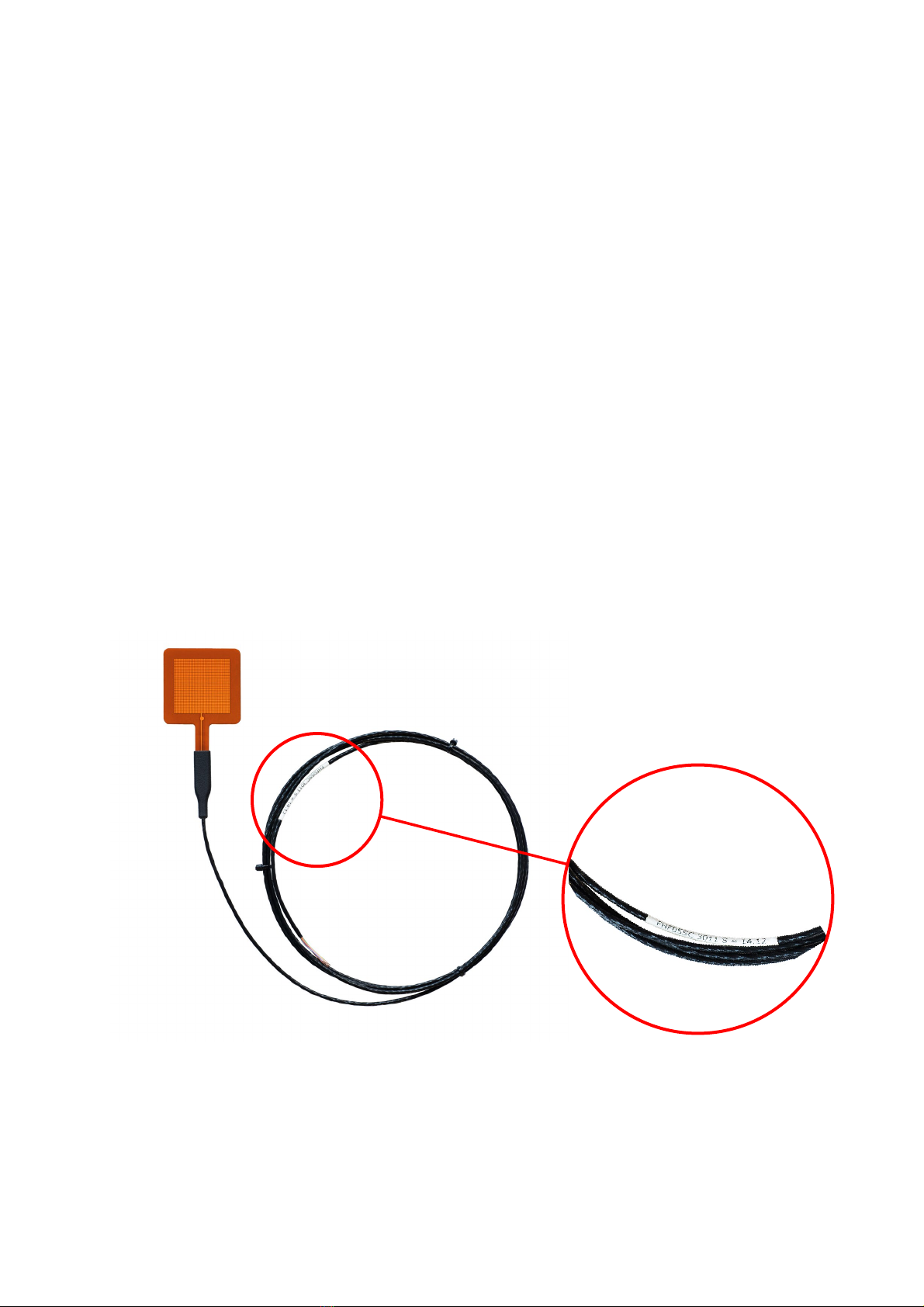
1. Check the sensor serial number and sensitivity on the sticker on the potted connection
block against the product certificate provided with the sensor.
2. Inspect the instrument for any damage.
3. Check the electrical resistance of the sensor between the red [+] and black [-] wires.
Use a multimeter at the 1k Ω range. Measure the sensor resistance first with one
polarity, then reverse the polarity. Take the average value. The typical resistance of the
wiring is 0.3 Ω/m. Typical resistance should be the nominal sensor resistance mentioned
in table 3.1.1 plus 0.6 Ω for the total resistance of two wires for each metre (back and
forth). Infinite resistance indicates a broken circuit; zero or a lower than 1 Ω resistance
indicates a short circuit.
4. Check the electrical resistance of the thermocouple between the brown [+] and white
[-] wires. Use a multimeter at the 100 Ω range. Measure the thermocouple resistance
first with one polarity, then reverse the polarity. Take the average value. The typical
resistance of the copper wiring is 0.3 Ω/m, for the constantan wiring this is 6.5 Ω/m.
Typical resistance should be the nominal thermocouple resistance of 2.5 Ω plus 6.8 Ω for
the total resistance of the two wires of each metre (back and forth). Infinite resistance
indicates a broken circuit; zero or a lower than 1 Ω resistance indicates a short circuit.
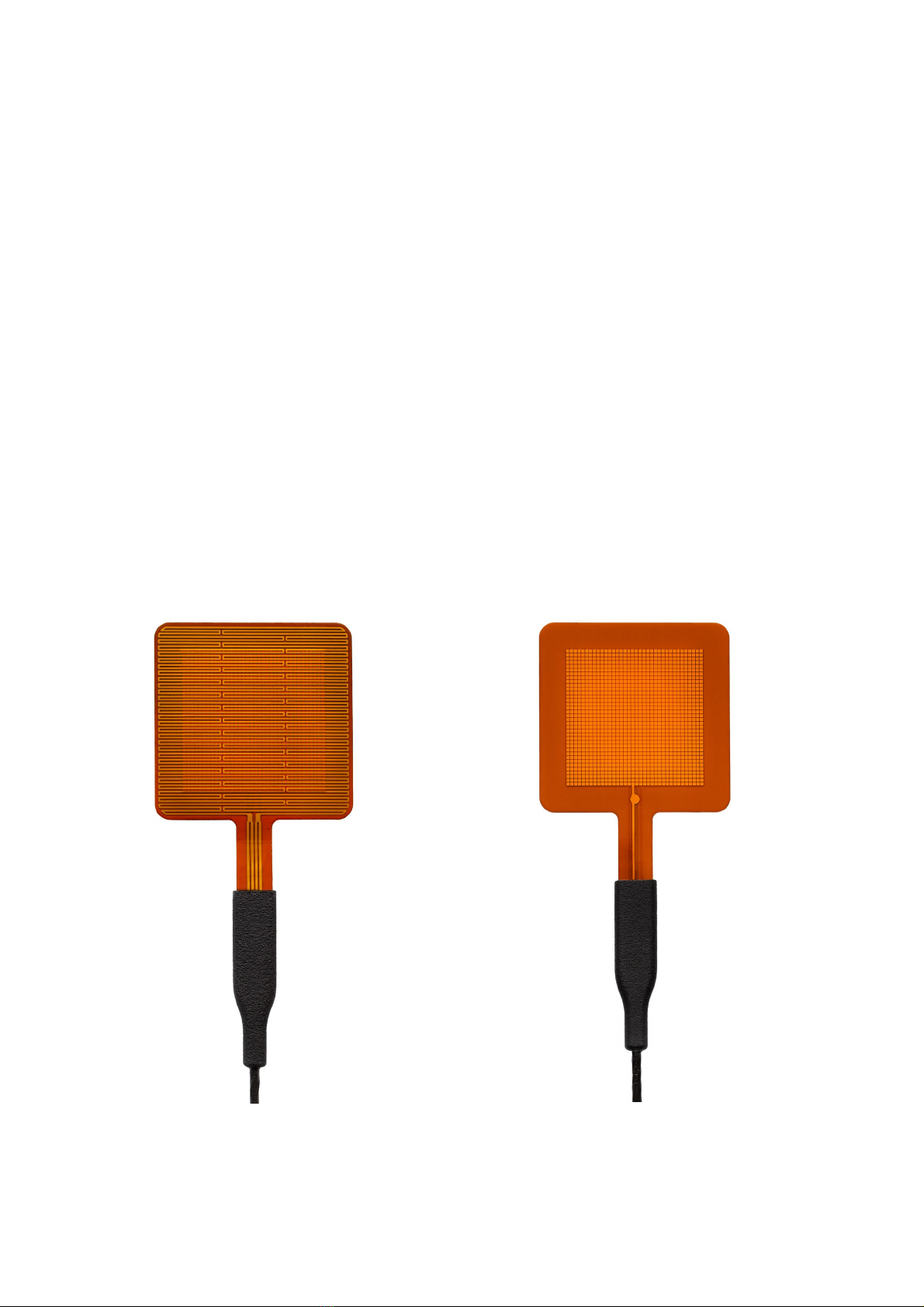
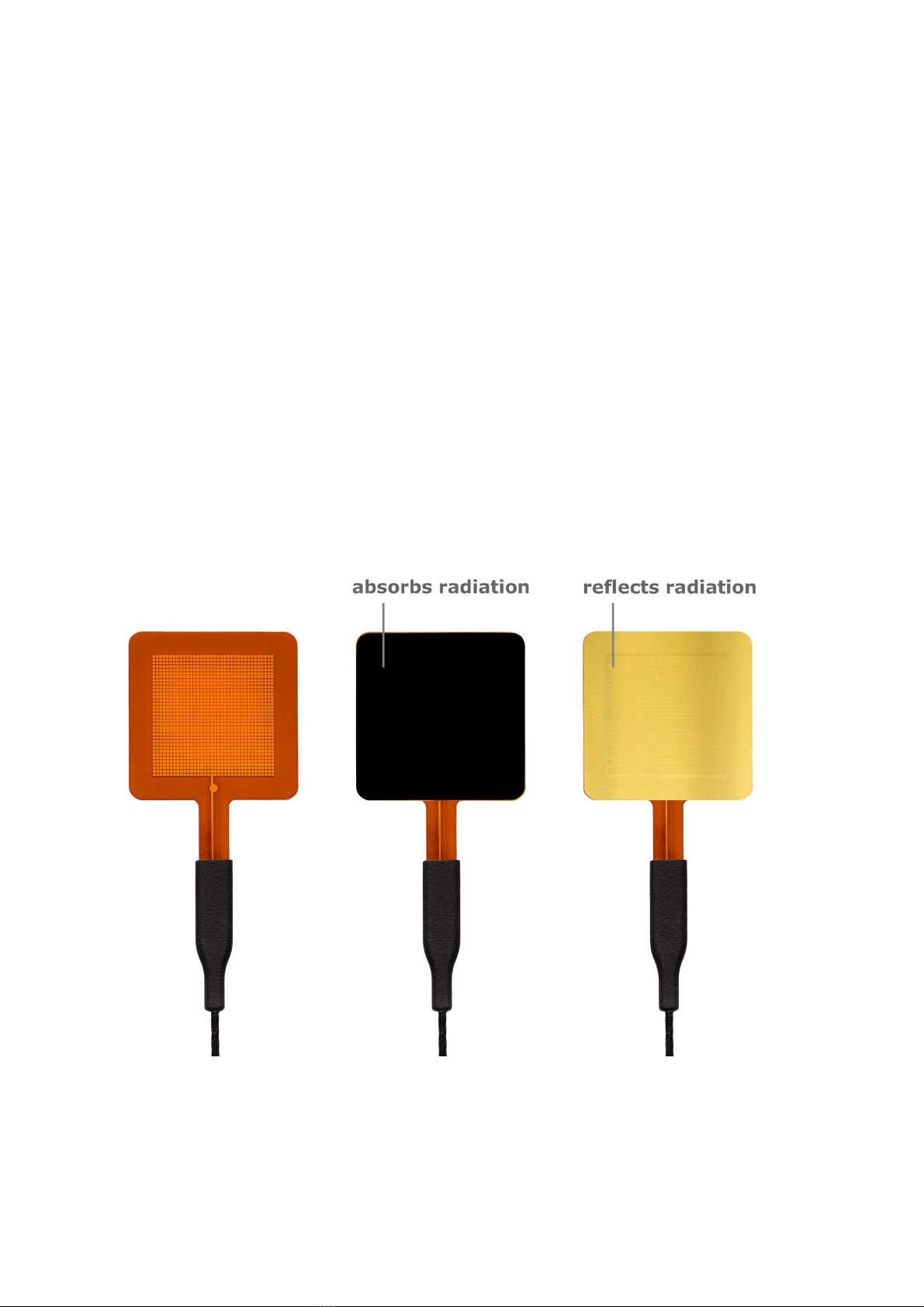
5. Check if the sensor reacts to heat: put the multimeter at its most sensitive range of
DC voltage measurement, typically the 100 x 10-3 VDC range or lower. Expose the sensor
to heat. Exposing the back side (the side with the heater) to heat should generate a
positive signal between the red [+] and black [-] wires. Doing the same at the front side
(the side with the dot), reverses the sign of the output.
6. Check the electrical resistance of the heater between purple or yellow wire and pink or
green wire. Use a multimeter at the 1 kΩ range. Typical resistance should be around 120
Ωfor model -50X50 and around 40 Ω for model -85X85 . Infinite resistance indicates a
broken circuit; zero or a lower than 1 Ω resistance indicates a short circuit. 7. Check the
electrical resistance between the purple and yellow wires. . These resistances should be
in the 0.1 Ω/m range, so 0.2 Ω in case of the standard 2 m wire length. Higher
resistances indicate a broken circuit. Repeat this measurement for the pink and green
wire.

FHF05SC series manual v2203 11/43
2Instrument principle and theory
FHF05SC series’ scientific name is heat flux sensor. A heat flux sensor measures the
heat flux density through the sensor itself. This quantity, expressed in W/m2, is usually
called “heat flux”.
FHF05SC series users typically assume that the measured heat flux is representative of
the undisturbed heat flux at the location of the sensor. Users may also apply corrections
based on scientific judgement. FHF05SC series has an integrated film heater. At a regular
interval the film heater can be activated to perform a self-test. The self-test results in a
verification of sensor performance. See the next chapters for examples how the self-test
may be used. Implicitly also wire connection, data acquisition and data processing are
tested.
2.1 Theory of operation
The sensor in FHF05SC series is a thermopile. This thermopile measures the temperature
difference across the polyimide body of the sensor. Working completely passive, the
thermopile generates a small voltage that is a linear function of this temperature
difference. The heat flux is proportional to the same temperature difference divided by
the effective thermal conductivity of the heat flux sensor body.
Figure 2.1.1 The general working principle of a heat flux sensor. The sensor inside
FHF05SC series is a thermopile. A thermopile consists of a number of thermocouples,
each consisting of two metal alloys (marked 1 and 2), electrically connected in series. A
single thermocouple generates an output voltage that is proportional to the temperature
difference between its hot- and cold joints. Putting thermocouples in series amplifies the
signal. In a heat flux sensor, the hot- and cold joints are located at the opposite sensor
surfaces (4 and 5). In steady state, the heat flux (6) is a linear function of the
temperature difference across the sensor and the average thermal conductivity of the
sensor body (3). The thermopile generates a voltage output proportional to the heat flux
through the sensor. The exact sensitivity of the sensor is determined at the manufacturer
by calibration and can be found on the product certificate that is supplied with each
sensor.
5
4
321
6

FHF05SC series manual v2203 12/43
Using FHF05SC series is easy. For readout the user only needs an accurate voltmeter
that works in the millivolt range. To convert the measured voltage, U, to a heat flux Φ,
the voltage must be divided by the sensitivity S, a constant that is supplied with each
individual sensor.
Φ = U/S (Formula 2.1.1)
FHF05SC series is designed in such a way that heat flux from the back side to the front
side generates a positive voltage output signal. The dot on the foil indicates the front
side.
Unique features of FHF05SC series include flexibility (bending radius ≥ 15 x 10-3 m), high
sensitivity, low thermal resistance, a wide temperature range, a fast response time, IP67
protection class rating (essential for outdoor application), and the inclusion of thermal
spreaders to reduce thermal conductivity dependence.
FHF05SC’ are calibrated under the following reference conditions:
•conductive heat flux (as opposed to radiative or convective heat flux)
•homogeneous heat flux across the sensor and guard surface
•room temperature
•heat flux in the order of 300 to 600 W/m2
•mounted on aluminium heat sink
FHF05SC series has been calibrated using a well-conducting metal heat sink,
representing a typical industrial application, at 20 °C and exposing it to a conductive heat
flux. When used under conditions that differ from the calibration reference conditions, for
example at extremely high or low temperatures, or exposed to radiative flux, the
FHF05SC series sensitivity to heat flux may be different than stated on the certificate. In
such cases, the user may choose:
•not to use the sensitivity and only perform relative measurements / monitor changes
•reproduce the calibration conditions by mounting the sensor on or between metal foils
•design a dedicated calibration experiment, using the integrated heater
•apply our BLK black sticker to the sensor surface to absorb radiation
•apply our GLD black sticker to the sensor surface to reflect radiation
The user should analyse his own experiment and make his own uncertainty evaluation.
The FHF05SC series rated operating temperature range for continuous use is -70 to +120
°C, for short intervals a peak temperature of +150 °C is allowed. Prolonged exposure to
temperatures near +150 °C can accelerate the aging process.

FHF05SC series manual v2203 13/43
Figure 2.1.2 Heat flux from the back side to the front side generates a positive voltage
output signal. The dot on the foil indicates the front side. The backside of the FHF05SC
has a heater.

FHF05SC series manual v2203 14/43
2.2 The self-test
A self-test is started by switching on FHF05SC’s heater, while recording the sensor
output signal and the heater power and is finalised by switching the heater off. During
the heating interval a current is fed through the film heater, which generates a known
heat flux. To calculate this heat flux, the heater power Pheater must be measured
accurately. This power can be measured in several different ways;
•heater voltage and current, Pheater = Uheater∙Iheater (Formula 2.2.1)
•heater voltage and known heater resistance, Pheater = Uheater2/Rheater (Formula 2.2.2)
•heater current and known heater resistance, Pheater = Iheater2∙Rheater (Formula 2.2.3)
The user must interrupt the normal measurement of the heat flux during the self-test.
Analysis of the heat flux sensor response to the heating, the self-test, serves several
purposes:
•first, the amplitude and response time under comparable conditions are indicators of
the sensor stability. See Section 2.4 and 2.5 for application examples.
•second, the functionality of the complete measuring system is verified. For example:
a broken cable is immediately detected.
•third, under the right conditions, after taking the sensor out of its normal environment,
the self-test may be used as calibration. See Section 2.3 for more details.
2.3 Calibration
FHF05SC series calibration is traceable to international standards. The factory calibration
method follows the recommended practice of ASTM C1130 - 21. When used under
conditions that differ from the calibration reference conditions, the FHF05SC series
sensitivity to heat flux may be different than stated on its certificate.
In a typical calibration setup as shown in the next figure, the FHF05SC series is
positioned between an insulating material and a heatsink with the FHF05SC series heater
on the side of the insulating material. In such a setup, the heat losses through the
insulation may be ignored. In this case all heat generated by the heater flows through
the heat flux sensor to the heat sink. Measuring the heater power Pheater, and dividing by
the surface area Aheater, gives the applied heat flux:
Φ = Pheater/Aheater (Formula 2.3.1)
The heat flux sensor sensitivity Sis the voltage output Usensor divided by the applied heat
flux Φ:
S = Usensor/Φ (Formula 2.3.2)

FHF05SC series manual v2203 15/43
The reproducibility of this test is much improved when using contact material (such as
glycerol or a thermal paste) between sensor and heat sink.
Figure 2.3.1 Calibration of FHF05SC series; a typical stack used for calibration consists
of a block of metal (mass > 1 kg), for example aluminium (5), the heat flux sensor (3),
with heater (2) and an insulation foam (1). Under these conditions, heat losses through
the insulation are negligible. Heat flux (4) flows from hot to cold.
2.4 Application example: stable performance check
The FHF05SC series heater can be used to check for stable performance of the sensor at
regular intervals without the need to uninstall the sensor from its application.
A typical stability check is performed based on the step response of the measured heat
flux and sensor temperature to a heat flux applied by the heater. Upon installing the
sensor, a reference measurement should be made. A time trace of the heater power, the
measured heat flux and the measured sensor temperature should be stored as reference
data. Stable operation of the sensor can then be confirmed at any time by comparing to
the reference measurement. The test protocol consists of the following steps:
1. Make sure that the absolute temperature is similar to that during the reference
measurement.
2. Check the heater resistance stability. This can be done accurately by using the four
heater wires to conduct a four-point resistance measurement.
3. Record a time trace of the heater power, the measured heat flux and the sensor
temperature; the same parameters as in the reference data. Normalise the data by
the heater power. Under normal circumstances (if the heater is stable) this process
scales with Uheater2.
4. Compare patterns of heat flux and temperature rise and fall. In both cases relative to
the values just before heating.
•When the signal patterns match, amplitude differences, after correction for
heater power, point towards sensor instability. In this case recalibration of the
sensor may be required (Figure 2.4.1).

FHF05SC series manual v2203 16/43
•Non-matching patterns point towards changes in sensor environment. This can
for example be the result of a loss of thermal contact between sensor and
object (Figure 2.4.2) or the presence of convective heat losses (Figure 2.4.3).
Figure 2.4.1 In-situ sensor stability check. Comparison of responses to stepwise heating
relative to reference curves. Normalised to heater power (P) and relative to the heat flux
and the temperature just before heating. Solid graphs show heat flux, dotted graphs show
temperature. The black HF and T signals are the reference curves at installation. The
sensor shows non-stability, loses sensitivity over time, which results in the red responses:
equal response times, lower heat flux and equal temperature rise.
Figure 2.4.2 In situ sensor stability check. Comparison of responses to stepwise heating
relative to reference curves. Normalised to heater power (P) and relative to the heat flux
and the temperature just before heating. Solid graphs show heat flux, dotted graphs show
temperature. The black HF and T signals are the reference curves at good thermal contact.
The sensor loses thermal contact, which results in the blue responses: slower response
times, lower heat flux and higher temperature rise.

FHF05SC series manual v2203 17/43
Figure 2.4.3 In-situ sensor stability check. Comparison of responses to stepwise heating
relative to reference curves. Normalised to heater power (P) and relative to the heat flux
and the temperature just before heating. Solid graphs show heat flux, dotted graphs
show temperature. The black HF and T signals are the reference curves at zero wind
speed. The sensor is exposed to convection, which results in the grey responses: faster
response times at lower heat flux and lower temperature rise.

FHF05SC series manual v2203 18/43
2.5 Application example: non-invasive core temperature
measurement
FHF05SC series may be used for non-invasively measuring the core temperature of
objects, for example of human beings.
The measurement is done by securely fixate the sensor on the object under test. The
side of the heater should be surrounded with insulation material. All the heat is forced
through the sensor. To determine the core temperature, the heater power should be
adjusted such that the heat flux equals zero. When zero heat flux is attained, the
temperature gradient equals zero and the measured temperature equals the core
temperature.
To perform such a measurement a PID controller can be used to regulate the heating
power. The setpoint of the PID controller should be set to zero heat flux. The PID
controller can regulate the heater power either through a 0 – 12 V programmable power
supply or via a solid-state relay controlled with a pulse-width-modulated signal.
Figure 2.5.1 FHF05SC series in a non-invasive core-temperature measurement. For
measurement of the core temperature (1), the heater (5) is controlled to a setpoint of zero
heat flux (2) measured by the heat flux sensor (3). At zero heat flux, the temperature of
the core (1) and the temperature sensor (6) are equal. Insulation material (4) is attached
to work at stable boundary conditions.

FHF05SC series manual v2203 19/43
3Specifications of FHF05SC series
3.1 Specifications of FHF05SC series
FHF05SC series measures the heat flux density through the surface of the sensor. This
quantity, expressed in W/m2, is called heat flux. Working completely passive, using a
thermopile sensor, FHF05SC series generates a small output voltage proportional to this
flux. It can only be used in combination with a suitable measurement system.
Table 3.1.1 Specifications of FHF05SC series (continued next pages).
FHF05SC SERIES SPECIFICATIONS
Sensor type
self-calibrating foil heat flux sensor
Sensor type according to ASTM
heat flow sensor or heat flux transducer
Measurand
heat flux
Measurand in SI units
heat flux density in W/m2
Measurement range
(-10 to +10) x 103W/m2 at heat sink temperature 20 °C
see appendix for detailed calculations
Sensitivity range (nominal)
FHF05SC-50X50
13 x 10-6 V/(W/m2)
FHF05SC-85X85
50 x 10-6 V/(W/m2)
Directional sensitivity
heat flux from the back side (side with the heater) to
the front side (side with the dot) generates a positive
voltage output signal
Increased sensitivity
multiple sensors may be put electrically in series. The
resulting sensitivity is the sum of the sensitivities of
the individual sensors
Expected voltage output
(-100 to +100) x 10-3 V
turning the sensor over from one side to the other will
lead to a reversal of the sensor voltage output
Required readout
1 differential voltage channel or 1 single ended
voltage channel, input resistance > 10
6
Ω
Optional readout
1 temperature channel
Rated load on cable
≤1.6 kg
Rated bending radius
≥15 x 10-3 m
Rated operating temperature range,
continuous use
-70 to +120 °C
Rated operating temperature range,
short interval
-160 to +150 °C
(contact Hukseflux when measuring at -160 °C)
Temperature dependence
< 0.2 %/°C
Non-linearity
< 5 % (0 to 10 x 10³ W/m²)
Solar absorption coefficient
0.75 (indication only)
Thermal conductivity dependence
Negligible, < 3 %/(W/(m·K)) from 270 to 0.3 W/(m·K)
Sensor length and width
FHF05SC-50X50
(50 x 50) x 10-3 m
FHF05SC-85X85
(85 x 85) x 10-3 m
Sensor sensing area
FHF05SC-50X50
12.96 x 10⁻⁴ m2
FHF05SC-85X85
47.70 x 10⁻³ m²
Sensing area length and width
FHF05SC-50X50
(36 x 36) x 10-3 m
FHF05SC-85X85
(70 x 71) x 10-3 m
Sensor passive guard area
FHF05SC-50X50
12.04 x 10⁻⁴ m2
FHF05SC-85X85
22.55 x 10⁻⁴ m2
Guard width to thickness ratio

FHF05SC series manual v2203 20/43
FHF05SC-50X50
17.5
FHF05SC-85X85
18.25
Sensor thickness
0.7 x 10⁻³ m
Sensor thermal resistance
24 x 10-4 K/(W/m2)
Sensor thermal conductivity
0.29 W/(m·K)
Response time (95 %)
6 s
Sensor resistance range per dimension
FHF05SC-50X50
200 – 300 Ω
FHF05SC-85X85
800 – 1300 Ω
Required sensor power
zero (passive sensor)
Temperature sensor
type T thermocouple
Temperature sensor accuracy
± 5 % (of temperature in ˚C), see appendix 7.8 for
directions how to reduce the uncertainty to ± 2 %
which is the normal specification for Class 2
thermocouples
Standard cable length
2 m
Optional cable length
0, 5 or 10 m
Wiring
7 x copper and 1 x constantan wire, AWG 28, solid
core, bundled with a PFA sheath
Cable diameter
2.7 x 10⁻³ m
Marking
dot on foil indicating front side of the heat flux sensor;
1 x label at the end of FHF05SC’s cable,
showing serial number and sensitivity
IP protection class
IP67
Rated operating relative humidity range
0 to 100 %
Use under water
FHF05SC is not suitable for continuous use under
water
Gross weight including 2 m wires
approx. 0.5 kg
Net weight including 2 m wires
approx. 0.5 kg
HEATER
Heater length and width per dimension
FHF05SC-50X50
(48 x 47.6) x 10-3 m
FHF05SC-85X85
(83 x 82.6) x 10-3 m
Heater area
FHF05SC-50X50
2381 x 10-6 m2
FHF05SC-85X85
7022 x 10-6 m2
Passive guard area
FHF05SC-50X50
2152 x 10-4 m2
FHF05SC-85X85
3692 x 10-4 m2
Heater resistance (nominal) per dimension (measured value supplied with each sensor in the
production report)
FHF05SC-50X50
120 Ω
FHF05SC-85X85
40 Ω
Heater rated power supply
24 VDC
Heater power supply
12 VDC (nominal)
Suggested current sensing resistor
10 Ω ± 0.1 %, 0.25 W, < 15 ppm/°C
SELF-TEST
Power consumption during heating interval (nominal)
FHF05SC-50X50
1.20 W (@ 12 VDC)
FHF05SC-85X85
3.60 W (@ 12 VDC)
Nominal heat flux at 12 VDC per dimension
FHF05SC-50X50
500 W/m²
FHF05SC-85X85
500 W/m²
INSTALLATION AND USE
Typical conditions of use
in experiments, in measurements in laboratory and
industrial environments. Exposed to heat fluxes for
periods of several minutes to several years.
This manual suits for next models
2
Table of contents
Other Hukseflux Accessories manuals

Hukseflux
Hukseflux FHF05 Series User manual

Hukseflux
Hukseflux FHF03 User manual

Hukseflux
Hukseflux FHF04SC User manual

Hukseflux
Hukseflux TP01 User manual

Hukseflux
Hukseflux IHF02 User manual

Hukseflux
Hukseflux LP02 User manual

Hukseflux
Hukseflux SR30-M2-D1 User manual

Hukseflux
Hukseflux HF01 User manual

Hukseflux
Hukseflux FHF04 User manual

Hukseflux
Hukseflux SR30-M2-D1 User manual