Hukseflux Thermal Sensors B.V.
www.hukseflux.com
seflux.com
SR30-M2-D1 important changes memo v2009 page 6/6
Shield:
The cable shield (called shield in the wiring diagram) is connected to the aluminium
instrument body via the connector.
Protective earth:
It is the user’s responsibility to verify that the instrument is properly referenced to
protective earth. On a coarse level, the instrument has three ports: a DC power port
(VDC[+] and VDC[-] wires), a signal port (RS-485 [data+], [data-] and signal ground) and
an enclosure port (the instrument body and the cable shield).
Whenever the spatial extend of the entire system (i.e. the maximum distance between any
nodes in the network, including dataloggers, cables, other pyranometers or sensors)
exceeds 5 metres, one of these ports, and no more or less than one, should be referenced
to protective earth, the remaining two ports should be isolated. Preferably, the instrument
body is connected to protective earth by bolting the instrument to an electrically conducting
grounded platform. In that case it is recommended to connect the instrument to the RS-485
bus through a suitable optical isolator, to power the instrument from a suitable isolated
power supply and to leave the shield at the cable end disconnected. Whenever the system is
compact (i.e. the spatial extend of the entire system is less than 5 metres) it is
recommended to reference at least one of these ports to protective earth. Never directly
connect cables longer than 20 metres to the instrument.
Further recommendations:
Radiometers are sensitive equipment. Hukseflux strongly recommends users to employ
adequate lightning protection to prevent damage to the radiometer. Furthermore, it is
recommended to implement sufficient equipotential bonding of the protective earth over the
spatial extend of the entire system/installation.
It remains the responsibility of the customer to provide suitable wiring and installation of
the sensor and make sure the instrument is protected from electrical surges.
Conclusion:
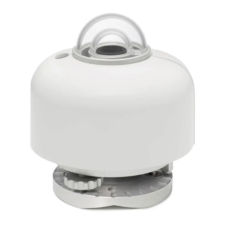
•The new SR30-M2-D1 pyranometer offers improvements over its predecessor SR30-D1.
Already owning SR30(’s)? Please read this memo to benefit from the improvements.
•Need support for SR30-M2-D1? Please consult the user manual on the SR30-M2-D1
product page and, when using the new Hukseflux Sensor Manager software, the user
manual on the Hukseflux Sensor Manager support page.
•Need support for model SR30-D1? It has a separate user manual. Please find it here. Full
support and recalibration services will continue.
•For the latest software and user manuals, please refer to
https://www.hukseflux.com/downloads.
© 2020, Hukseflux Thermal Sensors B.V.
www.hukseflux.com
Hukseflux Thermal Sensors B.V. reserves the right to change specifications without notice.

