Hukseflux IHF02 User manual

IHF02 manual v1907 2/35
Warning statements
Follow the installation instructions of this user
manual.
Putting more than 12 Volt across the sensor wiring
can lead to permanent damage to the sensor.
Do not use “open circuit detection” when measuring
the sensor output.
Do not apply a point load on the sensor.
Twisting the metal sheathed cable might damage it.
Only for supply with the optional CE type
examination (ATEX) certificate: ask the supplier for
ATEX rated operating conditions.

IHF02 manual v1907 3/35
Contents
Warning statements 2
Contents 3
List of symbols 4
Introduction 5
1Ordering and checking at delivery 9
1.1 Ordering IHF02 9
1.2 Included items 9
1.3 Quick instrument check 10
2Instrument principle and theory 11
3Specifications of IHF02 13
3.1 Specifications of IHF02 13
3.2 Dimensions of IHF02 16
4Standards and recommended practices for use 17
4.1 Heat flux measurement in industry 17
5Installation of IHF02 18
5.1 Site selection and installation in industry 18
5.2 Use of the magnet frame 21
5.3 Electrical connection 23
5.4 Requirements for data acquisition / amplification 24
6Maintenance and trouble shooting 25
6.1 Recommended maintenance and quality assurance 25
6.2 Trouble shooting 26
6.3 Calibration and checks in the field 27
7Appendices 29
7.1 Appendix on uncertainty evaluation 29
7.2 Appendix on cable extension / replacement 29
7.3 Appendix on calibration hierarchy 30
7.4 Appendix on black coating 30
7.5 Appendix on correction for temperature dependence 31
7.6 Appendix on measurement range for different temperatures 32
7.7 Appendix on use in (potentially explosive) environments 33
7.8 EU declaration of conformity 34

IHF02 manual v1907 5/35
Introduction
IHF02 ultra sensitive industrial heat flux sensor measures heat flux and temperature,
typically in industrial high-temperature environments. The instrument is waterproof,
withstands high pressures and is extremely robust. IHF02 is 25 times more sensitive
than model IHF01, making it suitable for use at relatively low heat flux levels. It replaces
model HF01 high temperature heat flux sensor. IHF02 complies with industrial safety
standards, such as CE and ATEX for explosive areas, and is particularly suitable for
trend-monitoring and comparative testing.
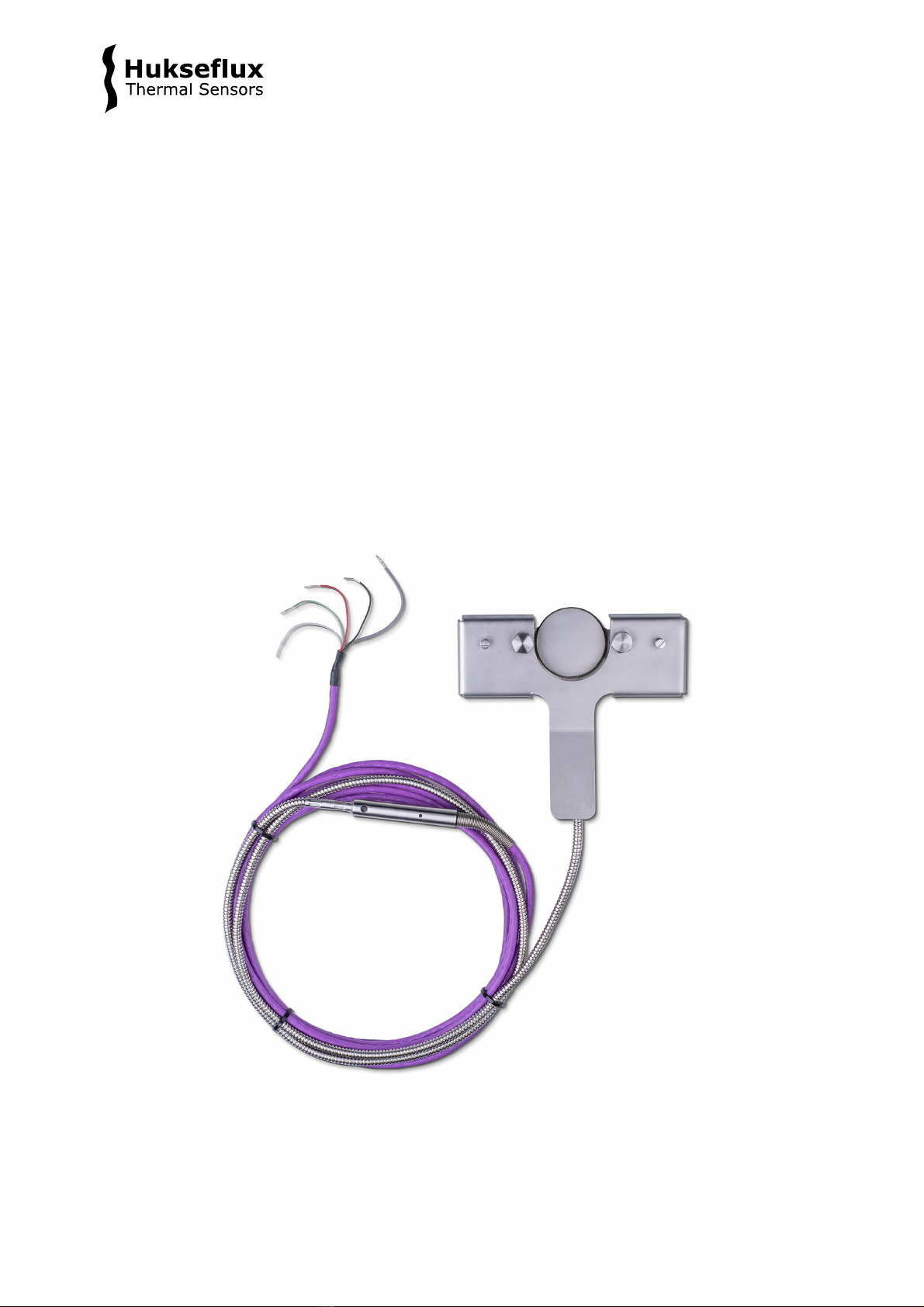
IHF02 measures heat flux and surface temperature of industrial equipment like furnaces,
boilers, fluidised beds, distillation columns and ovens. The sensors inside IHF02, a
thermopile and a type K thermocouple, are protected by a fully sealed stainless steel
body. It is suitable for long-term use at one location as well as surveys at multiple
locations. IHF02 measures heat flux through the object on which it is mounted, in W/m2,
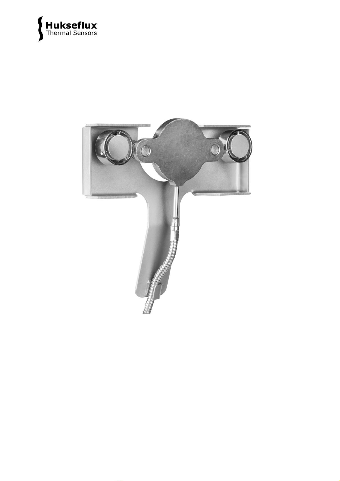
as well as the temperature in °C. An optional magnet frame is offered for easy mounting
on magnetic surfaces.
IHF02 is 25 times more sensitive than model IHF01, so that, with the same
measurement accuracy of its output voltage, it can be used to measure much lower heat
flux levels. When equipped with the optional magnet frame and optional black coating,
IHF02 replaces model HF01 high temperature heat flux sensor.
Figure 0.1 IHF02 ultra sensitive industrial heat flux sensor

IHF02 manual v1907 6/35
The part of the cabling closest to the sensor is a special high-temperature metal sheathed
cable with an interlocked spiral stainless steel armour. The sensor as well as the high-
temperature cable and armour withstand temperatures up to 900 °C. The temperature range
is reduced to 650 °C in case the optional black coating is used. The magnet frame can be
used up to 500 °C. The low-temperature extension cable has a jacket of PTFE type plastic.
Operation
Using IHF02 is easy. It can be connected directly to commonly used data logging
systems. The heat flux, Φ, in W/m2, is calculated by dividing the IHF02 output, a small
voltage U, by the sensitivity S.
The measurement function of IHF02 is:
Φ = U/S (Formula 0.1)
The sensitivity is provided with IHF02 on its product certificate. Equipped with heavy-duty
cabling and a fully stainless steel casing, preventing moisture from penetrating the sensor,
IHF02 has proven to be very reliable. It survives long-term outdoor installation.
Figure 0.3 IHF02 ultra sensitive industrial heat flux sensor with optional magnet frame
seen from above. The part of the cabling closest to the sensor is a special high-temperature
metal sheathed cable with an interlocked spiral stainless steel armour.

IHF02 manual v1907 7/35
IHF02 advantages
•high sensitivity
•robust
•suitable for use at high temperatures
•IP protection class: IP67
•signal wires electrically insulated from the sensor body
Suggested use
trend-monitoring and comparative measurement of heat flux and surface temperature in
industrial installations, such as the shell of aluminium reduction cells.
Figure 0.2 IHF02 industrial heat flux sensor mounted on an object using spring-loaded
bolts (on the left), and with IHF02’s easy-to-use optional magnet frame (on the right).
The instrument is suitable for long-term use at one location as well as for survey purposes at
multiple locations, also outdoor.
Calibration
IHF02 calibration is traceable to international standards. The factory calibration method
follows the recommended practice of ASTM C1130-17. IHF02 is calibrated at room
temperature, mounted on a metal heat sink.
Trend monitoring and comparative measurement
IHF02 is most suitable for relative measurements using one sensor, i.e. monitoring of
trends relative to a certain reference point in time or comparing heat flux at one location
to the heat flux at another location. If the user wants to perform accurate absolute
measurements with IHF02, as opposed to relative measurements, the user must make
his own uncertainty evaluation and correction for systematic errors. See the Appendix on
uncertainty evaluation. However, in many situations the analysis of trends is sufficient.
In that case a high absolute measurement accuracy is not needed, and a formal
uncertainty evaluation is not necessary.

IHF02 manual v1907 8/35
See also
•model IHF01 for an industrial heat flux sensor less sensitive than IHF02, but more
economic
•model HF05 for a heat flux sensor with a high sensitivity at a lower temperature range
•our complete range of heat flux sensors
•our industrial heat flux sensors (PDF)
Figure 0.3 IHF02 with its optional magnet frame for easy mounting on magnetic surfaces

IHF02 manual v1907 9/35
1Ordering and checking at delivery
1.1 Ordering IHF02
The standard configuration of IHF02 is with 1 metre high-temperature cable and 3
metres low-temperature extension cable.
Common options are:
•magnet frame for easy mounting on magnetic surfaces, suitable for survey purposes
as well as for permanent mounting
•black coating
•longer cable (specify total cable length for both cable types in m)
•EC type examination certificate (ATEX) II 2 G EEx d IIC T6
•connector at IHF02 cable end
•extension cable with 2 connectors matching cable connector and chassis connector
(specify cable length in m)
•chassis connector with internal wiring
(colour code of wiring identical to cable colour code)
1.2 Included items
Arriving at the customer, the delivery should include:
•heat flux sensor IHF02
•with cables of the length as ordered
•any other option as ordered
•product certificate matching the instrument serial number
Figure 1.2.1 IHF02 industrial heat flux sensor as delivered in its standard configuration

IHF02 manual v1907 10/35
1.3 Quick instrument check
A quick test of the instrument can be done by connecting it to a multimeter.
1. Check the electrical resistance of the heat flux sensor between the black [-] and red
[+] wires and the thermocouple between the green [+] and white [-] wires. Measure the
sensor resistance first with one polarity, then reverse the polarity. Take the average
value. Compare the results with the resistance values on the product certificate. Infinite
resistance indicates a broken circuit; zero or a lower than 1 Ω resistance indicates a short
circuit.
2. Check if the heat flux sensor reacts to heat: put the multimeter at its most sensitive
range of DC voltage measurement. Expose the sensor to a strong heat source, for
instance using a heat gun. Exposing the side flush with flanges should generate a
positive signal, doing the same at the opposite side, the sign of the output voltage
reverses.
Also look at the reaction of the thermocouple to heat.
3. Inspect the instrument for any damage.
4. Check the sensor serial number engraved on the transition piece against the certificate
provided with the sensor.

IHF02 manual v1907 11/35
2Instrument principle and theory
IHF02’s scientific name is heat flux sensor. A heat flux sensor measures the heat flux
density through the sensor itself. This quantity, expressed in W/m2, is usually called
“heat flux”. IHF02 users typically assume that the measured heat flux is representative
of the undisturbed heat flux at the location of the sensor. Users may also apply
corrections based on scientific judgement.
The heat flux sensor in IHF02 is a thermopile. This thermopile measures the temperature
difference across the stainless steel body of IHF02. Working completely passive, the
thermopile generates a small voltage that is a linear function of this temperature
difference. The heat flux is proportional to the same temperature difference divided by
the effective thermal conductivity of the heat flux sensor body. Using IHF02 is easy. For
readout the user only needs an accurate voltmeter that works in the millivolt range. To
convert the measured voltage, U, to a heat flux Φ, the voltage must be divided by the
sensitivity S, a constant that is supplied with each individual sensor.
The temperature sensor inside IHF02 is a type K thermocouple located at the side of the
sensor flush with the flanges.
Figure 2.1 The general working principle of a heat flux sensor. The sensor inside IHF02
is a thermopile. A thermopile consists of a number of thermocouples, each consisting of
two metal alloys marked 1 and 2, electrically connected in series. A single thermocouple
will generate an output voltage that is proportional to the temperature difference
between its hot- and cold joints. Putting thermocouples in series amplifies the signal. In
a heat flux sensor, the hot- and cold joints are located at the opposite sensor surfaces 4
and 5. In steady state, the heat flux 6 is a linear function of the temperature difference
across the sensor and the average thermal conductivity of the sensor body, 3. The
thermopile generates a voltage output proportional to the heat flux through the sensor.
The exact sensitivity of the sensor is determined at the manufacturer by calibration, and
is found on the calibration certificate that is supplied with each sensor.
5
4
32
1
6

IHF02 manual v1907 12/35
Heat flux sensors such as IHF02, for use in industry, are typically calibrated under the
following reference conditions:
•conductive heat flux (as opposed to radiative or convective heat flux)
•homogeneous heat flux across the sensor
The IHF02 factory calibration procedure uses the following reference conditions:
•instrument temperature of 25 °C
•heat flux of 6 x 10³ W/m2
•mounted on a water-cooled aluminium heatsink
•thermal conductivity of the surrounding environment 0.0 W/(m∙K)
Unique features of IHF02 are:
•high sensitivity, for use at relatively low heat flux levels
•robustness, including a strong cable
•suitable for use at high temperatures, up to +900 °C
•built-in temperature sensor; type K thermocouple
•IP protection class: IP67 (essential for outdoor application)
•sensors isolated from housing
Measuring with heat flux sensors, errors may be caused by differences between
calibration reference conditions and the conditions during use. The user should analyse
his own experiment and make his own uncertainty evaluation.
Figure 2.2 IHF02: the heat flux sensor consists of a stainless steel body (1) which is
connected via a rigid stainless steel coupler (3) to a flexible high-temperature metal
sheathed cable with interlocked spiral stainless steel armour (6). After a transition piece
(4), wires are extended using a low-temperature extension cable (7). In the standard
configuration, the cable ends in bare wires (5). Two mounting flanges (2) are attached to
the body.

IHF02 manual v1907 13/35
3Specifications of IHF02
3.1 Specifications of IHF02
IHF02 measures the heat flux density through the surface of the sensor. This quantity,
expressed in W/m2, is called heat flux. It also measures the instrument body
temperature. IHF02 is passive, using thermopile and thermocouple sensors. The
thermopile generates a small output voltage proportional to the heat flux. IHF02 can only
be used in combination with a suitable measurement system. The sensor should be used
in accordance with the recommended practices of ASTM.
Table 3.1 Specifications of IHF02 (continued on next page)
IHF02 SPECIFICATIONS
Sensor type
industrial heat flux sensor
Sensor type according to ASTM
heat flow sensor or heat flux transducer
Heat flux sensor
thermopile
Measurand
heat flux
Measurand in SI units
heat flux density in W/m2
Measurement range
(-100 to +100) x 10³ W/m2
see appendix on measurement range for different
temperatures
Temperature sensor
thermocouple type K
Temperature sensor specification
EN 60584-1:2013
ASTM E230 / E230M-12
Measurand
temperature
Measurand in SI units
temperature in °C
Measurement function / required
programming
Φ = U/S
Sensitivity range
(200 to 300) x 10-9 V/(W/m2)
Sensitivity (nominal)
250 x 10-9 V/(W/m2)
Temperature dependence
< 0.1 %/°C
Non-stability
< 1 %/yr (for typical use)
Response time (95 %)
210 s (nominal)
Directional sensitivity
heat flux from the side flush with the flanges to the
opposite side generates a positive voltage output signal
Required sensor power
zero (passive sensors)
Expected voltage output
multiply the sensitivity by the maximum expected
heat flux
Required readout
heat flux sensor: 1 x differential voltage channel or 1
x single ended voltage channel
temperature sensor: 1 x Type K differential
thermocouple channel or 1 x Type K single ended
thermocouple channel
both with input resistance > 10
6
Ω
Rated operating temperature range
-30 to +900 °C (sensor and high temperature cable)
-30 to +650 °C (optional black coating)
-30 to +500 °C (optional magnet frame)
-30 to +280 °C (optional magnet frame, permanent
installation) see chapter on use of the
magnet frame
-30 to +240 °C (low temperature extension cable)
IP protection class
IP67
Rated operating relative humidity range
0 to 100 %
.

IHF02 manual v1907 14/35
Table 3.1 Specifications of IHF02 (started on previous page)
Rated operating pressure
10 bar (clamping on transition piece or low
temperature extension cable)
In case of higher process pressure, contact Hukseflux
Maximum load on sensor
1000 kg (homogeneously distributed)
Sensor diameter
40 x 10-3 m
Sensor thickness
6 x 10⁻³ m
Sensor thermal resistance
2.8 x 10⁻³ K/(W/m²)
Sensor thermal conductivity
2.1 W/(m∙K) (average)
Heat flux sensor resistance (nominal)
15 Ω (standard cable lengths)
Temperature sensor resistance (nominal)
35 Ω (standard cable lengths)
Standard cable lengths
High-temperature cable
Low-temperature extension cable
1 m (see options)
3 m (see options)
Low-temperature extension cable:
heat flux sensor cable resistance
0.2 Ω/m (nominal)
High-temperature cable:
heat flux sensor cable resistance
13 Ω/m (nominal)
Low-temperature extension cable:
temperature sensor cable resistance
3 Ω/m (nominal)
High-temperature cable:
temperature sensor cable resistance
28 Ω/m (nominal)
High-temperature cable diameter
5 x 10⁻³ m
Low-temperature extension cable
diameter
4.5 x 10⁻³ m
Transition piece diameter
10 x 10-3 m
Marking
1 x engraving on the transition piece, showing serial
number
Gross weight including 1 and 3 m cable
0.60 kg
Net weight including 1 and 3 m cable
0.25 kg
Packaging
plastic case of 265 x 226 x 50 mm
INSTALLATION AND USE
Typical conditions of use
in measurements in industrial environments. Exposed
to high heat fluxes for periods of several minutes to
several years. Connected to user-supplied data
acquisition equipment. Regular inspection of the
sensor surface and housing. Continuous monitoring of
sensor temperature. No special requirements for
immunity, emission, chemical resistance.
Orientation
the side flush with the flanges must be in contact with
the object on which the sensor is mounted
Installation
see the chapter on installation of IHF02
avoid mechanical force on the flanges, sensor body
and sensor-to-cable transition.
Recommended number of sensors
2 per measurement location
Cable extension
see options: longer cables, extension cable and
connectors
Optional connectors on IHF02 cable and
extension cable
female receptable LEMO PCA.1S.304.CLLC47
male plug LEMO FFA.1S.304.CLAC47
CALIBRATION
Calibration traceability
to SI units
Product certificate
included (showing calibration result and traceability)
Calibration method
method IHFC, according to ASTM C1130-17
Calibration hierarchy
from SI through international standards and through
an internal mathematical procedure
Calibration uncertainty
± 10 % (k = 2)
.

IHF02 manual v1907 15/35
Table 3.1 Specifications of IHF02 (started on previous 2 pages)
Recommended recalibration interval
2 years
Calibration reference conditions
25 °C, heat flux of 6 x 10³ W/m2, mounted on a water-
cooled aluminium heat sink, thermal conductivity of the
surrounding environment 0.0 W/(m·K)
Validity of calibration
based on experience the instrument sensitivity will not
change during storage. During use the instrument
“non-stability” specification is applicable.
Field calibration
is possible by comparison to a calibration reference
sensor. Usually mounted side by side. Preferably
reference and field sensor of the same model and
brand. Typical duration of test > 24 h.
Temperature sensor tolerance class
IEC 60584-1:2013: type K, tolerance class 1
Temperature sensor error limits
according to IEC 60584-1: 2013 or ASTM E230 /
E230M -12
MEASUREMENT ACCURACY
Uncertainty of the measurement
statements about the overall measurement
uncertainty can only be made on an individual basis.
see the chapter on uncertainty evaluation.
VERSIONS / OPTIONS
Order code
IHF02 - cable length high temperature in m - cable
length low temperature extension cable in m
Magnet frame
practical magnet frame for easy mounting on
magnetic surfaces, in surveys and for permanent
mounting (add -MF to order code)
With black coating
top side of sensor coated black (add -BC to order code)
see appendix on black coating
Longer cables
longer cables (specify total cable length for both cable
types in m)
EC type examination certificate (ATEX)
II 2 G EEx d IIC T6
Extension cable
extension cable with 2 connectors matching cable
connector and chassis connector
(specify cable length in m)
Connector
connector at IHF02 cable end
Chassis connector
chassis connector with internal wiring
(colour code of wiring identical to cable colour code)

IHF02 manual v1907 17/35
4Standards and recommended practices
for use
IHF02 should be used in accordance with the recommendations of this user manual.
See the typical conditions of use in the specifications chapter; discuss any deviations.
4.1 Heat flux measurement in industry
Many IHF02 sensors measure on industrial walls and metal surfaces, estimating the
installation’s energy balance and the thermal transmission of walls. Typically, the total
measuring system consists of multiple heat flux- and temperature sensors. In many
cases heat flux sensors are used for trend-monitoring. In such cases reproducibility is
more important than absolute measurement accuracy.
Figure 4.1.1 Example of an IHF02 industrial heat flux sensor mounted on an object to
be measured using spring-loaded bolts. The sensor is mounted on a well prepared flat
surface.

IHF02 manual v1907 18/35
5Installation of IHF02
5.1 Site selection and installation in industry
Table 5.1.1 Recommendations for installation of IHF02 heat flux sensors
Location
choose a location that is representative of the process that is analysed.
if possible, avoid exposure to sun, rain, etc.
do not expose to drafts and lateral heat fluxes.
do not mount in the vicinity of thermal bridges, cracks, heating or cooling
devices and fans.
Performing a
representative
measurement /
recommended
number of sensors
we recommend using > 2 sensors per measurement location.
This redundancy also improves the assessment of the measurement
accuracy.
Orientation
mount with the flanges flush with the object, see Figure 5.1.2. and 5.1.3.
mounted on vertical surfaces, the cable exit from the sensor should point
down.
Surface cleaning and
levelling
create a clean and smooth surface with a diameter of 70 x 10-3 m, so that
the air gap between sensor and object surface is less than 0.2 x 10⁻³ m.
Mechanical mounting:
using the mounting
flanges
the sensor body withstands only limited pressure and strain.
users should not exert significant mechanical force on the flanges.
tack-weld M6 thread to the surface on which IHF02 is mounted at a
centre-to-centre distance of 55 x 10-3 m and fix the sensor with a nut.
Alternatively, use M6 bolts to screw the sensor directly in the surface.
bolts and nuts holding the sensor should be used for positioning and for
loose fixation only, and should be spring- loaded to guarantee good
sensor-to-surface contact without exerting too much force.
Mechanical mounting:
clamping
clamp on the transition piece or low temperature extension cable using a
compression fitting.
Use of the magnet
frame
see the paragraph on use of the magnet frame.
Permanent
installation
for long-term installation, fill up the space between sensor and object, for
example with high-temperature thread paste (Molykote P37 thread paste,
specified rated to 1400 °C) or with a graphite packing material
(Egraflex GTC 0.3 mm thickness rated to 450 °C). Use this in
combination with the spring-loaded threads. We discourage the use of
thermal paste because it tends to dry out.
Signal amplification
see the paragraph on electrical connection.
Mounting in high
pressure environment
use a sealed compression fitting, either around the transition piece or
around the low temperature extension cable.

IHF02 manual v1907 19/35
Figure 5.1.1 IHF02 showing its two flanges allowing installation on tack-welded M6
threads or with spring-loaded bolts (not included with IHF02). IHF02 should be mounted
on a well-prepared flat surface
Following the recommendations for installation of IHF02 heat flux sensors, there are
three ways to mount the sensor on the object to be measured. The best method depends
on the conditions of your measurement.
•Tack-weld M6 thread to the surface and fix the sensor with a nut. See Figure 5.1.2;
•Alternatively, use M6 bolts to screw the sensor directly into the surface. See Figure 5.1.3;
•Alternatively, use the optional magnet frame for easy mounting on magnetic surfaces.
See next chapter on use of the magnet frame.
Figure 5.1.2 Installation of IHF02 on tack-welded threads
(1) M6 thread
(2) spring-loaded M6 nut
(3) spring
(4) tack-weld
(5) IHF02 side of object to be measured, flush with flanges
(6) heat flux generating positive signal
(7) for long-term installation, apply high-temperature thread paste or a graphite packing
material
(8) mounting flange
2
4
3
1
5 6 7 8

IHF02 manual v1907 20/35
Figure 5.1.3Installation of IHF02 using spring-loaded bolts
(1) spring-loaded M6 bolt
(2) spring
(3) IHF02 side of object to be measured, flush with flanges
(4) heat flux generating positive signal
(5) for long-term installation, apply high-temperature thread paste or a graphite packing
material
(6) mounting flange
(7) for long-term installation, use threadlocking
1
7
2
3456
This manual suits for next models
2
Table of contents
Other Hukseflux Accessories manuals

Hukseflux
Hukseflux SR30-M2-D1 User manual

Hukseflux
Hukseflux TP01 User manual

Hukseflux
Hukseflux STP01 User manual

Hukseflux
Hukseflux FHF04SC User manual

Hukseflux
Hukseflux HF01 User manual

Hukseflux
Hukseflux HFP01 User manual

Hukseflux
Hukseflux SR30-M2-D1 User manual

Hukseflux
Hukseflux FHF05 Series User manual

Hukseflux
Hukseflux BLK Series User manual

Hukseflux
Hukseflux FHF05SC Series User manual