Hukseflux TP01 User manual

Copyright by Hukseflux | manual v1627 | www.hukseflux.com | info@hukseflux.com
USER MANUALTP01
Thermal properties sensor
Hukseflux
Thermal Sensors

TP01 manual v1627 2/35
Warning statements
Putting more than 2 Volt across the sensor wiring
can lead to permanent damage to the sensor.
Putting more than 2 Volt across the heater wiring
can lead to permanent damage to the heater.
Do not use “open circuit detection” when measuring
the sensor output.
If power to the heater is supplied from a 12 VDC
source, you must put a 150 Ω resistor in series with
the heater.

TP01 manual v1627 3/35
Contents
Warning statements 2
Contents 3
List of symbols 4
Introduction 5
1Ordering and checking at delivery 8
1.1 Ordering TP01 8
1.2 Included items 8
1.3 Quick instrument check 8
2Instrument principle and theory 9
2.1 General theory 9
2.2 Thermal conductivity measurement 10
2.3 Soil thermal conductivity for several soil types 11
2.4 Thermal diffusivity measurement 11
2.5 Volumic heat capacity measurement 12
2.6 Measuring the storage term in soil heat flux measurement 12
2.7 Trend monitoring of soil water content 13
2.8 Calibration 13
2.9 Programming 14
3Specifications of TP01 16
3.1 Dimensions of TP01 19
4Standards and recommended practices for use 20
5Installation of TP01 21
5.1 Site selection and installation 21
5.2 Electrical connection 22
5.3 Requirements for data acquisition / amplification 24
6Making a dependable measurement 25
6.1 Uncertainty evaluation 25
6.2 Typical measurement uncertainties 25
6.3 Contributions to the uncertainty budget 26
7Maintenance and trouble shooting 28
7.1 Recommended maintenance and quality assurance 28
7.2 Trouble shooting 29
7.3 TP01 calibration 30
8Appendices 32
8.1 Appendix on cable extension / replacement 32
8.2 Appendix on preparation of agar gel for calibration 32
8.3 Appendix on use of TP01 beyond its rated measurement range 33
8.4 EU declaration of conformity 34

TP01 manual v1627 4/35
List of symbols
Quantities Symbol Unit
Thermal conductivity λW/(m∙K)
Voltage output U V
Voltage output as a function of heating time U (t) V
Voltage output difference ΔU V
Sensitivity S V/K
Heating power per meter Q W/m
Heater length L m
Temperature T °C
Temperature difference ΔT °C, K
Time constant τs
Time t s
Volumic heat capacity cvolumic J/(m³∙K)
Resistance R Ω
Storage term S W/m²
Depth of installation x m
Water content (on mass basis) θmkg/kg
Water content (on volume basis) θvm³/m³
Subscripts
property of thermopile sensor sensor
property obtained under calibration reference reference
conditions
property at the (soil) surface surface
property of the surrounding soil soil
property of the heater heater

TP01 manual v1627 5/35
Introduction
TP01 is a sensor for long-term monitoring of soil thermal conductivity. A measurement
with TP01 may also be used to estimate the soil thermal diffusivity and volumic heat
capacity, leading to a better understanding of dynamic (variable heat flux) thermal
behaviour of soils. TP01 is designed for long-term use at one measurement location.
Applied in meteorological surface flux measurement systems, TP01 improves the
estimates of soil heat flux and of the so-called storage term (see the paragraph about
the storage term). The sensor, combining a heater and a temperature-difference sensor
with a high sensitivity and an extremely low thermal mass, is a proprietary Hukseflux
design.
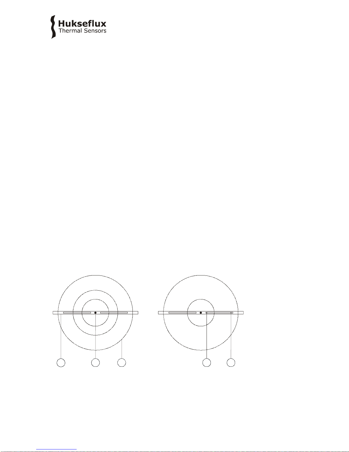
The sensor inside TP01 is a temperature-difference sensor consisting of 2 thermopiles. It
measures the radial temperature difference around a heating wire with a record breaking
sensitivity. Both the heating wire and the sensor are incorporated in a very thin plastic
foil.
TP01 measures soil thermal conductivity. It is designed for long-term on-site operation,
buried in the soil. Its rated operating range is 0.3 to 4 W/(m∙K), which covers most
inorganic soil types. The low thermal mass of TP01 also makes it suitable for measuring
the soil thermal diffusivity and the volumic heat capacity.
The thermal conductivity, λ, in W/(m·K), is calculated by dividing the TP01 sensitivity, S,
by the sensor output, a small voltage difference ΔU which is a response to stepwise
heating, and multiplying by the applied electrical power Q per meter heating wire.
The measurement function of TP01 is:
λ = S·Q/ ΔU (Formula 0.1)
The factory-determined sensitivity S,as obtained under calibration reference conditions,
is provided with TP01 on its product certificate. TP01 calibration is traceable to
international standards. The recommended calibration interval of TP01 is 2 years.
Thermal diffusivity and volumic heat capacity are estimated from time response to
stepwise heating. These measurements are optional.
The volumic heat capacity is a linear function of soil water content and you may use TP01
measurements to monitor trends in soil water content. Contrary to many other soil water
content sensors, TP01 is not sensitive to contamination by salts and the measurement
still functions in electrically conducting saline or fertilised soils.
TP01 should be incorporated in the user's measurement and control system. It can be
connected directly to commonly used data logging systems. Typically every 6 hours, the
TP01 heater is switched on to perform a measurement.
A typical TP01 is part of a meteorological surface flux measurement system in which also
wind, humidity, soil heat flux, soil temperatures at different depths and net-radiation are

TP01 manual v1627 6/35
measured. TP01 then serves to improve the estimate of the so-called storage term,
which is used to model thermal heat transport in the soil. Measurements with TP01 are
often combined with soil temperature profile measurements with sensor model STP01
and measurements with heat flux sensor model HFP01SC.
Soil thermal properties change as a function of depth, in particular close to the soil
surface. A typical measurement location is equipped with sensors at several depths. For
good spatial averaging at least 2 sensors (> 5 m apart) should be installed at every
depth.
Hukseflux has equipped several testbeds in the electrical power industry, to monitor
dryout, thermal runaway and thermal stability around mock-up high-voltage power lines.
Here the capability to perform a measurement of thermal diffusivity is an important
feature for modelling behaviour under dynamic loads.
Equipped with heavy duty cabling, and potted so that moisture does not penetrate the
sensor, TP01 has proven to be very robust and stable. It survives long-term installation
in soils.
Figure 0.1 TP01. Standard cable length is 5 m.

TP01 manual v1627 7/35
See also:
•STP01 soil temperature profile sensor
•for laboratory use, models TP02 and TP08 are available. Turn key measuring systems
are TPSYS02, FTN02 and MTN02.
•Hukseflux sensors for surface flux measurement
•heat flux sensors HFP01 and HFP01SC
Figure 0.2 TP01 thermal properties sensor. The thermopile sensor (1) and heating wire
(2) are both incorporated in a thin plastic foil. The cable (3) is 5 m long in the standard
configuration and may be extended to 50 m.
20
4
20 60
1
31.
2.
3.
4.
5.
6.
0.15

TP01 manual v1627 8/35
1Ordering and checking at delivery
1.1 Ordering TP01
The standard configuration of TP01 is with 5 metres cable.
Common options are:
•longer cable in multiples of 5 m, cable lengths above 20 m in multiples of 10 m.
specify total cable length.
1.2 Included items
Arriving at the customer, the delivery should include:
•thermal properties sensor TP01
•cable of the length as ordered
•product certificate matching the instrument serial number
1.3 Quick instrument check
A quick test of the instrument can be done by connecting it to a multimeter.
1. Check the electrical resistance of the sensor and heater according to table 5.2.2. Use a
multimeter at the 100 Ω range. The typical resistance of the wiring is 0.1 Ω/m (added
value of 2 wires). Infinite resistance indicates a broken circuit; zero or a lower than 1 Ω
resistance indicates a short circuit.
2. Check if the sensor reacts to heat: put the multimeter at its most sensitive range of
DC voltage measurement, typically the 100 x 10-3 VDC range or lower. Activate the TP01
heater by putting 1 to 2 VDC across the brown and yellow wires. Use a 1.5 V battery. Put
the sensor in soil or another granular material. The signal between the green and white
output should read > 1 x 10⁻³ V now. It will vary if the sensor moves.
3. Inspect the instrument for any damage.
4. Check the sensor serial number, and sensitivity on the cable labels (one at sensor end,
one at cable end) against the product certificate provided with the sensor.

TP01 manual v1627 9/35
2Instrument principle and theory
TP01 measures the thermal conductivity [λ] of the surrounding environment. It has a
rated measurement range of 0.3 to 5 W/(m·K) which makes it suitable for use in most
soils. A requirement for an accurate measurement is that there is good thermal contact
between soil and sensor. You must incorporate TP01 in your own measurement and
control system. For thermal conductivity measurement this system should perform 2 x
voltage readout, and power supply switching. For thermal diffusivity and volumic heat
capacity the sensor response time must be measured.
Advantages of using TP01 are:
•high sensitivity (good signal to noise ratio in low-flux environments, low use of
power)
•low thermal mass (allows for a quick measurement and the ability to measure
thermal diffusivity and heat capacity)
•robustness, including a strong cable (essential for permanently installed sensors)
•IP protection class: IP67 (essential for outdoor application)
•low electrical resistance (low pickup of electrical noise)
2.1 General theory
The thermopile sensor generates a voltage output, as a reaction to the radial
temperature difference around the heating wire. This can be seen in figure 2.1.1. It gives
a top view of the sensor and the surrounding soil when heating. The heating wire
generates a circular temperature field. After 180 s, the temperature difference around
the sensor becomes stable.
Figure 2.1.1 Top view of the radial temperature distribution (with isotherms (3)) around
the heating (2) wire of TP01 (1) in two different environments; right high thermal
conductivity, left low thermal conductivity. The thermopiles measure the difference
between the temperature at the hot joints (4) and the cold joints (5).
T
3
T
2
T
1
T
2
T
1
2
13 4 5
λ >>λ <<

TP01 manual v1627 10/35
U
t
U ~ 1/λ
t ~ a
λ< λ1 1
, a > a
λ=λ1 1
, a < a
λ>λ1 1
, a = a
Figure 2.1.2 TP01 signal in different soil types: the signal amplitude varies with [1/λ],
the response time varies with thermal diffusivity [a]
2.2 Thermal conductivity measurement
The measurement principle of TP01 relies on measurement of the radial temperature
difference around a heating wire. The temperature difference is measured by two
thermopiles connected in series, generating a single output. Both the heater and the
thermopile are incorporated in a thin plastic foil.
The thermal conductivity, λ, in W/(m·K), is calculated by dividing the TP01 sensitivity, S,
by the output, a small voltage difference ΔU which is a response to stepwise heating, and
multiplying by the applied electrical power Q per meter heating wire.
The measurement function of TP01 is:
λ = S·Q/ ΔU(Formula 0.1)
The voltage difference ΔU is determined by performing a measurement just before the
heating starts and after heating for 180 s.
ΔU = U (180) – U (0) (Formula 2.2.1)
The factory-determined sensitivity S,as obtained under calibration reference conditions,
is provided with TP01 on its product certificate. The heating power Q, in W/m, is
determined from a voltage measurement across the heater and taking the heater length
and electrical resistance into account.

TP01 manual v1627 11/35
2.3 Soil thermal conductivity for several soil types
Data for the following graph is taken from IEEE standard 442 – IEEE guide for Soil
Thermal Resistivity Measurements”, figure 3. It gives orders of magnitude of the thermal
conductivity for different soil types as a function of water content.
Figure 2.3.1 Typical soil thermal conductivity values for different soil types as a function
of water content.
2.4 Thermal diffusivity measurement
The low thermal mass of the total TP01 sensor makes it suitable for estimating thermal
diffusivity [a]. Dividing [λ] by the thermal diffusivity [a] gives the volumic heat capacity
[cvolumic] which varies with water content.
Thermal diffusivity and volumic heat capacity may be estimated from the response time
to stepwise heating.
The output response of TP01 to stepwise heating is:
ΔU = (S·Q/ λ) · F[a·t] (Formula 2.4.1)
With [t] time, [a] thermal diffusivity, and F a function that equals 1 at large values of
[a·t] and 0 at the start of the heating interval.
Formula 2.4.1 shows that the step response of the sensor signal scales with [Q/ λ] for
the amplitude, and with [a] for the time response.

TP01 manual v1627 12/35
By curve fitting F you can determine [a]. One of the easiest ways of doing this is looking
at the 63 % response time of the measurement. The common procedure is to first
determine the thermal conductivity, and during the settling interval after the heating
interval to determine how much time it takes to arrive at 37 % of the ΔU amplitude.
The thermal diffusivity is measured by comparing the TP01 response time during the
measurement to that under calibration reference conditions. The calibration reference
conditions include a thermal diffusivity of 0.14 10-6 m2/s.
a reference = 0.14 10-6
The 63 % response time for the determination of the thermal diffusivity is 19 s.
τreference = 19
The measurement equation for the thermal diffusivity is:
a = a reference · τreference / τ (Formula 2.4.2)
2.5 Volumic heat capacity measurement
The volumic heat capacity is determined from
cvolumic = λ/a (Formula 2.5.1)
2.6 Measuring the storage term in soil heat flux measurement
In meteorological experiments one of the measured parameters is heat flux in the soil.
For practical reasons this is done at 0.05 m depth. There is no simple solution for direct
measurement of soil heat flux at the soil surface, which is the parameter that must
eventually be estimated.
The flux at the soil surface Φsurface is usually estimated from the flux measured by the
heat flux sensor buried at a depth of around 0.05 m plus the change of the energy stored
in the layer above the sensor during the measuring interval t1 to t2.
Φsurface = Φ0.05 m + S (Formula 2.6.1)
The quantity S is called the storage term.
The storage term is calculated from a space-averaged soil temperature measurement,
using multiple soil temperature sensors, and an estimate of the volumic heat capacity
cvolumic of the soil above the sensor.
S = (T(t1) - T(t2))·cvolumic·x/(t1 - t2) (Formula 2.6.2)
Where T(t1) - T(t2) is the temperature difference in the measurement interval, x the
depth of installation of the soil heat flux sensors.

TP01 manual v1627 13/35
A correct estimate of Φsurface with a high time resolution requires a low depth of
installation and a correct estimate of the storage term.
At an installation depth of 0.05 m, the storage term typically represents up to 50 % of
the total Φsurface. When the temperature T is measured closely below the surface, the
response time of the storage term to a changing Φsurface is in the order of magnitude of
20 min, while the heat flux sensor buried at twice the depth is a factor 5 slower (square
of the depth). The volumic heat capacity is estimated from the specific heat capacity of
dry soil, csoil, dry, the bulk density of the dry soil ρ, the water content on mass basis Q, on
a volume basis Qv, and cwater, the specific heat capacity of water.
cvolumic = ρsoil·(csoil, dry + θm·cwater) = ρsoil·csoil, dry + ρwater· θv·cwater (Formula 2.6.3)
The heat capacity of water is known, but the other quantities of the equation are difficult
to determine and vary with location and time. The storage term may be the main source
of uncertainty in the soil energy balance measurement.
With TP01 the estimate of the volumic heat capacity is much simpler:
cvolumic = λ/a (Formula 2.5.1)
2.7 Trend monitoring of soil water content
In a certain soil type there are direct and linear relationships between the soil water
content by mass or volume and the volumic heat capacity. TP01 can therefore be used to
monitor trends of soil water content even without detailed knowledge of soil dry densities
and heat capacities.
θm= ((cvolumic / ρsoil )- csoil, dry )) / cwater (Formula 2.7.1)
For estimates on a volume basis, one has to multiply by ρsoil and divide by ρwater:
θv= (cvolumic - csoil, dry ρsoil) / ρwater cwater (Formula 2.7.2)
2.8 Calibration
TP01 factory calibration is traceable from SI.
TP01 is calibrated by a thermal conductivity measurement in a calibration reference
material, and by performing an electrical resistance measurement.
The test method is not standardised. The calibration reference material is a verified
intrinsic measurement standard (vocabulary according to ISO Guide 99), an agar gel,
which has thermal properties similar to water. The agar gel is characterised by a
reference thermal needle, which is traceable to length and electrical resistance. The TP01
heater electrical resistance is traceable to current and voltage standards.

TP01 manual v1627 14/35
2.9 Programming
Soil conditions typically change slowly. A typical time between measurements is 6 hr.
You may choose to shorten the interval between measurements to 3 hr.
2.9.1 Programming for thermal conductivity measurement
λ = S·Q/ ΔU (Formula 0.1)
The power Q in W/m can be determined from the voltage across the heater Uheater and
the heater resistance
λ = S·Uheater2/ (ΔU·R·L) (Formula 2.9.1.1)
With S the sensitivity, R the heater electrical resistance and L the heater length. These
parameters can be found on TP01’s calibration certificate. For the standard model TP01,
the heater length L is 0.06 m, and the heating time interval is 180 s, so that the
measurement equation becomes
λ= S·Uheater2/ (0.06 (U (180) – U (0))·R) (Formula 2.9.1.2)
You may define an acceptance interval for λ, and for Uheater.
2.9.2 Programming for thermal diffusivity measurement
By curve fitting F you can determine [a]. One of the easiest ways of doing this is looking
at the 63 % response time of the measurement. The common procedure is to first
determine the thermal conductivity, and during the settling interval after the heating
interval to determine how much time it takes to arrive at 37 % of the ΔU amplitude.
The measurement equation for the thermal diffusivity is:
a = a reference · τreference / τ (Formula 2.4.2)
= (0.14 x 10-6) ·19/ τ
= 7.4 x 10⁻³/ τ
For a reasonably accurate estimate of the thermal diffusivity, the data storage interval
must be < 1 s.
2.9.3 Programming for the volumic heat capacity measurement
cvolumic = λ/a (Formula 2.5.1)

TP01 manual v1627 15/35
2.9.4 Program summary
In case the user writes his own software program for controlling the TP01, the program
flow in table 2.9.4.1 may be used.
Use a < 1 s data storage interval when the thermal diffusivity is measured.
Table 2.9.4.1 A summary of a program for control of the measurement with TP01
initialisation enter sensor and system
information
serial number, S, R, L, a reference , τreference
every 6 h
360 s thermal
conductivity and thermal
diffusivity measurement
measure U, U
heater,
t
180 s heating interval
heater on
measure U
measure Uheater
180 s settling interval
heater off
measure U
thermal
calculate λ
calculate a
quality checks
acceptance interval λ
acceptance interval a
acceptance interval Uheater
Acceptance interval U(0) – U(180)
if accepted, then
next loop
else
generate warning
calculate derived
parameters such as θ

TP01 manual v1627 16/35
3Specifications of TP01
TP01 measures the thermal conductivity [λ] of its surrounding environment. It is
designed for long-term monitoring of soils. It has a rated measurement range of 0.3 to 5
W/(m·K) which makes it suitable for use in most (inorganic) soils. It is also used for
measurement of thermal diffusivity and volumic heat capacity. Good thermal contact
between soil and sensor is required. TP01 can only be used in combination with a
suitable measurement and control system.
Table 3.1 Specifications of TP01 (continued on next page)
TP01 SPECIFICATIONS
Sensor type
thermal properties sensor
Measurand
thermal conductivity
Rated operating environment surrounded by soil
non-organic, saline and non-saline, fertilised and non-
fertilised soils
Measurand in SI units
thermal conductivity in W/(m·K)
Measurement range
0.3 to 5 W/(m·K)
Optional non-traceable measurand
thermal diffusivity
Measurand in SI units
thermal diffusivity in m2/s)
Measurement range
(0.05 to 1 ) x 10-6 m2/s
Optional non-traceable measurand
volumic heat capacity
Measurand in SI units
volumic heat capacity in J/(kg·K)
Optional trend monitoring
soil water content
Measurand in SI units
water content in kg/kg or m3/m3
Measurement principle radial temperature difference measurement around a
heating wire using a thermopile sensor
Sensitivity
150 x 10-6 V/K (nominal)
Expected voltage output -1 to 1 x 10
-3
V (thermopile sensor)
0 to 1.5 VDC (heater)
Required programming
measurement of thermal conductivity
optionally measurement of thermal diffusivity and
volumic heat capacity
Measurement function / required
programming
λ = S·Q/ ΔU
Optional measurement function/ optional
programming
a = a reference · τreference / τ
Optional measurement function/ optional
programming
c
volumic
= λ/a
Required readout and control thermopile sensor and heater: 2 x differential voltage
channel or 2 x single ended voltage channel,
input resistance > 106Ω
heater: 1 x switchable power 1 - 2 VDC
Required uncertainty 10 x 10
-6
V at 10
-3
V
5 x 10
-3
V at 2 V
Rated operating temperature range
-30 to +80 °C
Temperature dependence < 0.1 %/°C
Time constant in agar gel calibration
reference material 19 s
(nominal)
Non-stability
< 1 %/yr

TP01 manual v1627 17/35
Table 3.1 Specifications of TP01 (started on previous page, continued on next page)
Sensor foil surface dimensions
(60 x 20) x 10-3 m
Sensor foil thickness
0.15 x 10⁻³ m
Connector block dimensions
(43 x 24 x 10) x 10-3 m
Thermopile sensor number of
thermocouple pairs
40
Thermopile sensor resistance range
20 to 50 Ω
Standard governing use of the
instrument
not applicable
Standard cable length (see options)
5 m
Wiring
0.15 m wires and shield at cable ends
Cable diameter
5 x 10⁻³ m
Cable markers
2 x sticker, 1 x at sensor and 1 x cable end, wrapped
around the sensor cable. Both stickers show serial
number.
IP protection class
IP67
Rated operating relative humidity range
0 to 100 %
Gross weight including 5 m cable
0.5 kg
Net weight including 5 m cable
0.4 kg
Packaging
box of 220 x 160 x 30 mm
HEATER
Heater resistance (nominal) 15 Ω
(measured value supplied with each sensor in the
production report)
Heater resistance range
10 to 20 Ω
Heater length
0.06 m
Heater rated power supply
1 to 2 VDC , 0.4 A
Heater power supply
1 VDC (nominal)
Power consumption during heating
interval 0.9 W
(heater powered from 12 VDC, using a 150 Ω series
resistor)
Suggested series resistor
when
powered from 12 VDC
150 Ω ± 5 %, 2 W in series with the heater
Limiting heating power
0.8 W/m
MEASUREMENT
Power consumption daily average 0.007 W
(heater powered from 12 VDC, using a 150 Ω series
resistor, at a 6 hr measurement interval)
Interval between measurements
6 hr, optionally 3 or 12 hr
Duration of measurement
360 s
Heating interval duration
180 s
Settling interval duration
180 s
INSTALLATION AND USE
Measurement depth
0 to 20 m
Recommended number of sensors at a measurement site, at every required
measurement depth use > 2 sensors at a distance of
> 5 m
Orientation recommended orientation is with foil surface vertically
oriented (usually this is perpendicular to the soil
surface), so that flow of water is not obstructed.
Installation
see recommendations in the product manual
Cable extension see chapter on cable extension or order sensors with
longer cable

TP01 manual v1627 18/35
Table 3.1 Specifications of TP01 (started on previous pages)
CALIBRATION
Calibration traceability
to SI units
Production certificate included
(showing calibration result and traceability, as well as
heater resistance and heater length)
Factory calibration method
method TPSC
Factory calibration uncertainty
10 % (k = 2)
Recommended recalibration interval
2 years
Factory calibration reference conditions 20 °C, thermal conductivity of the surrounding
environment 0.6 W/(m·K)
Validity of calibration
based on experience the instrument sensitivity will not
change during storage. During use the instrument
“non-stability” specification is applicable.
Calibration reference material
agar gel, which has thermal properties identical to
those of water:
thermal conductivity of 0.6 W/(m·K)
thermal diffusivity of 0.14 x 10⁻⁶ m2/s
both at 20 °C
MEASUREMENT ACCURACY
Uncertainty of the measurement statements about the overall measurement
uncertainty can only be made on an individual basis.
see the chapter on uncertainty evaluation.
VERSIONS / OPTIONS
Order code
TP01/cable length in m
Longer cable
in multiples of 5 m, cable lengths above 20 m in
multiples of 10 m
option code = total cable length
ACCESSORIES
No accessories

TP01 manual v1627 19/35
3.1 Dimensions of TP01
Figure 3.1.1 TP01 thermal properties sensor.dimensions in x 10-3 m.
(1) thermopile sensor
(2) heating wire
(3) cable (standard length 5 m, optionally longer cable in multiples of 5 m, cable above
20 m in multiples of 10 m)
20
4
20 60
1
31.
2.
3.
4.
5.
6.
0.15

TP01 manual v1627 20/35
4Standards and recommended practices
for use
TP01 sensors are used to measure heat flux in soils, as part of meteorological surface
flux measuring systems. Typically the total measuring system consists of multiple heat
flux- and temperature sensors, often combined with measurements of air temperature,
humidity, solar- or net radiation and wind speed.
There are no standardised operating practices for use of TP01 sensors. The next chapters
contain recommendations of the sensor manufacturer.
In meteorological applications a thermal properties sensor measures thermal conductivity
and volumic heat capacity of the soil, typically at several depths.
Usually this measurement is combined with measurements of the soil temperature to
estimate the heat flux at the soil surface. Knowing the heat flux at the soil surface, it is
possible to “close the balance" and estimate the uncertainty of the measurement of the
other (convective and evaporative) fluxes.
Figure 4.1 Typical meteorological surface energy balance measurement system with
TP01 installed under the soil.
Table of contents
Other Hukseflux Accessories manuals

Hukseflux
Hukseflux FHF05SC Series User manual

Hukseflux
Hukseflux FHF05 Series User manual

Hukseflux
Hukseflux STP01 User manual

Hukseflux
Hukseflux FHF03 User manual

Hukseflux
Hukseflux HFP01 User manual

Hukseflux
Hukseflux LP02 User manual

Hukseflux
Hukseflux SR30-M2-D1 User manual

Hukseflux
Hukseflux IHF02 User manual

Hukseflux
Hukseflux HF01 User manual

Hukseflux
Hukseflux FHF04SC User manual
Popular Accessories manuals by other brands

Mountain Buggy
Mountain Buggy carrycot plus instructions

SLOC
SLOC SPR-203 Initial setup

INNOLIVING
INNOLIVING INN-064 user manual

Dorner
Dorner iDrive 3200 Series Installation, maintenance & parts manual

OUTXE
OUTXE PCPB20000WS user manual

Louroe Electronics
Louroe Electronics AP-8TB Installation and operating instructions