7
Metal Enclosure Installation
9. Leave sucient slack in the antenna cables to allow the door to open and
close without crimping.
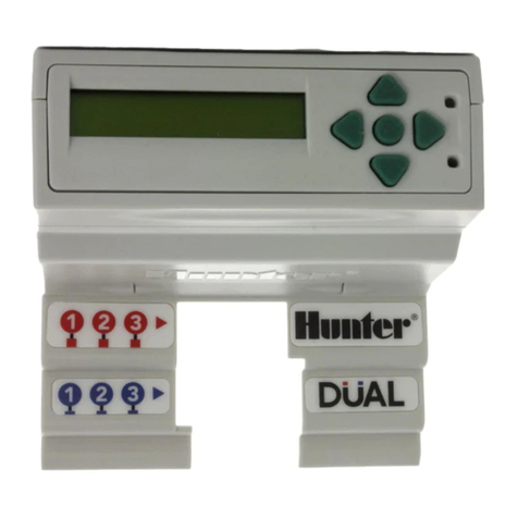
10. Insert the Com module into the opening where the logo cover was with
the display and buttons protruding through the opening. Secure with
screws on each corner.
11. Carefully insert the modular ribbon connector plug from the Com module
into the mating receptacle in the door frame. This connector is keyed and
has slots that must be aligned correctly, so that the connector can only
t one way. The ribbon cable can be extended or shortened slightly by
pushing it back into the com module slot. Press rmly to make sure the
connector is fully seated.
Radio Connections, Additional Steps
• Before installing the radio module, connect the DB-15 connector from the
ribbon cable to the top of the radio and secure with the connector screws
(do not overtighten).
• Connect the radio power cable from the radio to the radio power
connection on the bottom of the Com module.
• Connect the male BNC radio antenna connector to the AIM-BNC before
installing the radio into the radio compartment.
• Install the radio into the radio compartment (see radio installation
instructions for additional information).
• Connect the AIM-BNC to the antenna cable.
Reapply controller power. Verify that the Com module display lights up and
displays characters.
If there is no display:
1. Double-check ribbon cable connection from Com module to facepack
door frame receptacle.
2. Double-check ribbon cable from facepack door frame to controller
cabinet.
Radio Installation, Additional Steps
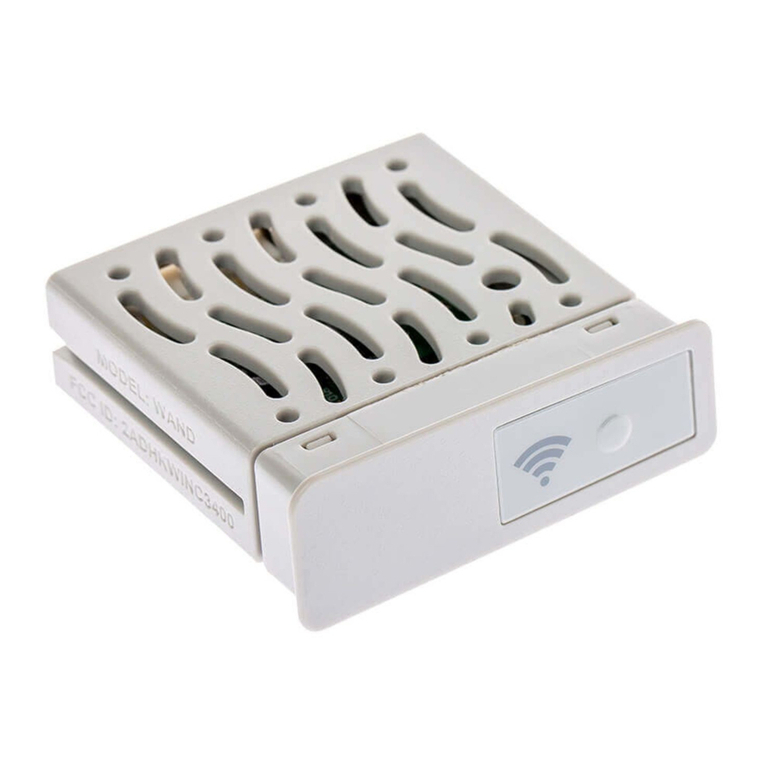
• If radio communications will be used, connect the RAD3 radio module
cables to the Com module with its ribbon cable and power connector rst.
• Install the Com module into the bracket. Then install the radio on the
APPBRKT2 with supplied hardware.
• Install IMMS-ANT-2 in pedestal lid.
• Route antenna cable from the IMMS-ANT-2 through the hole in the top of
the pedestal frame, down into the controller to the radio location.
• Connect the cable connector to the radio module (be sure to turn the
BNC connector until it locks into place).
• Install the plastic cable guide (P-) with self-tapping screw as shown.
Adjust cable before tightening to ensure there is only enough slack to
allow the lid to open and close, without causing the cable to be pinched.
LTE antenna connection
