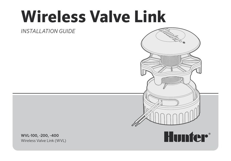
Hunter WVOM User manual

WIRELESS
VALVE OUTPUT
MODULE
INSTALLATION GUIDE
WVOM
Wireless Valve Output Module for Hunter ICC2
and HCC Controllers
MOLDED SYMBOLS
WV-OM Branding/ QR Code
WV-OM
P/MV
LED 1
LED 2
WV-OM-E
PMS 431CPMS 308C
Sticker = white
Print = black
Cyan outline = die line, does not print
QR Code
XXXXXX
P/MV
WV-OM
P/MV
XXXXXX
.526″
.528″

2
You will need:
• WVOM Bluetooth®App (free download from Apple or Google Play)
• Two 9 V DC batteries for each Wireless Valve Link to be connected
• Irrigation-grade, waterproof connectors for DC solenoid connections
• 1½" (38 mm) hole saw for Wireless Valve Link valve box lid mounting
(included)
Note: Do not use the hole saw on the controller enclosure! The hole saw is for
installing the individual Wireless Valve Link devices in valve boxes.
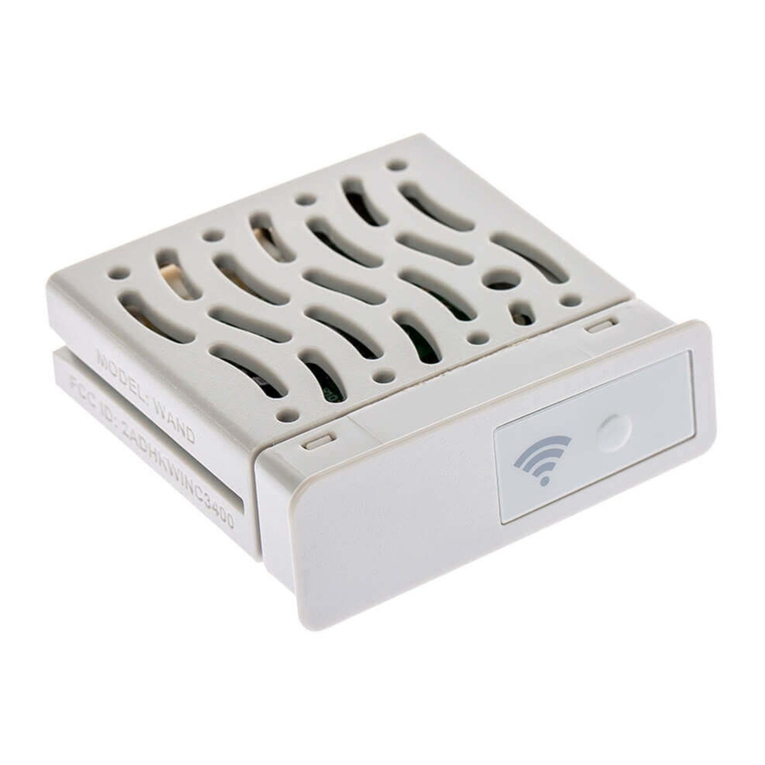
The Wireless Valve Output Module (domestic WVOM or international
WVOM-E model) is designed for installation in an output module slot within
a compatible Hunter ICC2 or HCC Controller.
The Wireless Valve Output Module is designed to operate with Hunter
Wireless Valve Link devices only. It is not compatible with any other
manufacturer’s devices.
The Wireless Valve Link requires Hunter DC-Latching Solenoids
(P/N 458200), which can be retrotted to almost any existing
Hunter valve.
Components
Table of Contents
2Components
3Installation
4Station Programming
5Basic Troubleshooting
6Passcode Creation
6Database Recovery
6Factory Reset
6Firmware Updates
7Compliance
Get the WVL App to get started!
The Bluetooth word mark and logos are registered trademarks owned by
Bluetooth SIG Inc. and any use of such marks by Hunter Industries is under license.
Apple, the Apple logo, and iPhone are trademarks of Apple Inc., registered in the U.S.
and other countries. Google, the Google logo, Android, and Google Play are
trademarks of Google LLC.

3
Installation
RESET
1. Engage the tabs in the output module slot and tip the Wireless Valve
Output Module into place until the connector is fully seated.
2. Move the locking lever to the horizontal position to secure the module.
3. Press and release the Reset button on the back of the facepack so the
new module is recognized. The controller can now manage 54 stations.
4. When powered on, the module's top LED will display a constant green
light to indicate is it active and ready to communicate.
WV-OM
P/MV
P/MV Jumper Wire
➊
➋
➌ ④
PMV Connection: If wireless control of a PMV output will be used,
connect a jumper wire from the PMV terminal on the Wireless Valve
Output Module to the PMV output on the controller power module.
Note

4
The WVOM has no built-in controls; only LEDs to show status. All
programming and diagnostics are done with the free Bluetooth
WVL App, available for iOS®or Android®from their respective app stores.
1. Download and install the Hunter WVL App.
2. Open the app on a smartphone. The app will begin immediately
scanning for Wireless Valve Output Modules within a range of roughly
50' (15 m) line of sight.
3. A list of available Wireless Valve Output Module devices within
Bluetooth range will appear, identied by serial number.
4. Select the Wireless Valve Output Module you're programming and click
Connect. The blue LED on the selected Wireless Valve Output Module
will light up when it's connected to the phone.
5. Consult the Wireless Valve Link installation guide for programming
station addresses into the Wireless Valve Links.
Station Programming
Get the WVL App to get started!
hunter.help/WVL
SCAN
for help
For complete operational and troubleshooting information, visit
the Hunter Support pages.
The Hunter WVL APP is designed for WVL programming and
diagnostics. There is no station manual operation feature within
the app.
Note

5
Basic Troubleshooting
All LoRa®radio communications between the Wireless Valve Output Module
and the Wireless Valve Links (or Repeater) are two-way. Whenever the
Wireless Valve Output Module sends a message to the Wireless Valve Links
or the Repeater, it expects a response.
The two-way communications occur every time the controller attempts to
turn on a Wireless Valve Link station.
If the Wireless Valve Output Module does not receive a response aer a retry
attempt, the module will announce the error both in the controller display
and with two internal beeps every 2 minutes.
• The display will show the station number (or P for Pump/Master
Valve) along with Err to indicate which station failed to respond.
• The beep will continue until either:
• the Wireless Valve Output Module is able to communicate
successfully with the unresponsive Wireless Valve Link
again, or
• you press the Reset button on the back of the controller
facepack.
Use the WVL App to connect to the Wireless Valve Output Module, and go to
the Dashboard menu. Click Details. Any Wireless Valve Link with a red status
icon has failed to respond.
The most common causes of communication failures are:
Cause Solution
Low battery Replace batteries (or inspect solar panel, if using solar
power)
Environmental changes
(e.g., obstructing vehicle,
overgrown foliage)
Locate and remove obstacle, if possible
Elevate Wireless Valve Output Module antenna
Add Repeater
Radio interference from
other devices
Try a dierent channel (use the app) to eliminate
interference
WVL internal failure
(e.g., lightning)
Check Wireless Valve Link LEDs in battery
compartment for functionality
Replace Wireless Valve Link if necessary
The Wireless Valve Output Module range can be extended.
• Elevate the Wireless Valve Output Module antenna with a Hunter
Antenna Extension Kit up to 9' (3 m). The Antenna Extension kit
is required for use in metal cabinet controllers.
• Add a Hunter Repeater (model RPT in North America, RPT-E in
international markets).

6
Additional Functions
Passcode Creation
• You can add a passcode (PIN) to the Wireless Valve Output Module to
prevent unauthorized access by other Bluetooth smartphone users.
• It's important to remember your passcode or store it in a safe place. If
you forget or lose the passcode, other users may no longer be able to
access the Wireless Valve Output Module and all the Wireless Valve Link
information until it's bypassed. Do not use a PIN that you use for other
apps and functions.
Database Recovery
• The recovery feature is used when a Wireless Valve Output Module must
be replaced for service reasons or is exchanged with another device.
• The new Wireless Valve Output Module must be relinked to all the
Wireless Valve Linksin the eld to operate.
• Install the new Wireless Valve Output Module, connect it with the app,
and choose the Recover Database feature.
• The app will prompt you to enter the serial number of a known device
(either a Wireless Valve Link or a Repeater) within the system.
• The Wireless Valve Output Module will use this valid serial number to
search for the new device. The Wireless Valve Output Module will then
attempt to reach all operational Wireless Valve Links or Repeaters within
range. This can take up to 30 minutes.
• When the process is complete, a notication will appear. If all Wireless
Valve Links were found, the Wireless Valve Output Module will be ready
to irrigate again without further eld addressing.
Factory Reset
• The factory reset option will completely erase all Wireless Valve Output
Module information, including the Wireless Valve Link database, Channel
and Site ID assignments, and Repeater conguration. The whole system
will need to be set up again to restore operations.
• From the WVOM Settings menu, select Factory Reset to revert the
system to default settings.
Firmware Updates
• Both the Wireless Valve Output Module and the Wireless Valve Links
can be updated in the eld over the air (OTA), if new rmware becomes
available.
• When the process is complete, a notication will appear. If all Wireless
Valve Links were found, the Wireless Valve Output Module will be ready
to irrigate again without further eld addressing.
Firmware updates are large downloads and can take up to 2 hours.
Do not start an update if you need to irrigate or perform other
diagnostic functions within this time.
Note

7
Compliance
FCC
This equipment has been tested and found to comply with the limits for a
Class B digital device pursuant to Part 15 of the FCC Rules. These limits are
designed to provide reasonable protection against harmful interference in
a residential installation. This equipment generates, uses, and can radiate
radio frequency energy and, if not installed and used in accordance with
the instructions, may cause harmful interference to radio communications.
However, there is no guarantee that interference will not occur in a particular
installation. If this equipment does cause harmful interference to radio or
television reception, which can be determined by turning the equipment o
and on, you are encouraged to try to correct the interference by taking one
or more of the following measures:
• Reorient or relocate the receiving antenna.
• Increase the separation between the equipment and receiver.
• Connect the equipment into an outlet on a circuit dierent from that of
which the receiver is connected.
• Consult the dealer or an experienced radio/TV technician for help.
Changes or modications not expressly approved by Hunter Industries
could void the user’s authority to operate this device. If necessary, consult a
representative of Hunter Industries Inc. or an experienced radio/television
technician for additional suggestions.
This device complies with Part 15 of the FCC Rules. Operation is subject
to the following two conditions: (1) This device may not cause harmful
interference, and (2) this device must accept any interference received,
including interference that may cause undesired operation.
This equipment complies with FCC radiation exposure limits set forth for an
uncontrolled environment. In order to avoid the possibility of exceeding the
FCC radio frequency exposure limits, human proximity to the antenna shall
not be less than 20 cm during normal operation.
This transmitter must not be co-located or operating in conjunction with any
other antenna or transmitter.
ISED
This device contains licence-exempt transmitter(s)/receiver(s) that comply
with Innovation, Science and Economic Development Canada’s licence-
exempt RSS(s). Operation is subject to the following two conditions:
1. This device may not cause interference.
2. This device must accept any interference, including interference that
may cause undesired operation of the device.
Le présent appareil est conforme aux CNR d'Industrie Canada applicables
aux appareils radio exempts de licence. L'exploitation est autorisée aux deux
conditions suivantes:
1. l'appareil ne doit pas produire de brouillage, et
2. l'utilisateur de l'appareil doit accepter tout brouillage radioélectrique
subi, même si le brouillage est susceptible d'en compromettre le
fonctionnement.
This equipment complies with the IC RSS-102 radiation limits set forth for an
uncontrolled environment. This equipment should be installed and operated
with minimum distance of 20 cm from all persons.
Déclaration d’exposition aux radiations:
Cet équipement est conforme aux limites d’exposition aux rayonnements
ISED établies pour un environnement non contrôlé. Cet équipement doit
être installé et utilisé à plus de 20 cm entre le radiateur et votre corps.
This transmitter must not be co-located or operating in conjunction with any
other antenna or transmitter.

HUNTER INDUSTRIES |Built on Innovation®
1940 Diamond Street, San Marcos, CA 92078 USA
hunterindustries.com
© 2023 Hunter Industries Inc. Hunter, the Hunter logo, and other
marks are trademarks of Hunter Industries Inc., registered in the
U.S. and certain other countries. Please recycle.
Helping our customers succeed is what drives us. While our passion for innovation and engineering
is built into everything we do, it is our commitment to exceptional support that we hope will keep you
in the Hunter family of customers for years to come.
Denise Mullikin, President,
Landscape Irrigation and Outdoor Lighting
RC-184 EN 10/23
Table of contents
Other Hunter Control Unit manuals

Hunter
Hunter WVL-100 User manual

Hunter
Hunter Hydrawise WAND User manual

Hunter
Hunter CELL-KIT User manual

Hunter
Hunter HYDRAWISE X2 User manual

Hunter
Hunter Hydrawise WAND User manual

Hunter
Hunter ACC-COM-LTE User manual

Hunter
Hunter PCM-1600 User manual

Hunter
Hunter DUAL 48M Operating instructions

Hunter
Hunter I-40 User manual

Hunter
Hunter A2C-LTE User manual
Popular Control Unit manuals by other brands

Volth
Volth ARGO HYTOS SD1E2X-A2 operating instructions

Metso
Metso M12 Installation maintenance and operating instructions

Philips
Philips LBB 2540/10 installation instructions

AVX
AVX ethertronics ETH-LORA-M-AX-01 Reference manual

Rockwell Automation
Rockwell Automation Allen-Bradley PowerFlex 20-750-PNET user manual

Toa
Toa SP-11N manual