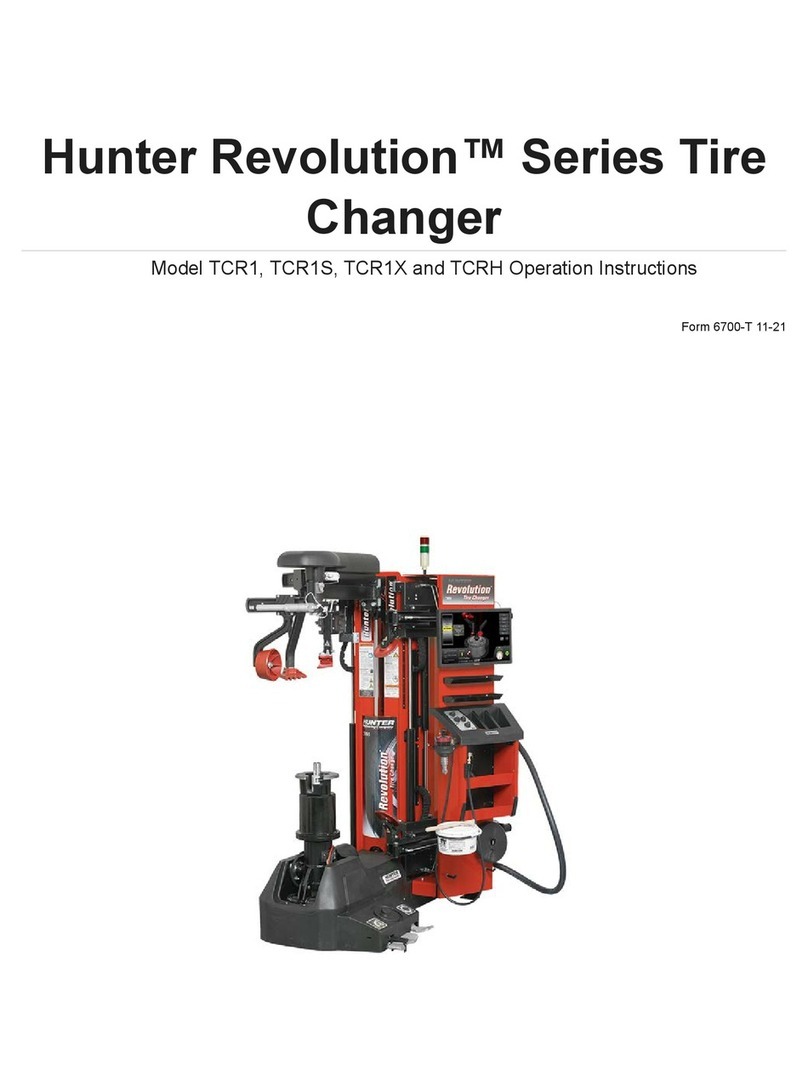
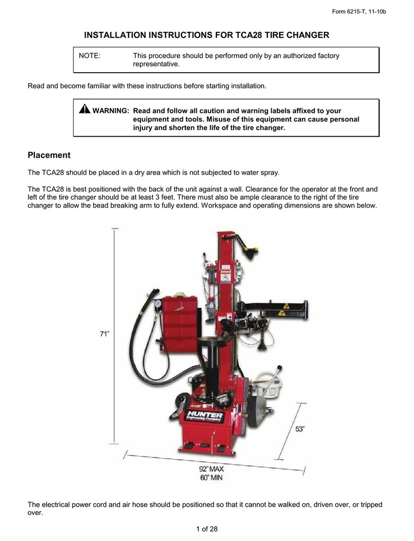
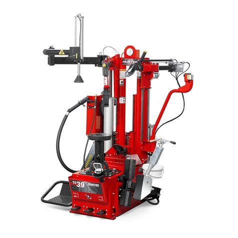
Hunter TCX56 User manual

©Copyright 2009-2012 Hunter Engineering Company
Code 4-132467 01/15
TCX56/57
Tire Changer Family
Operating Instructions
TCX 57
Leverless version
TCX 56
Standard version


Thank you for choosing our Tire Changer
Hunter Engineering Company
Dear Purchaser
Thank you for purchasing your Hunter Tire Changer.
Your Tire Changer has been designed to provide years of safe and dependable service, as long as it is used and
maintained in accordance with the instructions provided in this manual.
All persons who will use and/or maintain this Tire Changer must read, understand and follow all warnings and
instructions provided in this manual, and be properly trained.
This Owner’s Manual should be considered an internal part of your Tire Changer and should remain with the Tire
Changer. However, nothing in this manual, and none of the devices installed on the Tire Changer, substitute for
proper training, careful operation, good judgment and safe work practices.
Always be sure that your Tire Changer is in optimum working order. If you suspect that anything is not working
properly, or that a dangerous situation may exist, immediately shut down the Tire Changer and remedy any condition
before you proceed.
If you have any questions concerning the proper use or maintenance of your Tire Changer, please call your authorized
Hunter Engineering Company representative..
You can also contact Hunter Engineering Company at Tel: 800-448-6848 or 314-731-3020, Fax. 314-731-1776 or use
Sincerely,
Hunter Engineering Company

OWNER INFORMATION
Owner Name _____________________________________________________________________________
Owner Address ___________________________________________________________________________
Model Number____________________________________________________________________________
Serial Number ____________________________________________________________________________
Date Purchased ___________________________________________________________________________
Date Installed ____________________________________________________________________________
Service and Parts Representative ___________________________________________________________
Phone Number____________________________________________________________________________
Sales Representative ______________________________________________________________________
Phone Number____________________________________________________________________________
Training Checklist
Safety Precautions Trained Declined
Warning and Caution Labels
Pinch Points and Other Potential Hazards
Safe Operating Procedures
Maintenance and Performance Checks
Mounting Head Inspection
Adjustment and Filling of Oilers
Bead Breaking
Standard Wheels
Low Prole Wheels
Clamping
Steel Jaw Internal/External Clamping
Demounting
Standard Wheels with Bead Lever and Plastic Sleeve Protector
Full Seating of Mount/Demount Head to Prevent Head Failure
Bead Lubrication During Removal of Low Prole Tires
Reverse Drop Center Wheels

Mounting Trained Declined
Standard Wheels
Mounting of Stiff, Low Prole Tires
Reverse Drop Center Wheels
Proper Bead Lubrication for Mounting Protection
Inflation Trained Declined
Safety Precautions
Lubrication and Removal of Valve Core
Bead Sealing and Seating
Individuals and Dates Trained
___________________________________ ___________________________________
___________________________________ ___________________________________
___________________________________ ___________________________________
___________________________________ ___________________________________
___________________________________ ___________________________________
___________________________________ ___________________________________

Contents
1. Getting Started ....................................................................................... 9
1.1 Introduction...................................................................................................... 9
1.1.a – PURPOSE OF THE MANUAL....................................................... 9
1.2 For Your Safety ............................................................................................. 10
Hazard Denitions ................................................................................. 10
1.3 General Warnings and Instructions ............................................................ 10
Electrical indications .............................................................................. 15
Specic Precautions/Power Source ...................................................... 16
Equipment installation and service ........................................................ 16
Equipment specication ........................................................................ 17
Explanations of symbols ........................................................................ 17
1.3.b. Air Pressures................................................................................ 17
1.4 Special Rim/Tire Considerations ................................................................. 18
1.5 Intended Use of The Machine ...................................................................... 18
1.6 Employee Training ......................................................................................... 18
1.7 Pre-Use Checks............................................................................................. 18
1.8 During Use ..................................................................................................... 19
1.9 Control Pedal Configurations ...................................................................... 19
1.10 Wheel Rotation Pedal ................................................................................. 20
1.11 Tire Bead Breaker Shovel control.............................................................. 20
1.12 Wheel Clamping Pedal................................................................................ 21
1.13 Column Rotation Pedal............................................................................... 21
1.14 Air Inflation Pedal ........................................................................................ 21
1.15 Moving Parts................................................................................................ 22
1.16 Inflator and Pressure Limiter ..................................................................... 22
1.17 Mount / Demount Head .............................................................................. 22
1.18 Equipment Components............................................................................. 24
1.19 Bead Press System (BPS) Components.................................................... 25
2. Basic Procedures ................................................................................ 26
2.1 Bead Breaking ............................................................................................... 26
2.2 Placing Wheel on Tire Changer ................................................................... 27
Clamping the Wheel from Inside of Rim - Steel Rims ........................... 27
Clamping the Wheel from Outside of Rim - Alloy Rims ........................ 28
2.3 Demounting Standard Tire from Rim........................................................... 29
TCX56 - STANDARD MOUNTING HEAD ............................................... 29
Standard Mount / Demount Head ......................................................... 29
Plastic protectors bead lever ................................................................ 29
TCX57 - LEVERLESS MOUNTING HEAD .............................................. 31
Top Bead Demounting ........................................................................... 31
Difcult Tires ......................................................................................... 33
Precautionary Notes .............................................................................. 34
Bottom Bead Demounting with Tool Head ............................................ 35
Bottom Bead Demounting with Disc ..................................................... 36
Difcult Tires .......................................................................................... 37
2.4 Alternate Procedure ..................................................................................... 38
Using the Bead Lever............................................................................. 38

2.5 Mounting Standard Tire to Rim.................................................................... 40
2.6 Mounting of difficult tires: low profile or Run-Flat tires............................. 42
2.7 Match Mounting ............................................................................................ 44
2.8 Tire Inflation .................................................................................................. 45
Special procedure .................................................................................. 46
2.9 Removal of Wheel from Tire Changer ........................................................ 48
2.10 Clamping Jaw Extensions AR46N.............................................................. 49
3. Advanced Procedures ......................................................................... 50
3.1 Advanced Bead Breaking Procedures ........................................................ 50
Bead Breaking “AH” Wheels (e.g. BMW M3, M5, Some Porsches, Range
Rover, Lancia, etc.) ................................................................................ 50
Bead Breaking “AH” Wheels as follows: ............................................... 50
3.2 Advanced Demounting Procedures (for TCX56)......................................... 51
Demounting Tire from Rim Using the Bead Lever Tool without the Plastic
Sleeve Protector .................................................................................... 51
Demounting Upper Bead ...................................................................... 51
Demounting Lower Bead ...................................................................... 51
3.3 Advanced Mounting Procedures ................................................................ 52
3.4 Standard Mount/Demount Head Assembly ............................................... 52
Checking Mount/Demount Head Calibration ........................................ 52
For Steel Heads .................................................................................... 52
Set Position of Steel Mount/Demount Head on Hex Shaft ................... 52
For Plastic Heads .................................................................................. 54
Set Position of Plastic Mount/Demount Head on Hex Shaft ................ 54
Adjust the Offset of Lock Mechanism – Steel and Plastic Heads ......... 55
3.5 Mount/Demount Head Assembly................................................................. 56
Mount/Demount Head Calibration ......................................................... 56
4. Maintenance ........................................................................................ 60
4.1 Maintenance Schedule ................................................................................. 60
4.2 Maintenance and Replacement Parts ......................................................... 62
5. Glossary ................................................................................................ 63
5.1 Rim Diagram .................................................................................................. 63
5.2 Illustrations of Various Rim Designs............................................................ 64


Operation Instructions for TCX56/57 Tire Charger 9
1. Getting Started
1.1 Introduction
1.1.a – PURPOSE OF THE MANUAL
The purpose of this manual is to provide the instructions necessary for optimum operation,
use and maintenance of your machine. If you sell this machine, please deliver this manual
to the new owner. In addition, so we can contact our customers with any necessary safety
information, please ask the new owner to complete and return to Hunter the change of
ownership form attached to the last page of this manual. Alternately, the new owner can
send an email to newuser@hunter.com.
This manual presumes that the technician has a thorough understanding of rim and tire
identication and service. He/she must also have a thorough knowledge of the operation and
safety features of all associated tools (such as the rack, lift, or oor jack) being utilized, and
have the proper hand and power tools necessary to work in a safe manner.
The rst section provides the basic information to safely operate the TCX56/57 tire changer
family. The following sections contain detailed information about equipment, procedures, and
maintenance. “Italics” are used to refer to specic parts of this manual that provide additional
information or explanation. For example, Refer to “Equipment Components” page 24. These
references should be read for additional information to the instructions being presented.
The owner of the tire changer is solely responsible for enforcing safety procedures and
arranging technical training. The tire changer is to be operated only by a qualied and trained
technician. Maintaining records of personnel trained is solely the responsibility of the owner
or management.
The TCX56/57 tire changer family is intended for mounting, demounting, and inating most
tires with an approximate dimension of 40 inches in diameter and 15 inches in width.
Copies of this manual and of the documents accompanying the machine may be obtained
from Hunter Engineering Company by specifying the type of machine and its serial number.
NOTICE: Design details are subject to change. Some illustrations may vary slightly in
appearance from the machine you have.”
An advanced operation section has been provided in “Advanced Procedures,” page 50.

Operation Instructions for TCX56/57 Tire Charger
10
1.2 For Your Safety
Hazard Definitions
These symbols identify situations that could be detrimental to your safety and/or cause
equipment damage.
DANGER: Indicates an imminently hazardous situation which, if not avoided,
will result in death or serious injury.
DANGER
WARNING: Indicates a potentially hazardous situation which, if not avoided,
could result in death or serious injury.
WARNING
CAUTION: Indicates a potentially hazardous situation which, if not avoided,
may result in minor or moderate injury.
CAUTION
NOTICE: Used without the safety alert symbol indicates potentially hazardous
situation, which, if not avoided, may result in property damage.
NOTICE
1.3 General Warnings and Instructions
Avoid Personal Injury. Carefully read, understand and follow the warnings and
instructions given in this manual. This manual is an essential part of the product.
Keep it with the machine in a safe place for future reference.
WARNING
1. If the use and maintenance procedures provided in this manual are not properly
performed, or the other instructions in this manual are not followed, an accident could
occur. Throughout this manual reference is made that “an accident” could occur. Any
accident could cause you or a bystander to sustain severe personal injury or death, or
result in property damage.

Operation Instructions for TCX56/57 Tire Charger 11
2. Overinated tires can explode, producing hazardous ying debris that may result in an
accident.
3. Tires and Rims that are not the same diameter are “mismatched.” never attempt to mount
or inate any tire and rim that are mismatched. For example, never mount a 16.5” tire
on a 16” rim and vice versa. This is very dangerous. A mismatched tire and rim could
explode, and resulting in an accident.
4. Never exceed the bead setting pressure (gauge on hose) provided by the tire
manufacturer, as stated on the sidewall of the tire.
5. Never place your head or any part of your body over a tire during ination process or
when attempting to seat beads. This machine is not intended to be a restraining device
for exploding tires, tubes or rims.
6. Always stand back from tire changer when inating, never lean over.
An exploding tire and rim may be propelled upward and outward with enough force
to cause serious injury or death.
Never mount any tire unless the tire size (molded into the sidewall) matches the rim
size (stamped into the rim) exactly or if the rim or tire are defective.
Never exceed tire pressure recommended by tire manufacturer.
This tire changer is not a safety device and will not restrain exploding tires and rims.
keep area clear of bystanders.
DANGER
7. Crushing Hazard. Moving Parts Present. Contact with moving parts could result in an
accident.
• Only one operator may work with the machine at a
time.
• Keep all bystanders clear of tire changer.
• Keep hands and ngers clear of rim edge during
demounting and mounting process.
• Keep hands and ngers clear of mount/demount
head during operation.
• Keep hands and other body parts away from
moving parts.
• Do not use tools other than those supplied with tire
changer.
• Use proper tire lubricate to prevent tire binding.
Avoid Personal Injury. Carefully read, understand and follow the warnings and
instructions given in this manual. This manual is an essential part of the product.
Keep it with the machine in a safe place for future reference.
WARNING

Operation Instructions for TCX56/57 Tire Charger
12
8. Electric Shock Hazard.
• Never hose down or power wash electric tire
changers.
• Do not operate machine with a damaged power cord
• If an extension cord is necessary, a cord with a
current rating equal to or greater than that of the
machine must be used. Cords rated for less current
than the machine can overheat, resulting in a re.
• Care should be taken to arrange the cord so that it
will not be tripped over or pulled.
9. Risk of Eye Injury. Flying debris, dirt and uids may be discharged during bead seating
and ination process. Remove any debris from the tire tread, wheel surfaces. Wear
OSHA approved safety glasses during mount and demount procedures.
10.Always inspect the machine carefully before using it. Missing, broken, or worn equipment
(including warning stickers) must be repaired or replaced prior to operation.
11.Never leave nuts, bolts, tools or other equipment on the machine. They may become
trapped between moving parts and cause a malfunction.
12.NEVER install or inate tires that are cut, damaged, rotten or worn. NEVER install a tire on
a cracked, bent, rusted, worm, deformed or damaged rim.
13.If a tire becomes damaged during the mounting process, do not attempt to nish
mounting. Remove from service area and properly mark the tire as damaged.
14.To inate tires, use short bursts while carefully monitoring the pressure, tire, rim and
bead. NEVER exceed tire manufacturer’s pressure limits.
15.This equipment has internal arcing or sparking parts which should not be exposed to
ammable vapors (gasoline, paint thinners, solvents, etc.). This machine should not be
located in a recessed area or below oor level.
16.Never operate the machine if you are under the effects of alcohol, medications and/or
drugs. If you are taking prescription or over the counter medication, you must consult a
medical professional regarding any side effects of the medication that could hinder your
ability to operate the machine safely.
17.Always use OHSA approved and mandated Personal Protective Equipment (PPE) during
use of the machine. See your supervisor for more instructions.
18.Remove jewelry, watches, loose clothing, ties and restrain long hair before using machine.
19.Wear non-slip safety footwear when operating the tire changer.
20.Wear proper back support and employ proper lifting technique when placing, moving,
lifting or removing wheels from the tire changer.
21.This machine may only be used, maintained or repaired by properly trained employees of
your company. Repairs should only be performed by qualied personnel. Your Hunter
service representative is the most qualied person. The employer is responsible for
determining if an employee is qualied to safely make any repairs to the machine should
repair be attempted by users.
22.The user should understand all warnings decals afxed to this equipment before
operating.
23. Do not lock the rim on the turntable during ination
Avoid Personal Injury. Carefully read, understand and follow the warnings and
instructions given in this manual. This manual is an essential part of the product.
Keep it with the machine in a safe place for future reference.
WARNING

Operation Instructions for TCX56/57 Tire Charger 13

Operation Instructions for TCX56/57 Tire Charger
14
DECAL PLACEMENT TCX 56
Standard Version
TCX 57
Leverless Version
3
2
5
91
14
1610
8
9
13
7
9
6
4
18
11 15 17
14
11
16
12
19
IIAXXXXXX
ANNODI COSTRUZIONE/
MANUFACTURED20XX
0-11XXXXXX/XX
MADE IN ITALY
Port.max
11250 HUNTER DRIVE
BRIDGETON,
MISSOURI 63044
HUNTER ENGINEERING COMPANY
XX/XX
XX/XX ac
X
XX
XX
/XX-XX
A
V
lb
kW
Hz
Ph
TCX500E SERIESModel
Serial N.
XX
bar/psi
Code

Operation Instructions for TCX56/57 Tire Charger 15
No. Part Number Description
1 RP11-4-402023 DECAL-RIM, TABLE, BEAD BREAKER, BEAD AIR PRESSURE
2 RP11-4-132526 DECAL-HUNTER LOGO
3 RP11-4-113623 DECAL-PEDAL OPERATION
4 RP11-4-402030 DECAL-INFLATION PEDAL OPERATION
5 RP11-3020842 DECAL-TABLE ROTATION
6 Rif. SN DECAL-MODEL SERIAL NUMBER
7 RP11-4-402027 DECAL-MAXIMUM INLET PRESSURE
8 RP11-4-402018 DECAL-HUNTER BEAD PRESS SYSTEM
9 RP11-3013640 DECAL-ARROWS UP-DOWN
10 RP11-4-402021 DECAL-MANUAL TIRE BLEED VALVE
11 RP11-4-402038 DECAL-VERTICAL COMUMN LOCK BUTTON OPERATION
12 RP11-4-115412 DECAL-DANGER-WARNING INDICATION
13 RP11-3016568 DECAL-BPS LOCK
14 RP11-4-115411 DECAL-DANGER OPERATION
15 RP11-4-407099 DECAL-TOOL MOVEMENT
16 RP11-4-115243 DECAL-WARNING OPERATION
17 RP11-4-113552 DECAL-TL TOOL LABEL
18 RP11-4-115246 DECAL-ELECTRICAL HAZARD
19 RP11-4-113016 DECAL-RECOMMENDED TPMS SENSOR START POSITION
20 Rif. SN DECAL-BPS SERIAL NUMBER (NOT SHOWN)
Electrical indications
The TCX56/57 is manufactured to operate at a specic voltage and amperage rating.
Make sure that the appropriate electrical supply circuit is of the same voltage and amperage
ratings as marked on the TCX56/57.
FIRE HAZARD. DO NOT ALTER THE ELECTRICAL PLUG.
WARNING
Plugging the electrical plug into an unsuitable supply circuit will damage the
equipment.
NOTICE

Operation Instructions for TCX56/57 Tire Charger
16
• HAZARDOUS VOLTAGE
• Turn of and lock out system power before
servicing.
• Contact may cause electric shock or death
DANGER
Make sure that the electrical supply circuit and the appropriate receptacle is installed with
proper grounding.
To prevent the possibility of electrical shock injury or damage to the equipment when
servicing the TCX56/57, power must be disconnected by removing the power cord from the
electrical power outlet.
After servicing, be sure the TCX56/57 ON/OFF switch is in the “O” (off) position before
plugging the power cord into the electrical power outlet.
Specific Precautions/Power Source
The TCX56/57 is equipped with motoinverter, (220VAC / 1PH / 50-60Hz) and standard plug
220V L6-20P plug.
This machine must be connected to a 20 amp branch circuit. Please refer all power source
issues to a certied electrician.
WARNING
A protective ground connection, through the grounding conductor in the power cord,
is essential for safe operation. Use only a power cord that is in good condition.
Equipment installation and service
A factory-authorized representative should perform installation.
This equipment contains no user serviceable parts. All repairs must be referred to a qualied
Hunter Service Representative

Operation Instructions for TCX56/57 Tire Charger 17
Equipment specification
Electrical
Voltage: 220 VAC, 1 phase, 50-60 Hz, includes NEMA L6-20P
Amperage: 20 amperes
Air
Air Pressure Requirements: 115-175 PSI (7.9-12.0 bar)
Approximate Air
Consumption:
at 8 bar = 6 Lt/s •0.2118 Ft3/s •12,70 CFM (ft3/min)
at 10 bar = 7,76 Lt/s •0.2471 Ft3/s •14,82 CFM (ft3/min)
Mechanical
Clamping System Rotating
Speed:
CW – 7 rpm and 17 rpm
CCW – 7rpm
Max. Tire Diameter: 43.3 in. w/BPS
Max Bead Roller Opening
Width: 15 in.
Diameter Range: 10-30
Explanations of symbols
These symbols may appear on the equipment.
Alternating current.
Earth ground terminal.
Protective conductor terminal.
Risk of electrical shock.
1.3.b. Air Pressures
The machine is equipped with an internal pressure limiting valve to minimize the risk of over
inating the tire.
•EXPLOSION HAZARD
•Never exceed tire pressure recommended by
tire manufacturer. Never mismatch tire size
and rim size.
•Avoid personal injury or death
DANGER
1. Never exceed these pressure limitations:
• Supply line pressure (from compressor) is 220 psi.
• Operating pressure (gauge on regulator) is 145 psi.
Bead setting pressure (gauge on hose) is the tire manufacturer’s maximum pressure as
stated on the sidewall of the tire
2. Activate air ination jets only when sealing bead.

Operation Instructions for TCX56/57 Tire Charger
18
3. Bleed air pressure system before disconnecting supply line or other pneumatic
components. Air is stored in a reservoir for operation of ination jets.
4. Only activate the air ination jets if the rim securing device is locked in place and the tire
is properly clamped (when possible).
1.4 Special Rim/Tire Considerations
Wheels equipped with low tire pressure sensors or special tire and rim designs may
require certain procedures. Consult wheels and tire manufacturer’s service manuals.
NOTICE
1.5 Intended Use of The Machine
This machine must be used only to remove and replace an automotive tire on an automotive
rim or a motorcycle tire on a motorcycle rim, using the tools with which it is equipped. Any
other use is improper and can result in an accident.
1.6 Employee Training
1. The employer is obligated to provide a program to train all employees who service rim
wheels in the hazards involved in servicing those rim wheels and the safety procedures to
be followed. Service or servicing means the mounting and demounting of rim wheels, and
related activities such as inating, deating, installing, removing and handling.
• The employer shall insure that no employee services any rim wheel unless the employee
has been trained and instructed in correct procedures of servicing the type of wheel
being serviced, and in the safe operating procedures.
• Information to be used in the training program shall include, at a minimum, the
applicable information contained in this manual.
2. The employer shall ensure that each employee demonstrates and maintains the ability to
service rim wheels safely, including performance of the following tasks:
• Demounting of tires (including deation).
• Inspection and identication of the rim wheel components.
• Mounting of tires.
• Use of any restraining device, cage, barrier, or other installation.
• Handling of rim wheels.
• Ination of the tire.
• Understanding the necessity of stand back from tire changer during ination of the tire
and during inspection of the rim wheel following ination, never loan over.
• Installation and removal of rim wheels.
3. The employer shall evaluate each employee’s ability to perform these tasks and to service
rim wheels safely, and shall provide additional training as necessary to assure that each
employee maintains his or her prociency.
1.7 Pre-Use Checks
Before beginning work, carefully check that all components of the machine, especially rubber
or plastic parts, are in place, in good condition and working properly. If the inspection reveals
any damage or excessive wear, no matter how slight, immediately replace or repair the
component.

Operation Instructions for TCX56/57 Tire Charger 19
Walk around the machine to ensure that all components are in good condition and
operational, and that there are no foreign objects or debris (rags, tools, etc…) in or about the
machine which could affect its operation.
These checks must be carried out:
• Before starting the machine.
• At regular time intervals.
• After any modication or repair.
The machine may only be started after this pre-use check is successfully completed.
Do not use the machine if it is placed out of service for tune up, maintenance, lubrication,
etc.
1.8 During Use
In the event you hear any strange noise or feel unusual vibration, if a component or system
is not operating properly, or if there is anything unusual at all, stop using the machine
immediately.
• Identify the cause and take any necessary remedial action.
• Contact your supervisor if necessary.
Never allow any bystander to be within 20 feet of the machine during operation.
To stop the machine in an emergency:
• disconnect the power supply plug;
• cut off the compressed air supply network by disconnecting the shut-off valve (snap
coupling).
1.9 Control Pedal Configurations
Avoid unintended machine moviment and personal injury.
Pay close attention to the configuration of your machine.
WARNING
Control pedals on the TCX56/57 tire changer are congured as shown below:
NOTICE
If the unit is equipped with a wheel lift, there is an additional pedal at the far right
upper portion of the face of the unit.

Operation Instructions for TCX56/57 Tire Charger
20
Throughout this manual, control pedals are referred to by the associated symbol.
The PowerOut system provides bead breaking controls on the handle for convenience,
particularly with larger diameter assemblies.
1.10 Wheel Rotation Pedal
Step down on the rotation pedal to rotate the wheel clockwise.
Release the pedal to stop rotation. Depressing the pedal halfway rotates
the wheel at slow speed. Depressing the pedal all the way rotates the
wheel at fast speed.
Lift up on the pedal to rotate the wheel counterclockwise. Release the
pedal to stop rotation.
1.11 Tire Bead Breaker Shovel control
Keep arms and legs from between the bead breaker arm and the side of the housing.
WARNING
4-402023
CRUSH HAZARD CRUSH HAZARD EXPLOSION HAZARD
Press the “In” button to close bead breaker arm and loosen bead (red arrow).
Press the “Out” button to allow the bead breaker arm to open (black arrow).
This manual suits for next models
1
Table of contents
Other Hunter Tyre Changer manuals

Hunter
Hunter TCX575 User manual

Hunter
Hunter TCX50 User manual

Hunter
Hunter TCA34R Series User manual

Hunter
Hunter TC33 Series User manual

Hunter
Hunter Maverick Series User manual

Hunter
Hunter TC39 Series User manual

Hunter
Hunter TCX50H Series User manual

Hunter
Hunter TCX3000 User manual

Hunter
Hunter TCX450 User manual

Hunter
Hunter Revolution Series User manual