4
Operations & Parts Manual
Model No. CAT851
General Safety Information
Read Operating Instructions
Always become familiar with all the instructions and
warnings before operating any pneumatic tool.
Always Wear Approved Eye protection
Impact resistant eye protection should meet or exceed the
standards as set forth in the United States ANSI Z87.1,
Occupational and Educational Eye and Face Protection.
Look for the marking Z87.1 on your eye protection to
insure that it is an approved style. For further information,
ANSI Z87.1. Occupational and Educational Eye and Face
Protection, is available from the American National
Standards Institute, Inc., 11 West 42nd Street, New York,
NY10036.
Hearing Protection is Recommended
Hearing protection should be used when the noise level
exposure equals or exceeds an 8 hour time-weighted
average sound level of 85dBA. Process noises, reflective
surfaces, other tools being operated nearby, all add to the
noise level present in your work area. If you are unable to
determine your noise level exposure, we recommend the
use of hearing protection.
Use a face mask/respirator when spraying
Always spray in a well ventilated area to prevent health
and fire hazards.
Avoid Prolonged Exposure to Vibration
Pneumatic tools can vibrate during use. Prolonged ex-
posure to vibration or very repetitive hand and arm move-
ments, can cause injury. Stop using any tool if discomfort,
tingling, feeling of pain occurs. You should consult your
physician before resuming use of the tool.
90 PSIG Maximum
Husky tools are designed to operate at an air pressure of
90 pounds per square inch gauge pressure (90 PSIG)
maximum, at the tool. Use of higher air pressure can, and
may cause injury. Also use of higher air pressure places
the internal components under loads and stresses they
were not designed for causing premature tool failure. The
air supply should be clean and dry, preferably lubricated.
For best results drain the moisture from your compressor
daily.
WARNING:
SOME DUST CREATED BY POWER SANDING, SAWING,
GRINDING, DRILLING, AND OTHER CONSTUCTION
ACTIVITIES CONTAINS CHEMICALS KNOWN TO
CAUSE CANCER, BIRTH DEFECTS OR REPRODUC-
TIVE HARM. SOME EXAMPLES OF THESE CHEMI-
CALS ARE:
LEAD FROM LEAD-BASED PAINTS
CRYSTALLINE SILICA FROM BRICKS, CEMENT AND
OTHER MASONRY PRODUCTS
ARSENIC AND CHROMIUM FROM CHEMICALLY THR-
EAD LUMBER
YOUR RISK FROM THESE EXPOSURES VARIES,
DEPENDING ON HOW OFTEN YOU DO THIS TYPE OF
WORK. TO REDUCE YOUR EXPOSURE TO THESE
CHEMICALS, WORK IN A WELL VENTILATED AREA
AND WORK WITH APPROVED SAFETY EQUIPMENT
SUCH AS THOSE DUST MASKS THAT ARE SPECIALLY
DESIGNED TO FILTER OUT MICROSCOPIC PARTI-
CLES.
Specific Tool Safety Information
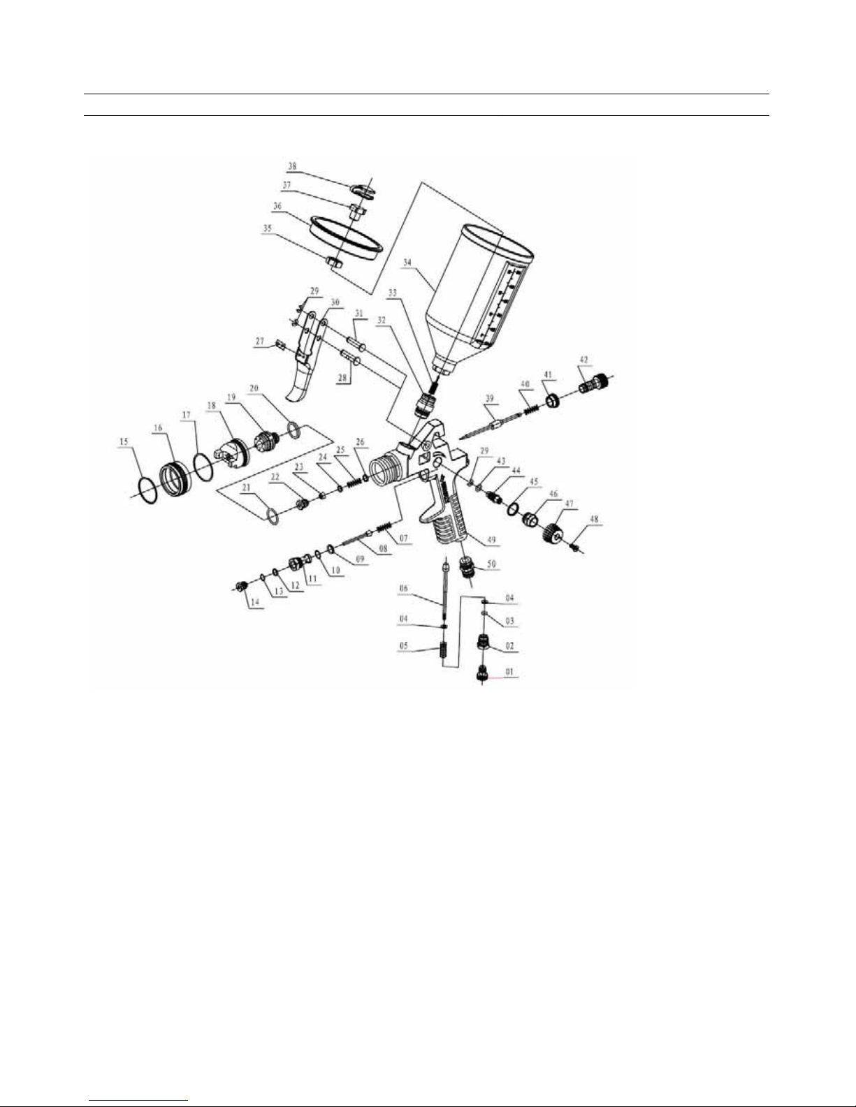
HVLP Gravity Feed Spray Gun
Do not spray flammable materials
Never aim air spray gun at people. Solvents and
thinners would cause serious injury.
Impact Wrench Accessories
Use Only Impact Sockets and Accessories
Use only sockets designed "For use with Impact Wrenches".
Hand tool sockets can break creating a hazard from flying
pieces. Always check sockets, retainers and drivers and drives
regularly for wear of damage and replace whenever necessary.
Ratchet Wrench Accessories
Use Only Power Sockets and Accessories
Sockets and accessories used shall be of the power socket
type. Always check sockets, retainers and drives regularly for
wear or damage and replace whenever necessary.
Die Grinder Accessories
Use Only Recommended Grinding Stones
Use Tool only after inspection of stones, collet and hoses.
Repair or replace worn items before use. Only use accessories
of the correct size for the tool. The grinding stones’ shank
should be to within 1/4"size of the collet nut to prevent
vibration while operating the tool.
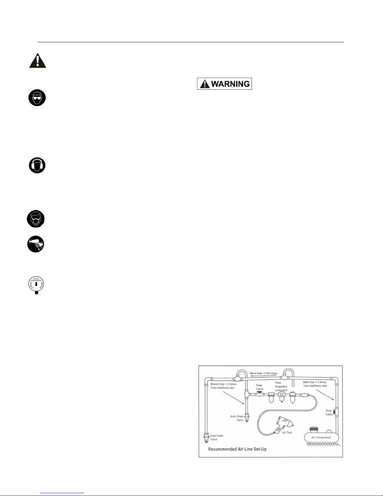
Installation
Always use clean dry air. Excessive moisture and dirt will
greatly reduce the life of any air motor. We recommend the
installation of an in-line filter-regulator-lubricator as close to the
tool as possible.
A 3/8"air hose is required up to a length of 8 ft. If more length is
required a 1/2"air hose should be connected to the 3/8"hose to
ensure the tool had the necessary air supply. Be sure all hoses
and fittings are the correct size and tightly secured.
Before the tool is connected to the air supply, clear the air hose
of accumulated dust and moisture. Before removing a tool for
service or changing accessories, make sure the air line is
shut-off and drained of air. This will prevent the tool from
operating if the tool is accidentally engaged.