Husqvarna 967187001 Instruction manual

Workshop manual
Rider Battery
English


English – 3
Workshop Manual
Husqvarna Rider Battery
Table of contents
Table of contents
Husqvarna AB has a policy of continuous product development and therefore reserves the right to modify
the design and appearance of products without prior notice.
1 Index ...................................................................4
2 Introduction and Safety Regulations...................7
3 Special Tools ....................................................11
4 Technical Data ..................................................14
5 Design and Function.........................................15
6 Basic Dismantle/Assembly ...............................19
7 Repair Work ......................................................33
8 Repair Work Electrical Components .................64
9 Troubleshooting with Common Service Tool ....77
10 Description of Electrical System .....................81
11 CST Autotest ...................................................97
12 CST-Drive Mode Logging .............................115
13 Manual CST Tests ........................................125
14 Batteries and Maintenance ...........................137

English – 4
Index
1 Index
1 Index .............................................................................. 4
2 Introduction and Safety Regulations .......................... 7
2.1 General ................................................................. 7
2.2 Safety ................................................................... 7
2.3 Target Group ......................................................... 7
2.4 Changes ............................................................... 7
2.5 Tools ..................................................................... 7
2.6 Parts and Accessories .......................................... 7
2.7 Structure ............................................................... 7
2.8 Numbering ............................................................ 7
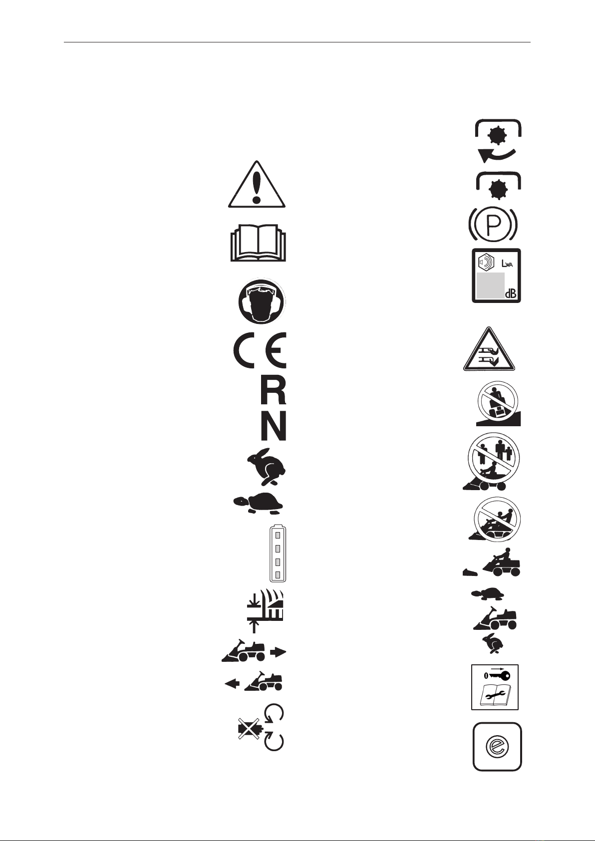
2.9 Symbols on Rider ................................................. 8
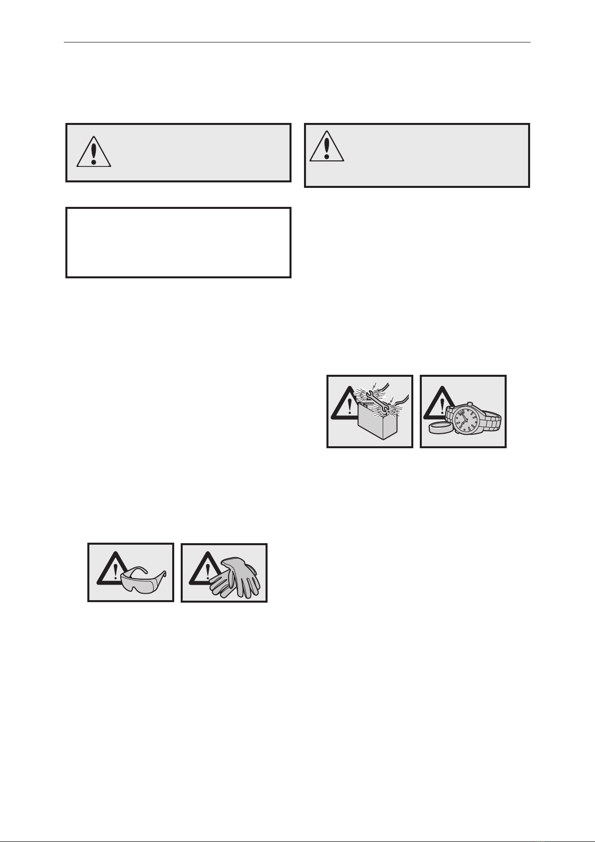
2.10 Special Safety Instructions ................................. 9
2.11 Risk of Sparks ..................................................... 9
2.12 Cutting Power ................................................... 10
3 Special Tools ............................................................... 11
4 Technical Data ............................................................ 14
5 Design and Function .................................................. 15
5.1 Administration ..................................................... 15
5.2 Wheels ................................................................ 15
5.3 Serial Number ..................................................... 16
5.4 Steering .............................................................. 17
5.5 Cutting Deck ....................................................... 18
5.6 Service Position for Cutting Deck ....................... 18
5.7 Removing the BioClip Plug ................................. 18
6 Basic Dismantle/Assembly ........................................ 19
6.1 Wheels ................................................................ 20
6.2 Covers ................................................................ 21
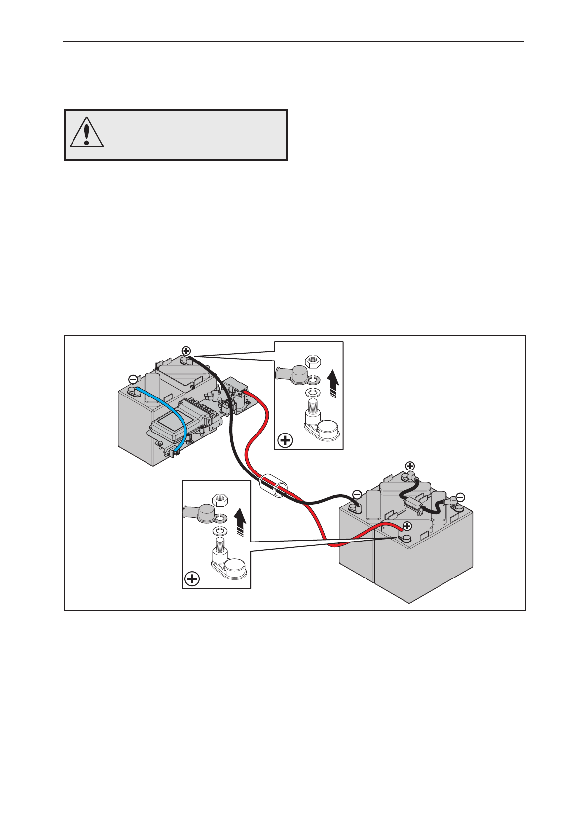
6.3 Front Batteries .................................................... 25
6.4 Rear Battery ....................................................... 27
6.5 Exploded View Drawing Cutting Deck ................ 28
6.6 Removing the Cutting Deck ................................ 29
6.7 Assembling the Cutting Unit ............................... 31
7 Repair Work ................................................................ 33
7.1 Replacing the Steering Cables ........................... 34
7.2 Removing/Fitting the Steering Shaft ................... 35
7.3 Removing/Assembling the Cable Pulley ............. 36
7.4 Replacing Brake Cable ....................................... 37
7.5 Checking and Adjusting the Brake Cable ........... 37
7.6 Changing Articulated Steering Bearing ............... 37
7.7 Removing the Pendulum Shaft ........................... 40
7.8 Replacing the Pendulum Shaft Bushings ........... 41
7.9 Assembling the Pendulum Shaft ......................... 41
7.10 Removal of Blades and Blade Adapter ............. 43
7.11 Grinding and Balancing Blades ........................ 44
7.12 Removing the Blade Motor ............................... 45
7.13 Loosen the Pedal Plate .................................... 48
7.14 Changing Microswitch, P-brake ........................ 52
7.15 Changing Microswitch, Reverse Drive .............. 53
7.16 Changing Microswitch, Forward Drive .............. 54
7.17 Changing Speed Potentiometer ....................... 56
7.18 Changing Recoil Spring in Pedal Plate ............. 57
7.19 Calibrating Speed Potentiometer ...................... 59
7.20 Calibrating Speed ............................................. 60
7.21 Assemble New Bafe Plate .............................. 61
7.22 Changing Microswitch, Bafe Plate .................. 63
8 Repair Work Electrical Components ........................ 64
8.1 Changing Seat Switch ........................................ 65
8.2 Changing Control Panel ..................................... 67
8.3 Changing Key Switch ........................................ 68
8.4 Changing Drive Motor ......................................... 69
8.5 Changing Control Unit (CCU) ............................. 74
8.6 Changing Fuses ................................................. 76
9 Troubleshooting with Common Service Tool .......... 77
9.1 Common Service Tool (CST) .............................. 78
9.2 Connecting CST ................................................. 78
9.3 Component Locations, Electrical System ........... 79
9.4 Electrical Components ........................................ 80
10 Description of Electrical System............................. 81
10.1 Cable Drawing .................................................. 82
10.2 Wiring Diagram (cutting motor control ver. 1) ... 84
10.3 Wiring Diagram (cutting motor control ver. 2) ... 86
10.4 Description of CCU ........................................... 88
10.5 Contacts ........................................................... 92
10.6 Description of Cables ....................................... 93
11 CST Autotest ............................................................. 97
11.1 Power Supply .................................... 98
11.1.1 Test of +36 V ..........................................98
11.1.2 Test of +5 V ............................................99
11.2 Switches ..........................................107
11.2.1 Test of Cutting Deck ...............................107
11.2.2 Test of Seat Switch ................................108
11.3 Pedals ..............................................109
11.3.1 Test of Switch for Forward Pedal ...........109
11.3.2 Test of Switch for Reverse Pedal ...........110
11.3.3 Test of Switch for P-Brake .....................110
11.4 Keypad ............................................. 111
11.4.1 Test of LED ............................................111
11.4.2 Test of Buttons .......................................111
11.5 Miscellaneous ................................. 113
11.5.1 Test of Charger ......................................113

English – 5
Index
12 CST-Drive Mode Logging ....................................... 115
12.1 Manual Drive Mode Logging ............................116
12.2 Keypad Buttons ...............................................116
12.3 Main Relay .......................................................116
12.4 Troubleshooting the Main Relay ......................116
12.5 Electrical Circuit Diagram ...............................117
12.6 Troubleshooting with Circuit Diagram ..............118
12.7 Switches ..........................................................119
12.8 Pedals ............................................................. 121
12.9 Keypads LEDs ................................................ 121
12.10 Miscellaneous ............................................... 122
12.11 Total Battery Current .................................... 122
12.12 Drive Motor Error .......................................... 123
12.13 Cutting Motor Signals ................................... 123
12.14 Cutting Deck Status ...................................... 123
12.15 Activating the Cutting Unit ............................ 124
12.16 Cutting Motor Signals ................................... 124
13 Manual CST Tests ................................................... 125
13.1 Manual CST Tests .......................................... 126
13.2 Lift Switch ...................................................... 126
13.3 Seat Switch ..................................................... 127
13.4 Cutting Deck Status ........................................ 127
13.5 Pedals ............................................................. 128
13.6 Speed Potentiometer ...................................... 128
13.7 Forward Pedal Switch ..................................... 129
13.8 Forward Pedal Switch ..................................... 129
13.9 P-brake Pedal Switch ..................................... 130
13.10 Main LED’s ................................................... 131
13.11 Test Activation LED on .................................. 131
13.12 Test SavE LED on ........................................ 131
13.13 Test Error LED on ......................................... 132
13.14 Battery LEDs ................................................ 132
13.15 Battery 100 % LED on .................................. 132
13.16 Battery 75 % LED on .................................... 133
13.17 Battery 50 % LED on .................................... 133
13.18 Battery 25 % LED on .................................... 134
13.19 Battery Low LED on ...................................... 134
13.20 Keypad Buttons ............................................ 135
13.21 Activation ...................................................... 135
13.22 SavE ............................................................. 135
13.23 Miscellaneous ............................................... 136
13.24 Charger Status ............................................. 136
14 Batteries and Maintenance .................................... 137
14.1 Battery Maintenance ....................................... 138
14.2 Measures when Rider Taken Out of Service .. 138
14.3 Before Taking into Service .............................. 138
14.4 Battery Information ......................................... 139
14.5 Why Must the Battery be Charged? ............... 139
14.6 When is a 12V Battery Fully Charged? ......... 140
14.7 Hydrometer ..................................................... 140
14.8 How to Take Care of Batteries ........................ 141
14.9 Why Does a Battery Get Warm
When Charging? ..................................................... 141
14.10 Explosion Risk! ............................................. 141
14.11 What is the Normal Charge
Current and Charge Voltage of a Battery? ............. 141
14.12 When Does a Battery Freeze? ..................... 141
14.13 What Does a Battery Contain and
Where Can it Be Disposed Of? .............................. 141
14.14 Husqvarna's Battery Charger ....................... 141
14.16 Lead Sulfate, What is It? .............................. 142
14.17 Charge Voltages for
Three Series Connected Lead-Acid Batteries ........ 142

English – 6
Date Page Revision Signature
Revision ledger
Enter any revisions and corrections to the
workshop manual into the table below. Revision
can be notied by Husqvarna AB as service
information or the equivalent.
Enter the service notes into the troubleshooting
software Common Service Tool (CST)

English – 7
2 Introduction and Safety Regulations
2.1 General
This Workshop Manual provides a comprehensive
description of how to trouble shoot, repair and test
the Rider.
A description of different safety steps that must be
taken during repair work is also given.
2.2 Safety
Note! The section dealing with safety must be read
and understood by all those carrying out repair
work or service on the Rider.
Warning symbols can be found in this Workshop
Manual and on the Rider. See"2.9 Symbols on
Rider" A new warning symbol decal must be
applied as soon as possible if a warning symbol
on the Rider has been damaged or is missing so
that the greatest level of safety can be maintained
when using the Rider.
2.3 Target Group
This Workshop Manual is written for personnel
assumed to have a good knowledge about the
repair and service of ride-on mowers.
The Workshop Manual must be read and
understood by personnel who will carry out repair
work and service on the Rider. The Manual is also
suitable for use when training new employees.
2.4 Changes
Any modications to the Rider will be gradually
introduced into ongoing production. As these
modications affect service and/or spare parts,
specic service information will be sent out
when necessary. This can mean that in time this
Workshop Manual will become out of date.
In order to prevent this, the Manual should be read
together with all service information concerning the
Rider in question.
2.5 Tools
Special tools are required for some stages.
All service tools are listed in the Workshop
Manual.
Usage is made evident in each section.
2.6 Parts and Accessories
Always use original Husqvarna
• Spare parts
• Service tools
• Accessories
or you may invalidate the warranty and risk your
personal safety.
2.7 Structure
This Workshop Manual can be used in two
different ways:
• Troubleshooting and repair of a certain system
on the Rider.
• Dismantling, assembling and upgrading of the
Rider.
1. Look up the page for the system in question.
2. Carry out the following steps:
• Dismantling
• Repairing
• Assembling
Proceed as follows to dismantle and assemble the
Rider:
1. Open the chapter "Basic dismantle" and carry
out dismantling in the order set out in the sections.
2. Open Chapter "7 Repairs" and carry out repairs
in the order set out in the sections.
3. Carry out diagnostic trouble shooting with
the Common Service Tool (CST) if a fault
in the electrical system is suspected, see
"9 Troubleshooting with Common Service Tool".
This software can be downloaded from the
Husqvarna website.
4. Order or collect all requisite spare parts from the
stores.
Refer to the exploded view drawing (IPL) for the
sub-system in question.
5. Carry out Assembly in the order set out in the
sections.
2.8 Numbering
Position references to components in the gures
are designated A, B, etc.
The gures are numbered 1, 2 etc.
The position references and gure numbers restart
in each new section.
Introduction and safety regulations

English – 8
Introduction and safety regulations
2.9 Symbols on Rider
These symbols can be found on the ride-on mower
and in the manual.
WARNING! Careless or incorrect
use can result in serious or fatal
injury to the operator or others.
Please read the Operator’s
Manual carefully and make sure
you understand the instructions
before using the machine.
Use ear protection.
This product complies with
applicable EC directives.
Reverse.
Neutral.
Fast.
Slow.
Indicates battery status.
Cutting height.
Backward.
Forward.
Warning for rotating parts.
Mind your hands and feet.
Clutch in.
Clutch out.
Parking brake.
Noise emissions to surroundings
in accordance with the European
Union's directive. The machine's
emissions are set out in the
chapter Technical data and on the
decal.
Rotating blades Keep hands and
feet away from under the hood
when the engine is running
Never drive directly across a
slope.
Never use the ride-on mower if
persons, especially children or
pets, are in the immediate vicinity.
Never carry passengers on
the ride-on mower or on its
accessories.
Drive very slowly without the
cutting deck
The cutting deck must be tted at
full speed.
Remove the ignition key before
carrying out repair work or
maintenance.
Remove the ignition key before
carrying out repair work or
maintenance.
Battery‐saving function.

English – 9
Introduction and safety regulations
This Workshop Manual contains the following
warning boxes in relevant places.
WARNING!
The warning box warns of the
risk of personal injury if the
instructions are not followed.
IMPORTANT INFORMATION
This box warns of material damage if the
instructions are not followed.
2.10 Special Safety Instructions
The blades are sharp and can give cut injuries.
Use protective gloves when handling the blades.
Use eye protection when working on the cutting
deck.
Use eye protection while you are working with the
batteries. Take care when handling battery acid.
Acid on skin can cause serious burns. In the event
of spillage on the skin, wash immediately with
water. Acid in eyes can result in blindness, seek
medical aid.
Be careful when servicing the battery. Explosive
gases are formed in the battery. Never carry out
service on the battery while smoking or when in
the vicinity of naked ames or sparks. The battery
can then explode and cause serious injury.
2.11 Risk of Sparks
WARNING!
Never short circuit the batteries!
Never unscrew the batteries! Never
use a damaged battery! Always
replace a damaged battery!
There is a risk of sparks being generated when
working on the battery and the electrical system.
This can cause battery explosions, re or eye
injuries.
Minimize sparks and their consequences by:
• Disconnecting the batteries, see "2.12"
• Using protective goggles
• Taking care not to cause short circuits with
tools or jewelry.

English – 10
Introduction and safety regulations
2.12 Cutting Power
WARNING!
Working on a live machine can
cause lethal injury
The power must be disconnected from the
machine when conducting some of the tests.
Observe great care during these procedures.
Power to the machine must also be disconnected
when carrying out other work to reduce the risk of
short circuits.
Remove covers to access the batteries, see "6.2".
Disconnect the cables from the positive terminals
as illustrated below in order to ensure the machine
is not live.

English – 11
Special Tools
3 Special Tools
The following are used when working on the ride-
on mower.
RPM
TOT
MEM
DIGITAL TACHOMETER
535 41 32-02 Mandrel for assembling the
bushings on the pendulum shaft. 502 28 80-01 Tachometer
578 92 62-01 Adjustment tool for wheel speed. USB ‘‘type A’’ to ‘‘type B’’
(Included with Diagnostic Tool)

English – 12
Special Tools
Laser tachometer
Security
RPM
TOT
MEM
DIGITAL TACHOMETER
• Class 1 laser product.
• Take care whenever the laser beam is on.
• Do not look straight into the beam. Do not aim the
beam towards anyone else's eyes, either people or
animals.
• Do not aim the laser beam towards polished
surfaces where the beam can be reected into
someone's eyes.
• Do not aim the laser beam at explosive gases.
• Remember when measuring
• The reecting surface must be smaller than the non-reecting surface.
• If the object to be measured is shiny, cover the measured surface with black tape or paint it black before
the reective tape is afxed.
• Clean the surface before afxing the tape.
• When measuring at low speed, a more precise reading can be obtained by fastening more pieces of
tape evenly distributed around the object being measured. Then divide the read value with the number
of tape pieces to obtain the real rpm.
Measure rpm
1. Put the switch to RPM position for measuring rpm or TOT for measuring the number of revolutions.
2. Put a small piece of reective tape (approx 1x1 cm) on the rotating object to be measured.
3. Press in and hold the measuring button on the side of the instrument. Aim the measuring beam at the
object and the reective tape. The display will light up after 1-2 seconds.
4. Hold in the measuring button during the whole measuring procedure. The instrument is turned off
when the measuring button is released.
Read the last, highest and lowest values
The instrument will automatically save the last, highest and lowest readings for a measurement (i.e. as
long as the measuring button is depressed). Press in and hold the memory button (MEM) in order to see
the saved readings. The reading is shown on the display after 1-2 seconds.
Measured value Indicated with
First press Last “LA”
Second press Highest “UP”
Third press Lowest “dn”
Change Batteries
The batteries are beginning to be depleted when the low battery symbol is displayed.
1. Open the battery cover by loosening the recessed head screw holding it.
2. Remove the old batteries and replace them with new ones. Use 4x 1.5 volt R6 (AA) batteries.
3. Make sure to insert the batteries the right way round or the instrument can be damaged.
4. Close the battery cover and lock it with the screw.
Care
Clean the tachometer with a soft, damp rag. Never use any form of solvent for cleaning.
Never dip into water or other liquid.
Do not expose the tachometer to direct sunlight, high temperature, excessive amounts of dust or
mechanical impact.
Remove the batteries if the instrument is not being used for long periods.
The tachometer may only be opened by an authorized repair technician.

English – 13
Special Tools
Hydrometer and refractometer
DC DC
Multimeter
Clip-on ammeter
The voltage tester enables measurement of
insulated cables by penetrating the cable sheath.
Battery uid/distilled water.

English – 14
Technical Data
4 Technical Data
Dimensions
Length without cutting deck, cm/in 174/5.7
Length with cutting deck, cm/in 208/6.8
Width without cutting deck, cm/in 79/2.6
Width with cutting deck, cm/in 89/2.92
Height, cm/ft 106/3.5
Service weight with cutting deck, kg/lb 270/595
Wheelbase, cm/ft 80/2.62
Tire dimension 155/50-8
Air pressure rear - front, kPa/bar/PSI 60 (0.6/8.5)
Drive motor
Motor type Brushless DC motor
Voltage, V 36
Rated motor output, kW 1.5
Max. Motor speed, rpm 3000
Blade motors
Motor type Brushless DC motor
Voltage, V 36
Rated motor output, kW 0.8
Motor speed, rpm 3400
Electrical System
Type
36 V, negative grounded
Main fuse, front carriage 150
Main fuse, rear carriage 150
Cutting deck fuse, A 80
Charging fuse, A 15
Key switch fuse, A 5
Freewheel fuse, A 30
Battery
Type of battery Open lead acid
Voltage, V/Ah 3x (12 V / 125 Ah)
Weight, kg/pce. 40
Noise emission and cutting
width
(see note 1)
Noise power level, measured dB(A) 93
Noise power level, guaranteed dB(A) 95
Cutting width, cm/in 85/33.5
Vibration levels
(see note 3)
Vibration level in steering
wheel, m/s² 0.4
Vibration level in seat, m/s². 0.1
Transmission
Make Topec T7100
Lubricants SAE 80W-90
Forward speed, km/h 0-7
Reverse speed, km/h 0-3
Cutting deck
Type Combi deck
Cutting heights, 5 positions,
mm/in 25-70 / 1-2 3/4
Blade diameter, mm/in 430/17

English – 15
5.1 Administration
Complete the sales certicate, customer register,
etc.
Do not forget to enter the serial number into the
operator's manual and certify the delivery service
in the service book.
Also register the machine in the Common Service
Tool (CST), see "9.1".
Design and Function
Tire pressure should be 60 kPa
(0.6 bar/8.5 PSI) on all wheels.
Highest permitted pressure is 130 kPa
(1.3 bar/14 PSI).
IMPORTANT INFORMATION
Differing pressures in the front wheels
will result in uneven mowing.
5.2 Wheels
5 Design and Function
Table of contents
5.1 Administration ......................................................................................................................................15
5.2 Wheels.................................................................................................................................................15
5.3 Serial Number......................................................................................................................................16
5.4 Steering ...............................................................................................................................................17
5.5 Cutting Deck ........................................................................................................................................18
5.6 Service Position for Cutting Deck ........................................................................................................18
5.7 Removing the BioClip Plug ..................................................................................................................18

English – 16
5.3 Serial Number
The machine's serial number can be found on the
printed plate (1) attached to the bottom right of the
rear carriage frame. Stated on the plate, from the
left, are:
• The machine’s type designation (Model).
• The manufacturer’s type number (PNC).
• The machine's serial number (Serial Number)
Please provide the type designation and serial
number when ordering spare parts.
The engine's serial number is given on a bar code
decal (2). It is placed on one end of the motor.
The text gives:
• Part no.
• Serial no.
Please provide the engine model and serial
number when ordering spare parts.
Husqvarna AB
Model PNC ML Serial Number
Rider Battery
Prod year Weight Nom eect
xxxx
(xxx) xxxxxxxxx (xx) xxxxxxxxxxx
270kg 3100W
xxxxxxx-xx xxxxxxxxxxx
S - xxx xx Husqvarna
SWEDEN
1
Design and Function
Traction Motor 36V 2kW S1
Part no
Serial no
xxxxxxxx
xxxxxxxxxxxxxx
2

English – 17
Design and Function
5.4 Steering
All ride-on mowers in the Rider range have articulated steering. The force from the steering wheel is
transferred to the rear carriage via cables and a chain. This makes the ride-on mower easy and precise to
steer. A Rider mows easily around all the obstacles on the lawn.
The turning radius is very small thanks to the articulated steering.
Outline sketch of the operation of the articulated steering.
1
The Rider series have steering column mounted in ball bearings (1).

English – 18
5.5 Cutting Deck
The whole Rider range is equipped with front-
mounted cutting deck to mow efciently even in
conned spaces.
Rider Battery has a Combi Deck with a cutting
width of 850 mm (33.5")
5.6 Service Position for Cutting Deck
Service Position means the cutting deck is removed
(see "6.5" for removal of the cutting deck) and
located so that the underside is accessible. The
deck can be placed against a wall.
WARNING! Always disconnect
cables from the cutting deck
before removal
5.7 Removing the BioClip Plug
To change a Combi Deck from the BioClip function
to a cutting deck with rear ejection, remove the
BioClip plug, which is located under the cutting
deck, attached with a screw.
1
Set the cutting deck to service position, see "5.6".
2
Loosen the screw holding the plug and remove it.
3
Assemble the cutting deck (see "6.5")
4
Fit the BioClip plug in the reverse order.
Combi Deck
Design and Function

English – 19
6 Basic Dismantle/Assembly
Table of contents
Basic dismantle/assembly
6.1 Wheels.................................................................................................................................................20
6.2 Covers .................................................................................................................................................21
6.3 Front Batteries .....................................................................................................................................25
6.4 Rear Battery ........................................................................................................................................27
6.5 Exploded View Drawing Cutting Deck .................................................................................................28
6.6 Removing the Cutting Deck .................................................................................................................29
6.7 Assembling the Cutting Unit ................................................................................................................31

English – 20
Basic dismantle/assembly
6.1 Wheels
IMPORTANT INFORMATION
Take care not to damage the drive chain or
gears when placing the stands.
1
Use a jack assembly to raise the rear carriage.
2
Use stands to support the machine.
Suitable stand locations are shown here.
3
Remove hubcap, circlip and washer.
Then loosen the wheel.
Reassemble in reverse order.
Table of contents
Other Husqvarna Batteries Pack manuals
Popular Batteries Pack manuals by other brands

Sungrow
Sungrow SBR192 Installation quick guide

CRS medical
CRS medical ZOLL M Series user manual

Nikon
Nikon MB-CP10 instruction manual

EGO
EGO BA1120E Operator's manual

GW Instek
GW Instek GDS-122 quick start guide

Mid-Continent Instrument
Mid-Continent Instrument True Blue Power TB60 Series Installation manual and operating instructions