MAINTENANCE
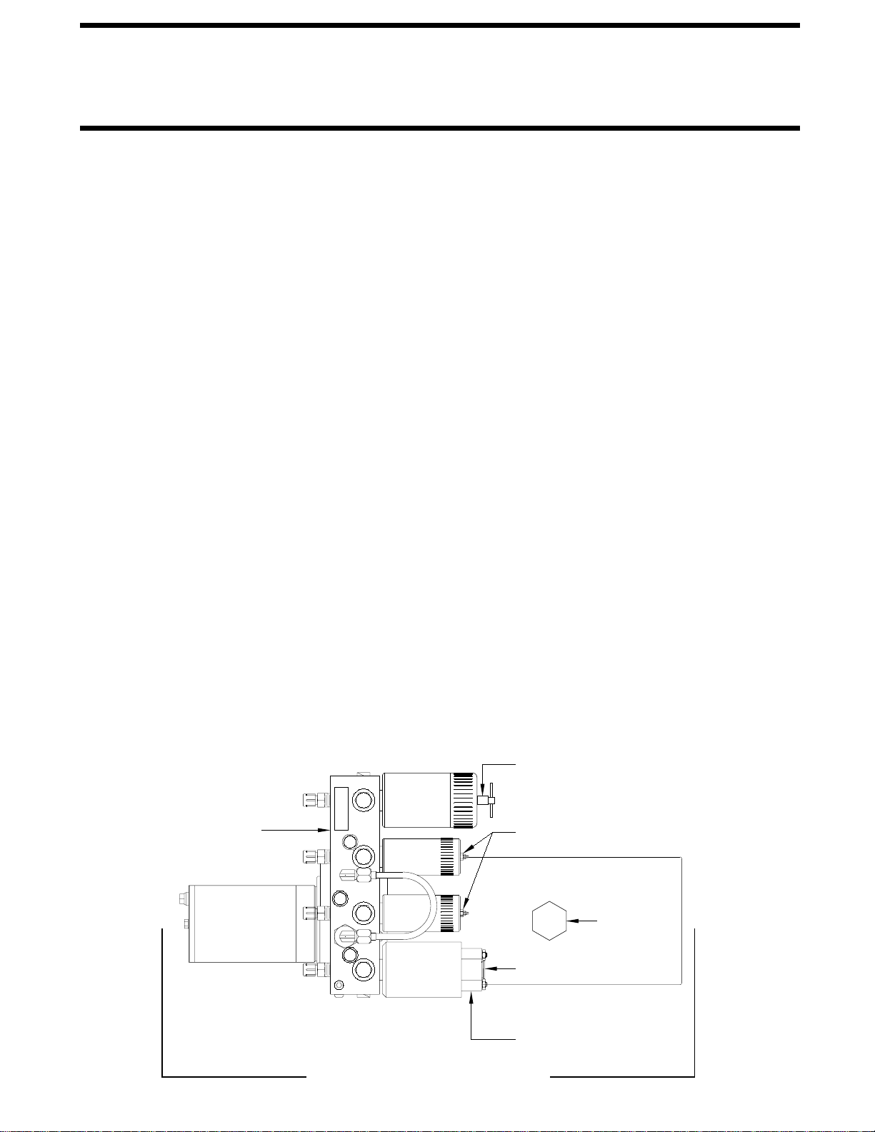
SENSING UNIT - TOP VIEW
D
C
A
B
LED’S - LOCATION
CONTROL BOX - SIDE VIEW
MAY BE DIFFERENT
NOT IN PARK/BRAKE CHECK
Set the park/brake. Switch the ignition to the "ACC" or "ON"
position. Push the "ON/OFF" switch toward "ON". Release
the parking brake and confirm that the "PARK" indicator light
comes on. Reset the parking brake. The "PARK" indicator
light should go out. Switch the ignition to "OFF".
THE COACH WHEELS SECURELY SO THE COACH
CANNOT ROLL FORWARD OR BACKWARD.
CAUTION: WHEN MAKING THIS CHECK, BLOCK
If any of the above checks or inspections reveal a problem
or if there are other problems or questions, consult a
qualified RV repair center, your vehicle or coach
manufacturer, or HWH CORPORATION for service or repair.
07MAR07
MP44.1501
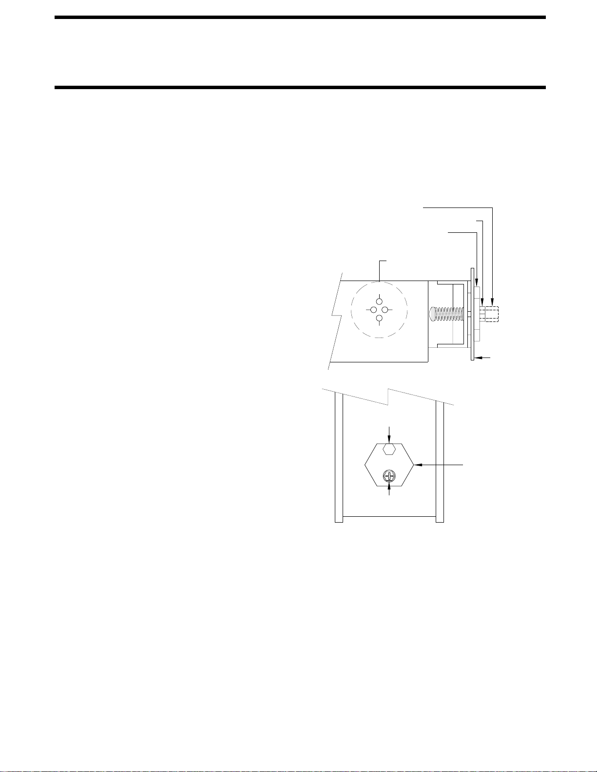
ADJUSTMENT
NUT (7/8" or 3/4")
BOX WALL
CONTROL
SCREW (Phillips or 1/4")
ADJUSTMENT
NUT (5/16")
ADJUSTMENT
SENSING UNIT ADJUSTMENT
adjustments first, then hold the adjustment nut from moving
while making the A-C adjustment.
wrench and a philips screw driver will be needed.
needed. A 7/8", 3/4" or 5/16" socket w/driver or box end
Touch Panel, manual adjustments to the Sensing Unit are
properly adjusted. If there are yellow LEVEL lights lit on the
are no yellow lights lit on the Touch Panel, the sensing unit is
With the vehicle level according to the bubble level, if there
Control Box. If two LED’s are on, it is best to make the B-D
be a problem with the Sensing Unit or the mounting of the
be turned more than 3/4 turn to turn the LED out, there may
to be turned more than 1/2 flat or the adjustment screw has to
screw will turn out LED’s A and C. If the adjustment nut has
the adjustment nut to turn out LED’s B and D. The adjustment
to the drawing below. The Sensing Unit is adjusted by turning
There are four LED’s on the Sensing Unit, A,B,C and D. Refer
Control Box is mounted to the power unit/valve assembly.
The Sensing Unit is mounted inside the Control Box. The
level the vehicle until the bubble is centered.
level, ignoring the yellow LEVEL lights on the Touch Panel,
that is to be level. Using the Leveling System and the bubble
the freezer floor or upon whichever surface within the vehicle
Level the vehicle by placing a bubble level in the center of
the vehicle, the front is still low. This means the front
"tweaking" process until the system levels the vehicle
touch panel. Recheck with a level. Repeat the
relevel the vehicle using the yellow level lights on the
the front up more. Again, unlevel the vehicle then
the front yellow light to stay on slightly longer to bring
instructions for LED’s A, B, C, and D. This will allow
the OPPOSITE direction that is given in the above
Move the adjustment for that light very, very, slightly in
which sensing unit light is the front light, A-B-C or D.
yellow level light is turning off too soon. Determine
properly.
Example: After the initial adjustment and releveling
sensing unit, ignoring the LED’s on the sensing unit.
yellow level lights go out, instead just "tweak" the
needed, DO NOT try to adjust the sensing unit until the
LEVEL lights. Recheck the level. If more adjustment is
lights are on. Level the vehicle according to the yellow
vehicle to an unlevel position so one or two yellow
IMPORTANT: When all 4 LED’s are off, move the
If LED (D) is lit: Turn the adjustment nut CLOCKWISE
If LED (B) is lit: Turn the adjustment nut COUNTER
If LED (C) is lit: Turn the adjustment screw CLOCKWISE
If LED (A) is lit: Turn the adjustment screw COUNTER
NOTE: If opposing LED’s are lit, there is a problem with
until the LED is off.
CLOCKWISE until the LED is off.
until the LED is off.
CLOCKWISE until the LED is off.
the Sensing Unit.
ADJUSTMENT NUT (7/8" or 3/4")
ADJUSTMENT SCREW (Phillips or 1/4")
ADJUSTMENT NUT (5/16")