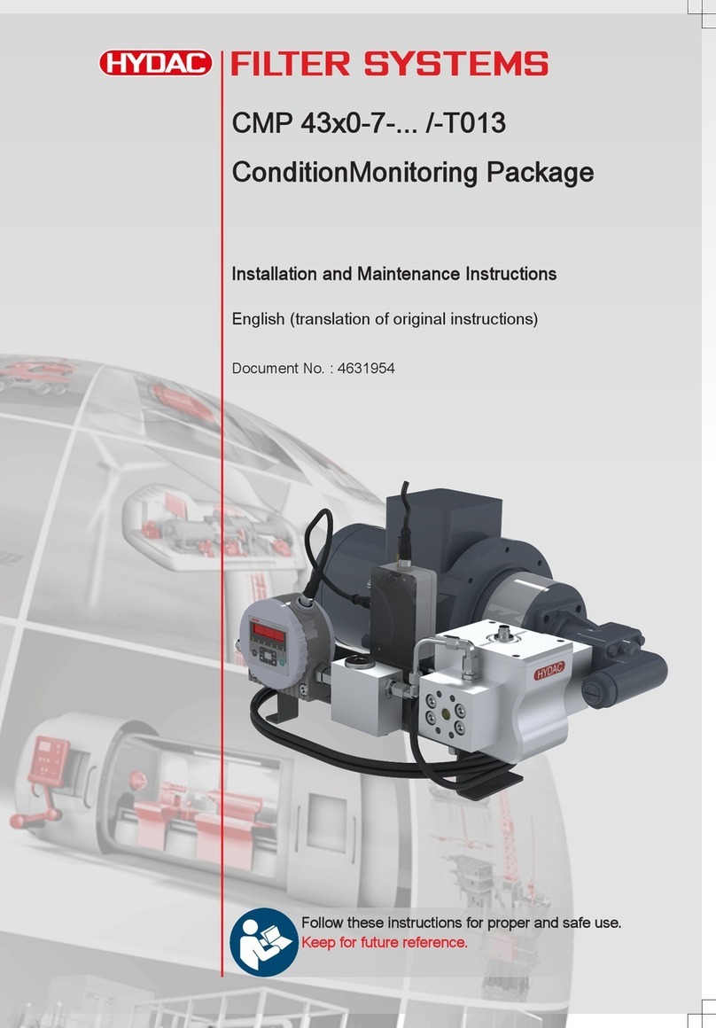
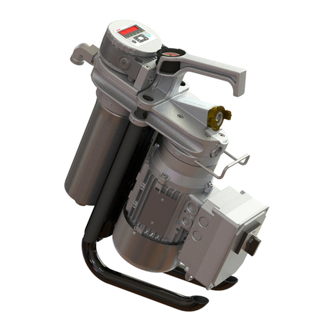
Hydac PTK Series Manual

Pumpenträger mit
Öl-Luft-Kühler PTK
Betriebs- und Wartungsanleitung
Bell housing with
oil-air cooler PTK
Operating and Maintenance Instructions
Support de pompe avec
refroidisseur air-huile PTK
Mise en service et entretien
D/E/F 5.601.B.6/11.15

2
D/E/F 5.601.B.6/11.15
INHALT
1. SICHERHEITSHINWEIS
1.1 KENNZEICHNUNG VON
HINWEISEN
1.2 PERSONALQUALIFIKATION
UND -SCHULUNG
1.3 GEFAHREN BEI
NICHTBEACHTUNG DER
SICHERHEITSHINWEISE
1.4 SICHERHEITSBEWUSSTES
ARBEITEN
1.5 SICHERHEITSHINWEISE FÜR
WARTUNGS-, INSPEKTIONS-
UND MONTAGEARBEITEN
1.6 EIGENMÄCHTIGER
UMBAU UND
ERSATZTEILHERSTELLUNG
1.7 UNZULÄSSIGE
BETRIEBSWEISEN
2. VERWENDUNGSZWECK
2.1 ZULÄSSIGE
KÜHLFLÜSSIGKEITEN
2.2 ZULÄSSIGE
VERSCHMUTZUNG DER
KÜHLFLÜSSIGKEITEN
2.3 ZULÄSSIGER
BETRIEBSDRUCK IM
KÜHLELEMENT
3. TYPENSCHLÜSSEL
4. TECHNISCHE DATEN
5. MONTAGE
6. ABMASSE
7. HYDRAULISCHER
ANSCHLUSS
8. VERSCHRAUBUNGS-
ELEMENTE
9. INBETRIEBNAHME
9.1 STILLSETZUNG DES PTK
10. WARTUNG
11 TRANSPORT UND
ZWISCHENLAGERUNG
11.1 TRANSPORT
11.2 ZWISCHENLAGERUNG
12. STÖRUNG / URSACHE UND
BESEITIGUNG
CONTENTS
1. SAFETY INFORMATION
1.1 KEY TO SAFETY SYMBOLS
1.2 STAFF QUALIFICATION AND
TRAINING
1.3 RISKS INVOLVED IF THE
SAFETY INFORMATION IS
NOT OBSERVED
1.4 SAFE WORKING PRACTICE
1.5 SAFETY INSTRUCTIONS
FOR MAINTENANCE,
INSPECTION AND
INSTALLATION WORK
1.6 UNAUTHORISED
MODIFICATIONS AND SPARE
PARTS
1.7 IMPROPER OPERATION
2. APPROPRIATE USE
2.1 PERMISSIBLE COOLANTS
2.2 PERMISSIBLE
CONTAMINATION OF THE
COOLANTS
2.3 PERMISSIBLE OPERATING
PRESSURE IN COOLER
ELEMENT
3. TYPE CODE
4. TECHNICAL
SPECIFICATIONS
5. MOUNTING
6. DIMENSIONS
7. HYDRAULIC CONNECTION
8. THREADED CONNECTIONS
9. COMMISSIONING
9.1 DECOMMISSIONING THE PTK
10. MAINTENANCE
11 TRANSPORT AND
TEMPORARY STORAGE
11.1 TRANSPORT
11.2 TEMPORARY STORAGE
12. FAULTS / CAUSES AND
ELIMINATION
CONTENU
1. CONSIGNES DE SÉCURITÉ
1.1 SYMBOLISATION DES
CONSIGNES
1.2 QUALIFICATION ET
FORMATION DU PERSONNEL
1.3 DANGERS EN CAS DE NON-
RESPECT DES CONSIGNES
DE SÉCURITÉ
1.4 TRAVAIL EN TOUTE
SÉCURITÉ
1.5 CONSIGNES DE SÉCURITÉ
POUR LES TRAVAUX
DE MAINTENANCE,
D'INSPECTION ET DE
MONTAGE
1.6 MODIFICATION ET
FABRICATION ARBITRAIRE
DE PIÈCES DE RECHANGE
1.7 PROCÉDURES NON
AUTORISÉES
2. CONDITIONS D'UTILISATION
2.1 FLUIDES DE
REFROIDISSEMENT
AUTORISÉS
2.2 POLLUTION ADMISSIBLE
DES FLUIDES DE
REFROIDISSEMENT
2.3 PRESSION DE
SERVICE ADMISSIBLE
DANS L'ÉLÉMENT DE
REFROIDISSEMENT
3. CODE DE COMMANDE
4. CARACTÉRISTIQUES
TECHNIQUES
5. MONTAGE
6. DIMENSIONS
7. RACCORDEMENT
HYDRAULIQUE
8. ELÉMENTS DE VISSAGE
DANS LE CIRCUIT D'HUILE
9. MISE EN SERVICE
9.1 MISE À L'ARRÊT DU PTK
10. MAINTENANCE
11 TRANSPORT ET
ENTREPOSAGE
11.1 TRANSPORT
11.2 ENTREPOSAGE
12. PANNES / CAUSES ET
SOLUTIONS
Das Technisches Datenblatt
kann bei Bedarf von
HYDAC International GmbH
angefordert werden.
Bitte HYDAC Artikelnummer und
Typenbezeichnung angeben !
HYDAC
INTERNATIONAL GmbH
Industriegebiet
D-66280 Sulzbach / Saar
Tel.:+49 (0) 6897/509-01
Fax: +49 (0) 6897/509-577
If required, the technical data sheet
is available from
HYDAC International GmbH.
Please give HYDAC part number
and type code !
HYDAC
INTERNATIONAL GmbH
Industriegebiet
D-66280 Sulzbach / Saar
Tel.:+49 (0) 6897/509-01
Fax: +49 (0) 6897/509-577
En cas de besoin, la société
HYDAC International GmbH
peut demander la che technique
de l'installation.
Veuillez communiquer à HYDAC le code
article et la désignation du type !
HYDAC
INTERNATIONAL GmbH
Industriegebiet
D-66280 Sulzbach / Saar
Tel.:+49 (0) 6897/509-01
Fax: +49 (0) 6897/509-577

D/E/F 5.601.B.6/11.15
3
WARENZEICHEN
Die verwendeten Warenzeichen
anderer Firmen bezeichnen
ausschließlich die Produkte dieser
Firmen.
COPYRIGHT © 2006 BY
HYDAC INTERNATIONAL GMBH.
ALL RIGHTS RESERVED
Alle Rechte vorbehalten. Nachdruck
oder Vervielfältigung dieses
Handbuchs, auch in Teilen, in
welcher Form auch immer, ist
ohne ausdrückliche schriftliche
Genehmigung von HYDAC nicht
erlaubt. Zuwiderhandlungen
verpichten zu Schadenersatz.
HAFTUNGSAUSSCHLUSS
Wir haben unser Möglichstes getan,
die Richtigkeit des Inhalts dieses
Dokuments zu gewährleisten, dennoch
können Fehler nicht ausgeschlossen
werden. Deshalb übernehmen wir
keine Haftung für Fehler und Mängel
in diesem Dokument, auch nicht für
Folgeschäden, die daraus entstehen
können.
Die Angaben dieser Druckschrift
werden regelmäßig überprüft, und
notwendige Korrekturen sind in den
nachfolgenden Auagen enthalten.
Für Verbesserungsvorschläge sind wir
dankbar.
Technische Änderungen dieses
Handbuchs behalten wir uns ohne
Ankündigung vor.
TRADEMARKS
Where trademarks of other companies
are used, these relate only to those
companies' products.
COPYRIGHT © 2006 BY
HYDAC INTERNATIONAL GMBH.
ALL RIGHTS RESERVED
All rights reserved. This manual may
not be reproduced in part or whole in
whatever form without the explicit written
agreement of HYDAC. Contraventions
are liable to compensation.
EXCLUSION OF LIABILITY
We have used our best endeavours to
ensure the accuracy of the contents of
this document. However, errors cannot
be ruled out. Consequently, we accept no
liability for such errors as may exist in this
document, nor for any consequential loss.
The content of this manual is checked
regularly. Any corrections required will
be incorporated in subsequent editions.
We welcome any suggestions for
improvements.
This manual is subject to technical
modications without prior notice.
MARQUES
Les marques d'autres entreprises
utilisées ici se réfèrent exclusivement aux
produits de ces entreprises.
COPYRIGHT © 2006 BY
HYDAC INTERNATIONAL GMBH.
ALL RIGHTS RESERVED
Tous droits réservés. Toute ré-impression
ou reproduction, même partielle, de ce
manuel est interdite, sous quelque forme
que ce soit, sans l'autorisation écrite
expresse d'HYDAC. Le manquement
à cette condition donnera lieu à des
dommages - intérêts.
EXCLUSION DE GARANTIE
Nous avons fait tout notre possible pour
garantir l'exactitude des informations
contenues dans ce document.
Néanmoins, il est impossible d'exclure
une erreur. Aussi n'assumons-nous
aucune responsabilité pour les erreurs et
les déciences de ce document, ainsi que
pour les dommages consécutifs pouvant
en découler.
Les informations contenues dans ce
manuel sont régulièrement vériées et les
corrections nécessaires sont intégrées
aux éditions ultérieures. Veuillez nous
faire part de vos souhaits d'amélioration.
Nous nous réservons le droit de modier
sans préavis le contenu du présent
manuel.
4
D/E/F 5.601.B.6/11.15
1. SICHERHEITSHINWEISE
Diese Betriebs- und Wartungsanleitung enthält grundlegende
Hinweise, die bei Installation, Betrieb und Wartung zu beachten
sind. Sie ist daher unbedingt vor Montage und Inbetriebnahme vom
Monteur sowie dem zuständigen Fachpersonal/Betreiber zu lesen.
Sie muss ständig am Einsatzort der Anlage verfügbar sein.
Diese Betriebs- und Wartungsanleitung bezieht sich auf den
Pumpenträger mit Öl-Luft Kühler PTK-XXX/M/XXX...
Es sind nicht nur die unter diesem Abschnitt "Sicherheitshinweise"
aufgeführten, allgemeinen Sicherheitshinweise zu beachten, sondern
auch die unter den anderen Abschnitten eingefügten, speziellen
Sicherheitshinweise.
1.1. KENNZEICHNUNG VON HINWEISEN
Die in dieser Betriebs- und Wartungsanleitung enthaltenen
Sicherheitshinweise, die bei Nichtbeachtung Gefährdung für
Personen hervorrufen können, sind mit Allgemeinem Gefahrensymbol
"Sicherheitszeichen nach DIN 4844" besonders gekennzeichnet.
Dieses Symbol nden Sie bei Sicherheitshinweisen, deren
Nichtbeachtung Gefahren für die Maschine und deren Funktionen
hervorrufen kann.
Hier stehen Ratschläge oder Hinweise, die das Arbeiten erleichtern
und für einen sicheren Betrieb sorgen.
Direkt am PTK angebrachte Hinweise wie z.B.
zDrehrichtungspfeil
zMontagevorschrift Kühlelement
müssen unbedingt beachtet und in vollständig lesbarem Zustand
gehalten werden.
1.2. PERSONALQUALIFIKATION UND -SCHULUNG
Das Personal für Bedienung, Wartung, Inspektion und Montage muss
die entsprechende Qualikation für diese Arbeiten aufweisen.
Verantwortungsbereich, Zuständigkeit und die Überwachung des
Personals müssen durch den Betreiber genau geregelt sein.
1.3. GEFAHREN BEI NICHTBEACHTUNG DER SICHERHEITSHINWEISE
Die Nichtbeachtung der Sicherheitshinweise kann sowohl eine
Gefährdung für Personen als auch für die Umwelt und Anlage zur
Folge haben. Die Nichtbeachtung der Sicherheitshinweise kann zum
Verlust jeglicher Schadenersatzansprüche führen.
Im Einzelnen kann Nichtbeachtung beispielsweise folgende
Gefährdungen nach sich ziehen:
zVersagen wichtiger Funktionen der Anlage
zVersagen vorgeschriebener Methoden zur Wartung
und Instandhaltung
zGefährdung von Personen durch elektrische und
mechanische Einwirkungen
1.4. SICHERHEITSBEWUSSTES ARBEITEN
Die in dieser Betriebs- und Wartungsanleitung aufgeführten
Sicherheitshinweise, die bestehenden nationalen Vorschriften zur
Unfallverhütung sowie eventuelle interne Arbeits-, Betriebs- und
Sicherheitsvorschriften des Betreibers sind zu beachten.
HINWEIS
ACHTUNG
D

D/E/F 5.601.B.6/11.15
5
1.5 SICHERHEITSHINWEISE FÜR WARTUNGS-, INSPEKTIONS- UND
MONTAGEARBEITEN
Der Betreiber hat dafür zu sorgen, dass alle Wartungs-, Inspektions- und
Montagearbeiten von autorisiertem und qualiziertem Fachpersonal
ausgeführt werden, welches sich durch eingehendes Studium der
Montage- und Betriebsanleitung ausreichend informiert hat.
Grundsätzlich sind Arbeiten am PTK nur im Stillstand und mit
unterbrochener Stromzufuhr durchzuführen.
Die in der Betriebs- und Wartungsanleitung beschriebene
Vorgehensweise zum Stillsetzen (siehe 9.1) des PTK muss unbedingt
eingehalten werden.
Unmittelbar nach Abschluss der Arbeiten müssen alle Sicherheits-
und Schutzeinrichtungen wieder angebracht bzw. in Funktion gesetzt
werden.
Vor der Wiederinbetriebnahme sind die im Abschnitt
9. "Inbetriebnahme" aufgeführten Punkte zu beachten.
1.6 EIGENMÄCHTIGER UMBAU UND ERSATZTEILHERSTELLUNG
Umbau oder Veränderungen am PTK sind nur nach Absprache mit
dem Hersteller zulässig.
Auf keinen Fall darf der Pumpenansch vom Gehäuse demontiert
werden.
Eine Demontage zerstört die Koaxialität und Parallelität des PTK.
Bei Nichtbeachtung werden Pumpenschäden, Kupplungsausfälle und
Motorschäden verursacht.
Originalersatzteile und vom Hersteller autorisiertes Zubehör dienen
der Sicherheit.
Die Verwendung anderer Teile kann die Haftung für die daraus
entstehenden Folgen aufheben.
1.7 UNZULÄSSIGE BETRIEBSWEISEN
Die Betriebssicherheit des gelieferten PTK ist nur bei
bestimmungsgemäßer Verwendung entsprechend Abschnitt
2. Verwendungszweck der Betriebs- und Wartungsanleitung
gewährleistet.
Die in den technischen Daten angegebenen Grenzwerte dürfen auf
keinen Fall überschritten werden.
2. VERWENDUNGSZWECK
Der PTK ist ein Verbindungselement zwischen Motor und
Hydraulikpumpe in Kombination mit einem Öl-Luft-Kühler.
2.1 ZULÄSSIGE KÜHLFLÜSSIGKEITEN
Mineralöl nach DIN 51524
Andere Medien auf Anfrage
Der PTK darf nicht mit feuergefährlichen Medien
z.B. Diesel und Brennstoff betrieben werden.
Alle Komponenten im Kühlkreislauf müssen
auf Medienverträglichkeit überprüft werden !
2.2 ZULÄSSIGE VERSCHMUTZUNG DER KÜHLFLÜSSIGKEITEN
Die verwendeten Medien müssen frei von abrasiven oder
langfaserigen Bestandteilen sein.
Partikelgröße < 0,6 mm (kugelförmig)
2.3 ZULÄSSIGER BETRIEBSDRUCK IM KÜHLELEMENT
Max. Betriebsdruck: 16 bar (dynamisch)
bei 2 Mio.Lastwechsel (2 Hz)
Druckspitzen, die über den genannten Betriebsdruck hinausgehen,
können zu Leckagen im Kühlelement führen.
ACHTUNG
D
ACHTUNG

6
D/E/F 5.601.B.6/11.15
PTK - 250 / M / 140 / FB092 - E / F3
Typ
PTK = Elastischer Pumpenträger
mit Öl-Luft-Kühler
Nenngröße für IEC Normmotor
Mineralölbeständigkeit
M = (siehe 2.1)
Pumpenträgerlänge N
Bohrbildcode für Pumpenanschluss
Ausführung Dämpfungsring
Zubehör
F3 = Pumpenträgerfuß
3. TYPENSCHLÜSSEL
4. TECHNISCHE DATEN
Die Kühlleistung ist abhängig vom Volumenstrom
(siehe Prospekt)
D
HINWEIS
5. MONTAGE
Die Einbaulage des PTK ist beliebig.
Der PTK muss so aufgestellt werden, dass die Kühlluft ungehindert
zu- und abströmen kann.
Der Anschluss vom Kühlelementeingang und -ausgang ist beliebig.
Bei der Montage des Lüfterrades muss die Nabe bis zum Anschlag
auf die Motorwelle geschoben werden.
Danach muss die Nabe durch Anziehen des Gewindstiftes gesichert
werden.
Bei Verwendung der Motorbauform V1 und V15 kann das Kühlelement
gedreht werden (siehe Skizze).
ACHTUNG
Tank
Montage Kühelement bei Verwendung der
Motorbauformen V1 und V3 Lüfterrad
Gewindestift
Anschluss Motor
Nabe
Wärmetauscher
Pumpen-
ansch
Anschluss
Pumpe
Dämpfungs-
ring
Klemmring

D/E/F 5.601.B.6/11.15
7
D
6. ABMASSE
Siehe Prospekt, technisches Datenblatt oder Auslegungssoftware.
7. HYDRAULISCHER ANSCHLUSS
Dimension der Kühlelementanschlüsse:
G3/4
(PTK-200/-250/-300/-350)
Hydraulische Anschlüsse müssen bei Montage bzw. Demontage der
Anschlussverschraubung am Kühlelementeingang bzw. -ausgang am
Sechskant, mit einem geeigneten Werkzeug gegengehalten werden.
(siehe Skizze)
Schutz des Kühlelementes gegen Verspannungen
Anschlüsse des Kühlelementes vor Drehmoment schützen:
M max. 40Nm
Anschlussleitungen (gehören nicht zum Lieferumfang) sind so zu
verlegen, dass weder Schwingungen, Spannungen oder Stöße das
Kühlelement beaufschlagen.
Die durch Gewindeanschlüsse vorgegebenen Leitungsquerschnitte
wenn möglich nicht reduzieren.
ACHTUNG
HINWEIS
8. VERSCHRAUBUNGSELEMENTE IM ÖLKREISLAUF
Zum Abdichten der Verschraubungen darf kein Teonband bzw.
Kleber verwendet werden, um Verschmutzungen des Kühlsystems zu
vermeiden.
Es sind nur Verschraubungen nach DIN3852-T11 Form E mit
Proldichtring einzusetzen.
ACHTUNG

8
D/E/F 5.601.B.6/11.15
9. INBETRIEBNAHME
Bei Inbetriebnahme müssen folgende Punkte beachtet werden:
a. Hydraulische Anschlüsse des Kühlsystems an den Kreislauf der zu
kühlenden Anlage (Maschine) anschließen. (siehe Punkt 7 und 8).
b. Drehrichtung des Lüfterrades überprüfen.
Falsche Drehrichtung des Lüfterrades
führt zur Verminderung der Kühlleistung!
Drehrichtung auf Pumpenwelle gesehen RECHTS!
(im Uhrzeigersinn)
c. Auf freien Durchuss der Ölleitungen achten!
d. Einheit nach dem Einschalten auf Leckage prüfen.
9.1 STILLSETZUNG DES PTK
zStromzufuhr unterbrechen.
zDas Medium in geeignete Behältnisse ablassen.
HINWEIS
ACHTUNG
D
10. WARTUNG
Der PTK ist weitgehend wartungsfrei.
Eine Aufstellung in staubhaltiger Umgebung erfordert eine
periodische Reinigung des Kühlelementes.
zDas Kühlelement ist durch Lösen der beiden
Befestigungsschrauben leicht zu demontieren.
zReinigen mit Pressluft entgegen der normalen Durchblasrichtung.
zZur Vermeidung von Beschädigungen am Kühlelement, die eine
Leistungsverminderung der Einheit zur Folge hätte, empehlt sich
die Reinigung mit einer weichen Bürste.
Weitere Hinweise siehe auch Punkt 1.6
HINWEIS
11. TRANSPORT UND ZWISCHENLAGERUNG
11.1 TRANSPORT
Der Transport des PTK muss fachgerecht erfolgen.
Beim Transport muss das Kühlelement entleert sein!
11.2 ZWISCHENLAGERUNG
Die Zwischenlagerung soll bei trockenen Verhältnissen erfolgen.
Das PTK muss gegen Eindringen von Verunreinigungen
geschützt sein.
ACHTUNG

D/E/F 5.601.B.6/11.15
9
D
12. STÖRUNGEN / URSACHEN UND BESEITIGUNG
Keine oder zu geringe Kühlleistung
Lüfterrad läuft unruhig und geräuschvoll
Ursache Beseitigung
z z
Beschädigung Austausch der Komponenten
Schlauchleitung auf Knickung und
Verstopfung untersuchen
Schlauchleitungsdimensionen
überprüfen
z z Ablagerungen am Lüfterrad Reinigen oder Austausch des
Lüfterrades
z
Falsche Drehrichtung
Ölfördermenge zu klei
2 Phasen der Stromzuführung
vertauschen
-Achtung:
Pumpendrehrichtung rechts
Ölfördermenge kontrollieren
z
Zu geringes bzw.
kein Luftvolumen
Luftzufuhr am Luftein- und Luftaustritt
überprüfen
Anlage überprüfen
zSchlechter Wärmeübergang im
Kühlelement
Kühlelement reinigen
(siehe Pkt. 10)
zÖlfördervolumen zu klein Ölfördermenge kontrollieren

10
D/E/F 5.601.B.6/11.15
IMPORTANT
E
INFORMATION
1. SAFETY INFORMATION
These Operating and Maintenance Instructions contain basic information
which must be observed when installing, operating and maintaining
the unit. It is absolutely necessary for the tter and specialist staff /
operator responsible to read these instructions before installation and
commissioning. Ensure that these instructions are always kept in the
immediate vicinity of the unit.
These Operating and Maintenance Instructions refer to the
Bell Housing with Oil/Air Cooler PTK-XXX/M/XXX...
It is not only the general safety information given in this "Safety
information" section which must be observed, but also the additional,
special safety information which is given in the other sections.
1.1. KEY TO SAFETY SYMBOLS
"Safety symbol to DIN 4844-W9": this general danger symbol indicates
the safety information contained in these Operating & Maintenance
Instructions which, if not observed, can endanger personal safety.
This symbol will be found where a failure to observe the safety information
can lead to damage to the unit and its function.
Where you see this sign, you will nd advice or information which will
assist your work and ensure safe operation.
Notices attached directly to the PTK, e.g.
zDirection of rotation arrow
zMounting instructions for cooler element
must always be observed and must be kept in a fully legible condition.
1.2. STAFF QUALIFICATION AND TRAINING
The operating, maintenance, inspection and tting staff must have the
appropriate qualication for these types of work.
The area of responsibility, competence and staff monitoring must be
carefully controlled by the user.
1.3. RISKS INVOLVED IF THE SAFETY INFORMATION IS IGNORED
Failure to observe the safety information can cause risks both to personal
safety as well as to the environment and the system. Failure to observe the
safety information can lead to the loss of any claims for compensation.
In particular, failure to observe the safety information can result in the
following risks, for example:
zFailure of important functions of the system
zFailure of specied methods of servicing and maintenance
zDanger to personnel through electric shock and mechanical injury
1.4. SAFE WORKING PRACTICE
The safety information given in these Operating and Maintenance
Instructions, the existing national regulations on accident prevention, as
well as any internal working, operating and safety regulations of the user,
must be observed.

D/E/F 5.601.B.6/11.15
11
E
1.5 SAFETY INFORMATION FOR MAINTENANCE, INSPECTION
AND INSTALLATION WORK
The operator must ensure that all maintenance, inspection and installation
work is carried out by authorized and qualied specialist staff, who are
sufciently informed by studying the Operating and Maintenance Instructions
thoroughly.
The PTK must always be switched off and disconnected from the power
supply before any work is carried out on it.
The procedure described in the Operating and Maintenance Instructions
for Decommissioning the PTK (see 9.1) must be strictly followed.
Immediately after the work has nished, all safety and protection devices
must be re-tted and put back in to operation.
Before re-commissioning, the points listed in Section 9. Commissioning
must be observed.
1.6 UNAUTHORISED MODIFICATION AND SPARE PARTS
Conversions or modications to the PTK are only permissible by
agreement with the manufacturer.
On no account should the pump ange be removed from the housing.
Dismantling will destroy the concentricity and parallelism of the PTK.
If this stipulation is not observed, damage will be caused to the pump and
motor and the coupling will fail.
Original spare parts and accessories authorised by the manufacturer are
required for safety reasons.
The use of other parts can invalidate the liability for the resulting
consequences.
1.7 IMPROPER OPERATION
The operational safety of the PTK supplied is only guaranteed for
appropriate use as per Section 2. Appropriate use of the Operating and
Maintenance Instructions.
The limits stated in the technical specications must never be exceeded.
2. APPROPRIATE USE
The PTK is a connecting element between motor and hydraulic pump in
combination with an oil/air cooler.
2.1 PERMISSIBLE COOLANTS
Mineral oil to DIN 51524
Other uids on request
The PTK must not be operated with ammable uids
e.g. diesel and fuel.
All components in the cooling circuit must be
checked for uid compatibility !
2.2 PERMISSIBLE CONTAMINATION OF THE COOLANTS
The uids used must be free of abrasive particles and long bres.
Particle size < 0.6 mm (spherical)
2.3 PERMISSIBLE OPERATING PRESSURE IN THE COOLER ELEMENT
Max. operating pressure: 16 bar (dynamic)
at 2 million cycles (2 Hz)
Pressure surges which exceed the stated operating pressure,
can cause leakage in the cooler element.
IMPORTANT
IMPORTANT

12
D/E/F 5.601.B.6/11.15
E
3. MODEL CODE
4. TECHNICAL SPECIFICATIONS
The cooling capacity is dependent on the ow rate
(see brochure)
5. INSTALLATION
The mounting position of the PTK is optional.
The PTK must be positioned so that the cooling air can
ow in and out freely.
The cooler element inlet and outlet connections can be selected by the
user.
When mounting the fan wheel, the collar must be pushed right to the end
of the motor shaft.
Then the collar must be secured by tightening the threaded pin.
If using motor construction types V1 and V15 the cooler element can
simply be turned (see diagram).
tank
Mounting of cooler element using
motor constructions V1 and V3 fan wheel
threaded pin
motor connection
collar
heat exchanger
pump
ange
pump
connection
damping
ring
clamping
ring
INFORMATION
IMPORTANT
PTK - 250 / M / 140 / FB092 - E / F3
Type
PTK = exible bell housing
with oil-air cooler
Nominal size for ICE standard motor
Mineral oil resistance
M = (see 2.1)
Bell housing length N
Bore template code for pump connection
Type of damping ring
Accessories
F3 = bell housing foot bracket

D/E/F 5.601.B.6/11.15
13
E
6. DIMENSIONS
See brochure, technical data sheet or design software.
7. HYDRAULIC CONNECTION
Dimension of the cooler element connection:
G3/4
(PTK-200/-250/-300/-350)
When mounting or dismantling the threaded connection of the cooler
element inlet or outlet, the torque must be counteracted at the hexagon
using a suitable tool
(see diagram)
To protect the cooler element from distortions
Protect the connections of the cooler element from the torque:
M max. 40Nm
Connecting lines (not supplied) must be such that any oscillations,
stresses or knocks do not affect the cooler element.
If possible do not reduce pipe cross-sections pre-determined by the
threaded connections.
8. THREADED CONNECTIONS IN THE OPERATING
FLUID CIRCUIT
The connections must not be sealed with Teon tape or adhesive,
to ensure ingress into the cooling system does not occur.
Only threaded connections to DIN3852-T11 Form E with prole seal ring
must be used.
IMPORTANT
INFORMATION
IMPORTANT

14
D/E/F 5.601.B.6/11.15
E
9. COMMISSIONING
When commissioning, the following points must be taken into
consideration:
a. Connect the hydraulic connections of the cooling system to the circuit of
the system (machine) to be cooled (see point 7 and 8).
b. Check direction of rotation of fan wheel.
If the fan wheel turns in the wrong direction,
it can reduce the cooling capacity !
Direction of rotation when looking at the pump shaft
CLOCKWISE !
c. Check there is free ow through the oil lines !
d. After switching unit on, check for leakage.
9.1 DECOMMISSIONING THE PTK
zDisconnect from the power supply.
zDrain the uid into suitable containers.
10. MAINTENANCE
The PTK is largely maintenance-free.
If installed in a very dusty environment, the cooler element must be
cleaned at regular intervals.
zThe cooler element can easily be removed by loosening
both mounting bolts.
zBlow through with compressed air against the normal air ow direction
zClean the cooler element using a soft brush to avoid damaging it.
Any damage would reduce the cooling capacity.
For further information, see also Point 1.6
11. TRANSPORT AND TEMPORARY STORAGE
11.1 TRANSPORT
The PTK must be transported correctly.
The cooler element must be drained before transporting!
11.2 TEMPORARY STORAGE
The unit must be stored in dry conditions.
Action must be taken to prevent contamination from entering the PTK .
IMPORTANT
INFORMATION
INFORMATION
IMPORTANT

D/E/F 5.601.B.6/11.15
15
E
12. FAULTS / CAUSES AND ELIMINATION
No cooling capacity (or too little)
Fan wheel not running smoothly, noisy
Cause Remedy
z z
Damage Replace components
Check hose for kinks and blockages
Check dimensions of hose
z z Foreign matter on fan wheel Clean or replace fan wheel
z
Incorrect direction of rotation
Insufcient oil ow
ranspose 2 phases of the electrical
supply
-Important:
Pump direction of rotation clockwise
Check oil ow rate
z
Air ow too low or
no air ow
Check air supply at the air inlet and
outlet
Check system
zPoor heat transfer in the cooler element Clean cooler element
(see Pt. 10)
zInsufcient oil ow Check oil ow rate

16
D/E/F 5.601.B.6/11.15
CONSEIL
ATTENTION
F
1. CONSIGNES DE SECURITE
Cette notice d'utilisation et de maintenance contient des consignes de
base qu'il convient de respecter lors de l'installation, du fonctionnement
et de la maintenance. Par conséquent, il est nécessaire que le montage
et le personnel qualié / l'exploitant la lise avant le montage et la mise en
service. Elle doit être constamment disponible sur le lieu d'utilisation de
l'installation.
Cette notice d'utilisation et de maintenance se réfère au support de pompe
avec refroidisseur air-huile PTK-XXX/M/XXX...
Il ne faut pas uniquement tenir compte des consignes de sécurité
générales présentées dans ce chapitre, mais aussi de celles présentées
dans les autres paragraphes.
1.1. SYMBOLISATION DES CONSIGNES
Les consignes de sécurité contenues dans cette notice d'utilisation et de
maintenance, qui peuvent provoquer, si elles ne sont pas respectées, des
dangers pour les personnes, sont caractérisées par un symbole de danger
général "symbole de sécurité selon DIN 4844".
Vous trouverez ce symbole pour les consignes de sécurité dont le non
respect peut provoquer des dangers pour la machine et ses fonctions.
Il y a ici des conseils ou indications qui facilitent le travail ou pourvoient à
un fonctionnement sûr.
Les indications présentées directement sur le PTK comme
zFlèche de sens de rotation
zPlan de raccordement électrique
zFluide compatible
doivent être impérativement respectées et toujours lisibles.
1.2. QUALIFICATION ET FORMATION DU PERSONNEL
Le personnel pour l'utilisation, la maintenance, l'inspection et le montage
doit présenter la qualication correspondant à ces travaux.
Le domaine de responsabilité, la compétence et l'observation du personnel
doivent être décrites exactement par l'exploitant.
1.3. DANGERS EN CAS DE NON RESPECT DES CONSIGNES DE SECURITE
Le non respect des consignes de sécurité peut avoir pour conséquences,
non seulement une mise en danger des personnes mais aussi pour
l'environnement et l'installation. Il peut également mener à une perte de
tout droit à des dommages et intérêts.
Plus précisément, le non respect peut par exemple provoquer les dangers
suivants:
zDéfaillance de fonctions importantes de l'installation
zDéfaillance des méthodes prescrites pour la maintenance et l'entretien
zMise en danger des personnes suite à des conséquences électriques et
mécaniques
1.4. TRAVAIL EN TOUTE SECURITE
Il faut respecter les consignes de sécurité présentées dans cette notice
d'utilisation et de maintenance, les réglementations nationales existantes
relatives à la prévention des accidents ainsi que les éventuelles
prescriptions internes de travaux, fonctionnement et sécurité de
l'exploitant.

D/E/F 5.601.B.6/11.15
17
F
1.5 CONSIGNES DE SECURITE POUR LES TRAVAUX DE MAINTENANCE,
D'INSPECTION ET DE MONTAGE
L'exploitant doit veiller à ce que tous les travaux de maintenance,
d'inspection et de montage soient être effectués par du personnel qualié et
autorisé qui s'est, grâce à une étude minutieuse du montage et de la notice
d'utilisation, sufsamment informé.
En général, les travaux sur le PTK ne doivent être effectués
que sur un appareil hors service.
La procédure décrite dans la notice d'utilisation et de maintenance
concernant l'arrêt pour entretien de l'installation (voir 9.1) doit être
scrupuleusement respectée. Immédiatement après l'arrêt des travaux,
tous les dispositifs de sécurité et de protection doivent être à nouveau
appliqués, le cas échéant mis en fonction. Il faut observer les points décrits
au paragraphe 9 Mise en service avant la remise en marche.
1.6 MODIFICATION ET FABRICATION ARBITRAIRE DE PIECES DE RECHANGE
Une transformation ou des modications sur le PTK ne sont permises
qu'après accord avec le constructeur.
La bride de la pompe ne doit en aucun cas être démontée du corps.
Un démontage endommage la co-axialité et la parallèlité du PTK.
En cas de non-respect, la pompe et le moteur peuvent subir des
dommages et des pannes pouvant impacter sur le coupleur du moteur.
Les pièces de rechange originales et les accessoires autorisées par
le fabricant garantissent la sécurité. L'utilisation d'autres pièces peut
suspendre la garantie pour les suites qui pourraient en découler.
1.7 PROCEDURES NON AUTORISEES
La sécurité de fonctionnement des installations livrées n'est garantie
que pour une utilisation conforme aux prescriptions correspondant au
paragraphe 2. Conditions d'utilisation gurant dans la notice de d'utilisation
et de maintenance. Les valeurs limites indiquées dans les données
techniques ne doivent en aucun cas être dépassées.
2. CONDITIONS D'UTILISATION
Le PTK est un élément de liaison entre le moteur et la pompe hydraulique
en relation avec un refroidisseur air-huile.
2.1 FLUIDES DE REFROIDISSEMENT AUTORISES
Huile minérale selon DIN 51524
Autres uides sur demande
Le PTK ne doit pas être exploité avec des médias inammables
comme le gasoil ou d'autres combustibles.
Il faut contrôler la compatibilité aux uides de tous les composants
du circuit de refroidissement !
2.2 POLLUTION ADMISSIBLE DES FLUIDES DE REFROIDISSEMENT
Les uides utilisés doivent être exempts de particules abrasives et à bres
longues.
Taille des particules < 0,6mm (sphériques)
2.3 PRESSION DE SERVICE ADMISSIBLE DANS L'ELEMENT
DE REFROIDISSEMENT
Pression de service max. : 16 bar (dynamique)
à 2 mio. de cycles (2 Hz)
Des pics de pression au-delà de la pression de service indiquée
peuvent provoquer des fuites dans l'élément de refroidissement.
ATTENTION
ATTENTION

18
D/E/F 5.601.B.6/11.15
F
3. CODE DE COMMANDE
4. CARACTERISTIQUES TECHNIQUES
La puissance de refroidissement dépend du débit
(voir prospectus)
CONSEIL
5. MONTAGE
Le sens de montage du PTK est indifférent.
Le PTK doit être placé de manière à ce que la circulation d'air de
refroidissement ne soit entravée, ni à l'entrée, ni à la sortie.
Le raccordement d'entrée et de sortie de refroidisseur est indifférent.
Lors du montage du ventilateur, faire avancer la clavette jusqu'en butée
sur l'axe du moteur.
Bloquer ensuite la clavette en resserrant la vis sans tête.
Dans le cas du moteur forme V1 ou V15, il suft de faire pivoter l'élément
de refroidissement (voir croquis).
ATTENTION
Tank
Montage de l'élément de refroidissement en
cas d'utilisation d'un moteur de forme V1 ou V2 Couvercle
Goupille
Raccord moteur
Clavette
Refroidisseur
air/huille
Bride
de la
pompe
Raccord
pompe
Anneau
d'amortissement
Anneau
de serrage
PTK - 250 / M / 140 / FB092 - E / F3
Exécution du support de pompe
PTK = support de pompe èlastique
avec refroidisseur air-huile
Taille nominale pour moteur IEC
Compatibilité à l'huile minérale
M = (voir 2.1)
Longueur du support de pompe N
Plan de perçage pour raccordement pompe
Exécution de l'anneau d'amortissement
Accessoires
F3 = pied support de pompe

D/E/F 5.601.B.6/11.15
19
F
6. DIMENSIONS
Voir prospectus, che technique ou logiciel de détermination.
7. RACCORDEMENT HYDRAULIQUE
Dimension du raccord de l'élément de refroidisseur:
G3/4
(PTK-200/-250/-300/-350)
Lors du montage ou du démontage des raccordements hydrauliques
vissés à l'entrée ou la sortie de l'élément du refroidisseur , veiller à bloquer
la clé six pans à l'aide d'un outil approprié.
(voir schéma)
protection de l'élément du refroidisseur contre les efforts importants
Protéger les raccords de l'élément du couple de raccordement :
M max. 40Nm
Les conduites de raccordement (non comprises à la livraison)
doivent être placées de manière à ce que l'élément ne subisse aucune
vibration, tension ou choc.
Si possible, ne pas réduire les diamètres de passage
des raccordements taraudés.
ATTENTION
CONSEIL
8. ELEMENTS DE VISSAGE DANS LE CIRCUIT D'HUILE
An d'éviter des pollutions dans le système de refroidissement, ne pas
utiliser de téon ou de colle pour assurer l'étanchéité des raccords.
Seuls des raccordements selon DIN3852-T11 Forme E avec joints souples
peuvent être utilisés.
ATTENTION

20
D/E/F 5.601.B.6/11.15
F
9. MISE EN SERVICE
Respecter les points suivants lors de la mise en service :
a. Raccorder les orices hydrauliques du système de refroidissement au
circuit de l'installation (machine) à refroidir (voir point 7 et 8.)
b. Contrôler le sens de rotation du ventilateur.
Un sens de rotation erroné du ventilateur
conduit à une réduction de la puissance de refroidissement !
Sens de rotation VERS LA DROITE en regardant l'axe de la pompe !
(sens anti-horaire)
c. Ne pas entraver le débit du uide !
d. Contrôler la présence de fuite après mise en service.
9.1 MISE A L'ARRET DU PTK
zCouper le courant.
zVidanger le uide dans les récipients appropriés.
CONSEIL
ATTENTION
10. MAINTENANCE
Le PTK ne demande pratiquement pas d'entretien.
Une forte pollution de l'air ambiant peut conduire à un
nettoyage de l'échangeur thermique.
zPour démonter l'échangeur thermique, il suft de desserrer les deux vis
à tête cylindrique.
zNettoyer à l'air comprimé dans la direction inverse du ux d'air
zNous recommandons le nettoyage à l'aide d'une brosse souple an
d'éviter des dommages sur l'élément qui conduiraient à une diminution
de la puissance de l'unité.
Voir aussi point 1.6 pour d'autres recommandations.
CONSEIL
11. TRANSPORT ET ENTREPOSAGE
11.1 TRANSPORT
Le transport du PTK doit s'effectuer horizontalement.
Lors du transport, l'élément du refroidisseur doit être vidangé !
11.2 ENTREPOSAGE
Le PTK doit être entreposé au sec et protégé contre la pénétration
d'impuretés.
ATTENTION
This manual suits for next models
3
Table of contents
Languages:
Other Hydac Industrial Equipment manuals

Hydac
Hydac FluidAqua Mobil FAM 15 User manual

Hydac
Hydac VMU Series Manual

Hydac
Hydac LVU-CD-40 Manual

Hydac
Hydac RFX User manual

Hydac
Hydac SBO Series User manual

Hydac
Hydac FluidAqua Mobil FAM 15 Manual

Hydac
Hydac CMP 43x0-7/-T013 Series User manual

Hydac
Hydac MCS1 T005 Series Quick start guide

Hydac
Hydac SK Series User manual

Hydac
Hydac IXU 1 Series Manual