Hydro AutoDose 1170 User manual

10094778 Rev B 11/10 © Hydro Systems Company, Inc. 2010 HydroSystemsCo.com Toll Free: 1.800.543.7184 1
This guide contains instructions for installing, programming, and troubleshooting
the AutoDose™ Dispensing System. Throughout the guide, the following icons are
used to indicate the model(s) to which each step pertains.
AutoDose™ Automatic Dispensing System
The AutoDoseTM is a battery or A/C-powered peristaltic pumping dispenser that runs automatically at preset times as
programmed with an electronic timer / control. Product operates reliably and consistantly, even in demanding environments.
!
Please use this equipment carefully and
observe all warnings and cautions.
ALWAYS observe safety and handling instructions of
the chemical manufacturers.
ALWAYS direct discharge away from you or other
persons or into approved containers.
ALWAYS dispense cleaners and chemicals in accordance
with manufacturer’s instructions. Exercise CAUTION
when maintaining your equipment.
KEEP equipment clean for proper operation.
WEAR protective clothing and eyewear when working
in the vicinity of all chemicals, filling or emptying
equipment, or changing tubes.
ALWAYS re-assemble equipment according to
instruction procedures. Be sure all components are
firmly screwed or latched into position. Ensure that
hoses and electrical wires are properly placed and not
kinked or pinched.
ONLY USE ALKALINE BATTERIES.
Tube life will vary depending on the type of treatment
product used. To prevent emergency service, schedule
replacement at least once per year.
NOTE: The batteries should be scheduled for periodic
replacement. Using a total of 40 running (pumping)
hours, create a schedule for servicing the unit and
changing the batteries. Maintaining the power source
as such will help to provide the proper dosing by
providing a more consistent pumping rate.
Models:
Mounts:
Power:
Pail Mount
(3.5 – 5 gal pail)
8 D-cell batteries
Wall Mount
8 D-cell batteries
Wall Mount
A/C Power or 8 D-cell batteries
1170 1180 1190
AutoDose™ Dispenser Specifications:
PUMP
Flow Rate Approx 3.5 oz / min
Tube Material EPDM
Inlet Vacuum 20+ in Hg
Outlet Pressure 20 psi
SYSTEM CABINET
Material Polypropylene and ABS
Size (Model 1170) Approx. 7 3/4” tall X 14” diameter
(does not include container 1170 model system sits on)
Size (Models 1180 and 1190) 4 3/4” X 6 3/4” X 8 1/3”
PROGRAMMABLE TIMER / CONTROL
Program Duration Daily / Weekend / Week Days/Special
Maximum # of Events 24
Dispense Amount per Event 1 oz – 30 oz (dispensed in 1 oz increments)
or 30 – 900 ml (dispensed in 30 ml increments)
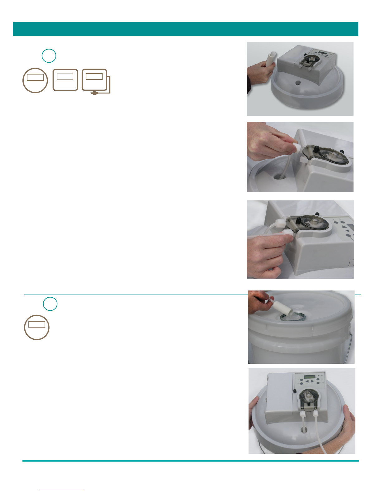
This package should contain:
• One AutoDoseTM dispenser
INSTALL PACKAGE CONTAINING:
• Ceramic weight and strainer for inlet tubing
• Polyethylene tubing (10 ft)
• Cable ties
• Mounting Bracket (Some Models)
• AC Adapter (Some Models)
• Injection Fitting

10094778 Rev B 11/10 © Hydro Systems Company, Inc. 2010 HydroSystemsCo.com Toll Free: 1.800.543.7184 2
STEP : Install the Batteries
1A
1170 1180
a. Loosen the battery door screw.
b. Open the battery compartment.
c. Place eight, fresh alkaline D-cell batteries into the holder as shown in the battery
compartment—and in the diagram on right.
Battery life is typically 40 running hours. A “low battery” indicator will alert you to a low voltage
condition indicating battery change. Program settings will be maintained if dispenser is
disconnected from power source.
STEP : Mount the Dispenser
1B
For Models 1180 and 1190, you’ll need to mount the dispenser before attaching the power
cord (if supplied).
a. Choose a location near the pipe or grease trap into which it will be dosing. In kitchens, the
unit may be mounted beneath the dish machine work tables or on the wall.
b. Use the mounting bracket to mark the appropriate locations for the mounting hardware.
c. Drill the holes accordingly and insert the anchors (if necessary) and screws provided.
d. Affix the mounting bracket to the wall.
e. Mount the dispenser onto the mounting bracket.
f. Secure the dispenser with the remaining screw provided.
Installation
Upper Level Placement
1180 1190
Lower Level Placement
+
+
+
+
+
+
+
+

10094778 Rev B 11/10 © Hydro Systems Company, Inc. 2010 HydroSystemsCo.com Toll Free: 1.800.543.7184 3
Installation
For certain models, either batteries or a 12v DC adapter may be used.
For the model 1190, use only the adapter specified from the manufacturer to ensure proper
operation.
NOTE: Usage of AC adapter must conform to local laws and codes.
a. Locate the jack on the side of the unit.
b. Install the adapter plug into the jack.
c. Plug the adapter into the wall receptacle.
CAUTION/CUIDADO:
Wires left hanging loose may be a tripping hazard, or may accidentally cause the adapter
to become unplugged.
STEP : Determine Appropriate Dispenser Location
2
For Model 1170, choose a location away from traffic. Bumping the dispenser may knock it over if the pail is
almost empty.
For Models 1180 and 1190, please refer to step 1B on page 2 for guidelines on determining the appropriate
dispenser location.
1170
1180
STEP : Install the Power Cord (if included)
1C
1190
1190

10094778 Rev B 11/10 © Hydro Systems Company, Inc. 2010 HydroSystemsCo.com Toll Free: 1.800.543.7184 4
STEP : Install the Inlet and Discharge Tubing
3
a. From the tubing supplied, cut a section long enough to reach from the pump
inlet (left side port) to the bottom of the pail to be used. Slide the ceramic
weight onto the end and insert the strainer into the end of the tube.
b. Route the tube properly and insert into the inlet compression fitting.
c. Hand tighten the nut to secure.
d. Connect remaining tubing to the exit side port and tighten.
e. Route and secure the tubing with cable ties provided so that the product is
dispensed directly into the intended drain to be treated.
f. If connecting to an existing facility drain piping, drill and tap the drain pipe or
trap cover for the 1/8” NPT injection fitting supplied. When the product should
be dispensed into a trap, but the trap is inaccessible, feed the tubing down the
inlet pipe to the trap. In these cases, the fitting can be drilled through to allow
the tubing to pass into the pipe. Wrap the injection fitting once with sealing
tape or thread compound and screw in the injection fitting. Tighten to provide a
positive seal.
NOTE: Be sure the tubing will be out of the way of traffic and will not impede motion
required in the area. Creating a low place in the run of tubing near the fitting will minimize
drainage from the tubing.
STEP : Prepare/Prime the Dispenser for Use
4
1170
a. Open the container of treatment product.
b. Drop the strainer end of the inlet tube into the container.
c. Place the dispenser on the container (for Model 1170).
d. Prime the pump: Press ENTER to wake the display and push and
hold the Prime button until product is evident at exit to drain.
e. Review the program and adjust if necessary.
Installation
1170 1180 1190

10094778 Rev B 11/10 © Hydro Systems Company, Inc. 2010 HydroSystemsCo.com Toll Free: 1.800.543.7184 5
12:00 am
PRIME
PROGRAM
ENTER
BACK
+
_
LOW
BATTERY
User Interface Definition
12:00 am
PRIME
PROGRAM
ENTER
BACK
+
_
LOW
BATTERY
Use ENTER to view or change
the data for that option.
ENTER is also used to save data.
LCD Display
Use FORWARD/BACKWARD to
increase or decrease options in each menu setting.
Use BACK to view previous
menu.
The user can view and program settings
on the device.
The LOW BATTERY indicator will
illuminate when battery life is low.
Use the PRIME button to prime the pump.
• Press ENTER.
• Press PROGRAM.
• Press ENTER to step through settings.
Reviewing Set Program
NOTE: To conserve power, the display will not be visible during normal operation.

10094778 Rev B 11/10 © Hydro Systems Company, Inc. 2010 HydroSystemsCo.com Toll Free: 1.800.543.7184 6
Unlocking Device
• Press ENTER to wake controller.
• Press PROGRAM and hold for 2 seconds.
• Press ENTER twice and enter PIN, using using +
_ to change each
number, then press ENTER to move to the next number.
NOTE: The default password is 0000. You will have an opportunity to
customize the pin in a later step.
• After the 4th number has been entered, press ENTER, and the system will
validate the number.
• If the number is correct, the user will enter Program Mode. If incorrect,
“INVALID” will appear on the display and the unit will exit programming
mode.
• When entering programming mode, the Low Batt LED will flash rapidly to
signify that the device is momentarily inactive during programming.
• Press ENTER to set hours.
• Press ENTER and set hours. Use +
_
to adjust hours.
• Press ENTER to set minutes. Use +
_
to adjust minutes.
• Press ENTER to save and continue with day.
• Use +
_
to adjust the day.
• Press BACK to edit hours if needed.
Setting Time/Day
ENTER USER PIN
0000
INVALID
12:00
TIME/DAY
12:00
SUN
___
___
_____
_

10094778 Rev B 11/10 © Hydro Systems Company, Inc. 2010 HydroSystemsCo.com Toll Free: 1.800.543.7184 7
• Press ENTER to begin setting the dispense units.
• Select OZ or ML.
• The dispense amount applies to the amount of chemical dispensed each time
the Drain Treater is scheduled to run.
• Program dispense amount.
• Use +
_
to adjust the amount in 1 oz. steps (units can be changed to
mL in a different menu).
• Press ENTER to begin setting the dispense Dispense Days.
• Use +
_to pick a preset number of days, or choose “SPECIAL” to
program each day individually.
• “DAILY” applies to every day of the week.
• “WEEKDAYS” applies to Mon-Fri.
• “WEEKENDS” applies to Sat-Sun.
• “SPECIAL” applies to a unique set of days during the week.
• Press ENTER to save and go to the next menu option.
Note: When using “SPECIAL” to select a particular day to program, deselect the
days not desired using ENTER to navigte Sunday through Saturday.
Program Dispense Days
DAILY
WEEKDAYS
WEEKENDS
SPECIAL
SUN Y?
Program Dispense Units
1 OZ
DISPENSE AMOUNT
DISPENSE UNITS
OZ ML
SAT Y?
_
___
_
_
DISPENSE DAYS

10094778 Rev B 11/10 © Hydro Systems Company, Inc. 2010 HydroSystemsCo.com Toll Free: 1.800.543.7184 8
• Press ENTER to begin setting the Dispense Times.
• Event 1 (up to 24 total) will automatically be selected. If acceptable, press
ENTER to accept and move to event 2.
• Press ENTER to begin with setting the hours. Use +
_ to adjust the
number up and down. The AM/PM function will automatically change.
• Press ENTER to save and continue with minutes.
• Minutes will be in increments of 10 minutes.
Continue programming events as needed remembering each event will
dispense the amount selected earlier. When finished, press PROGRAM when
next event is displayed. Press ENTER at “Done ? Y.”
NOTE: To eliminate an event, reprogram desired events, then when “EVENT N”
is visible, exit by pressing PROGRAM, and then ENTER to exit programming as
normal. Review programming and EVENT N to EVENT 24 will show “NONE.”
• Press ENTER to begin entering PIN.
• Use +
_ to change each number, then press ENTER to move to the
next number.
• After the 4th number, press ENTER to save and complete programming.
The time of day should be displayed.
NOTE: Controller will “go to sleep” after 30 seconds and display will be blank
until awakened by pressing ENTER.
Program User PIN
Program Dispense Times
DISPENSE TIMES
EVENT 1
12:00 am
12:15 am
EVENT N
DONE Y?
STORED
NEW PIN Y
USER PIN
N
ENTER PIN
0000
___
___
—
_
_
—

10094778 Rev B 11/10 © Hydro Systems Company, Inc. 2010 HydroSystemsCo.com Toll Free: 1.800.543.7184 9
Maintenence: Changing the Pump Tubing
NOTE: You may want to work over old newspapers or other discardable material to
protect floors or other areas from the possibility of spilled treatments.
Remove the Old Tubing
a. Loosen and remove tubing from compression fittings.
b. Loosen screw on pump cover and remove.
c. Lay aside the supply and discharge tubing.
d. Remove the old squeeze tube assembly from pump housing and discard it.
NOTE: If drain treatment leaks on pump housing, it can be washed in soapy water. If
the rotor assembly has been wetted, wipe it with a dry cloth. It is not necessary to
wipe the grease from the pump housing if the grease is clean.
Inspect the Pump
a. While the pump is disassembled, inspect all parts for foreign matter.
b. Clean the parts as necessary.
c. Check the rollers to ensure they turn freely.
d. Inspect the rotor.
CAUTION/CUIDADO:
If the rotor needs service, replace the entire rotor.
Install the New Tubing
a. Replace the rotor and put a small amount of tube lubricant on each end of the
rotor assembly shaft (bearings).
b. Position the pump inlet port as shown.
c. Bend the new tube in half and insert without twisting the tube and place the outlet
port fitting in as shown.
d. Replace the rotor over the motor (blade) shaft and use a screwdriver to twist the
rotor as it is inserted.
e. Replace cover and tighten screw.
f. Reattach the inlet and exit port tubing.
g. Prime the product to ensure the fittings are tight and unit is ready for operation.
NOTE: A small amount of tube lubricant in each channel will make this process easier.
CAUTION/CUIDADO:
Be sure the tube is not twisted during installation. Twisting the tube will greatly
reduce tube life.

10094778 Rev B 11/10 © Hydro Systems Company, Inc. 2010 HydroSystemsCo.com Toll Free: 1.800.543.7184 10
ISSUE
Unit is not pumping fluid:
Wake and push PRIME button.
Unit is pumping improperly:
Replacement Parts
Hydro Systems Company cares about your
satisfaction. Please contact our customer
service department for technical assistance.
For all of your replacement parts and
maintenance needs, contact your distributor.
If the motor is turning:
Check level of drain treatment supply.
Check for air leaks in the supply tubing
connection to pump tube.
Check for clogs in inlet and outlet tubes.
Ensure pump tube is not twisted.
Check pump tube (as it wears out, the
amount of fluid pumped decreases);
change if necessary.
Are springs broken on rotor?
Check the programmed dispense amount
and adjust as necessary.
Ensure programmer is turning on and off
at set times. Check for improper tube
installation. Replace tubing with proper
size.
Part Number
If the motor won’t turn:
Ensure programmer is functioning: Try to
run pump manually (see “Prime” Function,
page 4 Step 4).
Check program: ensure times for dispense
are correct.
Check battery orientation.
Check battery condition; install new
batteries. Is “Low Battery” light
illuminated?
Replace tube binding rotor.
Part Description
Troubleshooting
1 15-06959-04 Pump Tube Assembly (EPDM)
2 41-05567-00 Compression Nuts
3 03-06281-02 Rotor Assembly
4 90090430 Pump Cover
5 27-08008-00 Thumb Screw
6 509100 Injection Fitting
7 609600 Strainer
8 509900 Weight
9 10094781 AC Adapter
10 10012301 Tubing 20 Ft. Roll
11 13-06647-00 Mounting Bracket Kit
12 (also available) 10095412 Pump Tube Assembly Viton
13 10095410 Pump Tube Assembly Santo Prene
14 03-07708-04 Pump Tube Assembly Silicone
1
2
3
4
5
This manual suits for next models
2
Table of contents
Other Hydro Dispenser manuals

Hydro
Hydro AccuDose 3876GB-2 Instruction manual

Hydro
Hydro AccuDose 3876GBA-2 Instruction manual

Hydro
Hydro AccuDose series User manual

Hydro
Hydro AccuMini User manual

Hydro
Hydro AccuDose 3833HFA-2 Instruction manual

Hydro
Hydro AccuDose 3874AG-2 Owner's manual

Hydro
Hydro Streamline 8691 User manual

Hydro
Hydro AccuDose 38741GB Instruction manual

Hydro
Hydro AccuDose 3874GBA-2 Instruction manual

Hydro
Hydro HydroMinder HP User manual