manuals.online logo
Brands
  1. Home
  2. •
  3. Brands
  4. •
  5. Hyundai
  6. •
  7. Forklift
  8. •
  9. Hyundai 20D-7 User manual

Hyundai 20D-7 User manual

This manual suits for next models

3

Other Hyundai Forklift manuals

Hyundai 50D-9 User manual

Hyundai

Hyundai 50D-9 User manual

Hyundai 50DS-7E User manual

Hyundai

Hyundai 50DS-7E User manual

Hyundai HDF 50-7S User manual

Hyundai

Hyundai HDF 50-7S User manual

Hyundai HBR 14-7 User manual

Hyundai

Hyundai HBR 14-7 User manual

Hyundai 110D-9 User manual

Hyundai

Hyundai 110D-9 User manual

Hyundai 12ESH User manual

Hyundai

Hyundai 12ESH User manual

Hyundai 110DF-7 User manual

Hyundai

Hyundai 110DF-7 User manual

Hyundai HBF15T-5 User manual

Hyundai

Hyundai HBF15T-5 User manual

Hyundai 25DE-7 User manual

Hyundai

Hyundai 25DE-7 User manual

Hyundai 20EPR User manual

Hyundai

Hyundai 20EPR User manual

Hyundai 160D-9L User manual

Hyundai

Hyundai 160D-9L User manual

Hyundai 25DE-7U User manual

Hyundai

Hyundai 25DE-7U User manual

Hyundai 35L-7A User manual

Hyundai

Hyundai 35L-7A User manual

Hyundai 15EST User manual

Hyundai

Hyundai 15EST User manual

Hyundai 10BOP-7 User manual

Hyundai

Hyundai 10BOP-7 User manual

Hyundai 60L-7A User manual

Hyundai

Hyundai 60L-7A User manual

Hyundai 110D-7A User manual

Hyundai

Hyundai 110D-7A User manual

Hyundai 20EDPR User manual

Hyundai

Hyundai 20EDPR User manual

Hyundai 15ES User manual

Hyundai

Hyundai 15ES User manual

Hyundai 12EPML User manual

Hyundai

Hyundai 12EPML User manual

Hyundai 15LC-7M User manual

Hyundai

Hyundai 15LC-7M User manual

Hyundai HBF 15III User manual

Hyundai

Hyundai HBF 15III User manual

Hyundai 35DS-7 User manual

Hyundai

Hyundai 35DS-7 User manual

Hyundai 20DT-7 User manual

Hyundai

Hyundai 20DT-7 User manual

Popular Forklift manuals by other brands

Doosan D50S-5 Operation & maintenance manual

Doosan

Doosan D50S-5 Operation & maintenance manual

Hyster G108 Service & repair manual

Hyster

Hyster G108 Service & repair manual

ep ESL122 Operation manual

ep

ep ESL122 Operation manual

Cascade D Series Operator's guide

Cascade

Cascade D Series Operator's guide

Daewoo D35S-2 Operation & maintenance manual

Daewoo

Daewoo D35S-2 Operation & maintenance manual

Konecranes SMV 10-600B instruction manual

Konecranes

Konecranes SMV 10-600B instruction manual

Cascade G Series user manual

Cascade

Cascade G Series user manual

Multi-Mover XXL 10 TO User manual and parts list

Multi-Mover

Multi-Mover XXL 10 TO User manual and parts list

Noblelift PT 20I Instruction handbook

Noblelift

Noblelift PT 20I Instruction handbook

Noblelift SPN22 Instruction handbook

Noblelift

Noblelift SPN22 Instruction handbook

Noblelift PT 27R Instruction handbook

Noblelift

Noblelift PT 27R Instruction handbook

Noblelift PS30RM Instruction handbook

Noblelift

Noblelift PS30RM Instruction handbook

Noblelift PS35LSL Instruction handbook

Noblelift

Noblelift PS35LSL Instruction handbook

Noblelift PT E30 Instruction handbook

Noblelift

Noblelift PT E30 Instruction handbook

U-Line H-2651 manual

U-Line

U-Line H-2651 manual

Jungheinrich EJD K18 operating instructions

Jungheinrich

Jungheinrich EJD K18 operating instructions

Jungheinrich EJE 116 operating instructions

Jungheinrich

Jungheinrich EJE 116 operating instructions

Baoli KBET15 Operator's manual

Baoli

Baoli KBET15 Operator's manual

manuals.online logo
manuals.online logoBrands
  • About & Mission
  • Contact us
  • Privacy Policy
  • Terms and Conditions

Copyright 2025 Manuals.Online. All Rights Reserved.

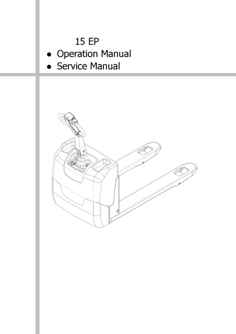
SERVICE MANUAL
HYUNDAI
FORKLIFT
20D-7
25D-7
30D-7
33D-7
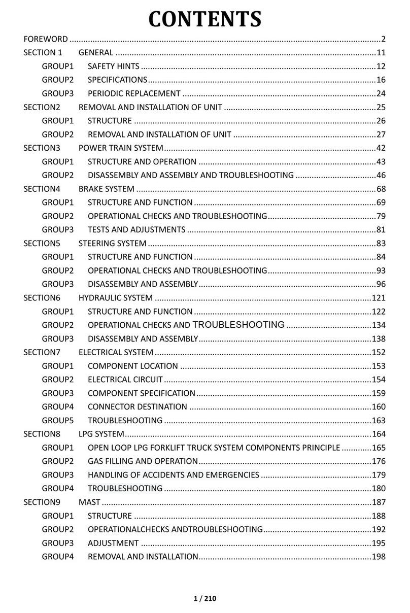
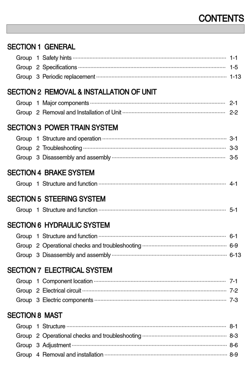
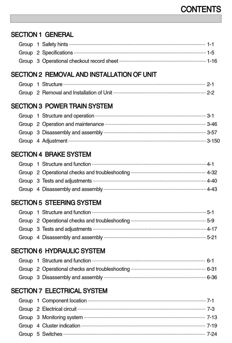
CONTENTS
SECTION 1 GENERAL
Group 1 Safety Hints
----------------------------------------------------------------------------------------------------
1-1
Group 2 Specifications
-------------------------------------------------------------------------------------------------
1-5
Group 3 Periodic Replacement
------------------------------------------------------------------------------------
1-13
SECTION 2 REMOVAL AND INSTALLATION OF UNIT
Group 1 Structure
---------------------------------------------------------------------------------------------------------
2-1
Group 2 Removal and Installation of Unit
--------------------------------------------------------------------
2-2
SECTION 3 POWER TRAIN SYSTEM
<OLD Transmission and drive axle>
Group 1 Structure and Operation
---------------------------------------------------------------------------------
3-1
Group 2 Troubleshooting
----------------------------------------------------------------------------------------------
3-21
Group 3 Disassembly and Assembly
---------------------------------------------------------------------------
3-25
<NEW Transmission and drive axle>
Group 1 Structure and Operation
--------------------------------------------------------------------------------
3-76
Group 2 Troubleshooting
----------------------------------------------------------------------------------------------
3-94
Group 3 Disassembly and Assembly
---------------------------------------------------------------------------
3-100
SECTION 4 BRAKE SYSTEM
Group 1 Structure and Function
-----------------------------------------------------------------------------------
4-1
Group 2 Operational Checks and Troubleshooting
------------------------------------------------------
4-8
Group 3 Tests and Adjustments
-----------------------------------------------------------------------------------
4-10
SECTION 5 STEERING SYSTEM
Group 1 Structure and Function
-----------------------------------------------------------------------------------
5-1
Group 2 Operational Checks and Troubleshooting
------------------------------------------------------
5-10
Group 3 Disassembly and Assembly
---------------------------------------------------------------------------
5-12
SECTION 6 HYDRAULIC SYSTEM
Group 1 Structure and Function
-----------------------------------------------------------------------------------
6-1
Group 2 Operational Checks and Troubleshooting
------------------------------------------------------
6-18
Group 3 Disassembly and Assembly
---------------------------------------------------------------------------
6-22
SECTION 7 ELECTRICAL SYSTEM
Group 1 Component Location
--------------------------------------------------------------------------------------
7-1
Group 2 Electrical Circuit
----------------------------------------------------------------------------------------------
7-2
Group 3 Component Specification
-------------------------------------------------------------------------------
7-10
Group 4 Connector Destination
-----------------------------------------------------------------------------------
7-11
Group 5 Troubleshooting
----------------------------------------------------------------------------------------------
7-13
SECTION 8 MAST
Group 1 Structure
---------------------------------------------------------------------------------------------------------
8-1
Group 2 Operational Checks and Troubleshooting
------------------------------------------------------
8-5
Group 3 Adjustment
-----------------------------------------------------------------------------------------------------
8-8
Group 4 Removal and Installation
--------------------------------------------------------------------------------
8-11
0-1
FOREWORD
1. STRUCTURE
This service manual has been prepared as an aid to improve the quality of repairs by giving the
serviceman an accurate understanding of the product and by showing him the correct way to perform
repairs and make judgements. Make sure you understand the contents of this manual and use it to
full effect at every opportunity.
This service manual mainly contains the necessary technical information for operations performed in
a service workshop.
For ease of understanding, the manual is divided into the following sections.
SECTION 1 GENERAL
This section gives the general information of the machine and explains the safety hints for
maintenance.
SECTION 2 REMOVAL & INSTALLATION OF UNIT
This section explains the procedures and techniques of removal and installation of each component.
SECTION 3 POWER TRAIN SYSTEM
This section explains the structure of the transmission as well as control valve and drive axle.
SECTION 4 BRAKE SYSTEM
This section explains the brake piping, each component and operation.
SECTION 5 STEERING SYSTEM
This section explains the structure of the steering unit, priority valve, trail axle as well as steering
circuit and operation.
SECTION 6 HYDRAULIC SYSTEM
This section explains the structure of the gear pump, main control valve as well as work equipment
circuit, each component and operation.
SECTION 7 ELECTRICAL SYSTEM
This section explains the electrical circuit and each component.
It serves not only to give an understanding electrical system, but also serves as reference material for
troubleshooting.
SECTION 8 MAST
This section explains the structure of mast, carriage, backrest and forks.
The specifications contained in this service manual are subject to change at any time and without any
advance notice. Contact your HYUNDAI distributor for the latest information.
0-2
Revised edition mark(
ΗΘΙÄ
)
When a manual is revised, an edition mark is
recorded on the bottom outside corner of the
pages.
R
Revisions
Revised pages are shown at the list of revised
pages on the between the contents page and
section 1 page.
Symbols
So that the shop manual can be of ample
practical use, important places for safety and
quality are marked with the following symbols.
2. HOW TO READ THE SERVICE MANUAL
Distribution and updating
Any additions, amendments or other changes will
be sent to HYUNDAI distributors.
Get the most up-to-date information before you
start any work.
Filing method
See the page number on the bottom of the
page.
File the pages in correct order.
Following examples shows how to read the
page number.
Example 1
2 - 3
Item number(2. Structure and
Function)
Consecutive page number for
each item.
Additional pages : Additional pages are
indicated by a hyphen(-) and number after the
page number. File as in the example.
1.
2.
3.
Symbol Item Remarks
Special safety precautions are
necessary when performing the
work.
Extra special safety precautions
are necessary when performing
the work because it is under
internal pressure.
Special technical precautions or
other precautions for preserving
standards are necessary when
performing the work.
Safety
Caution
ö
10 - 4
10 - 4 - 1
10 - 4 - 2
10 - 5
Added pages
SECTION 2 REMOVAL AND INSTALLATION OF UNIT
Group 1 Structure
---------------------------------------------------------------------------------------------------------
2-1
Group 2 Removal and Installation of Unit
--------------------------------------------------------------------
2-2
2-1
GROUP 1 STRUCTURE
SECTION 2 REMOVAL & INSTALLATION OF UNIT
1
2
3
4
5
6 7 8 9 10 1112 1314
15
16
17
18
1920
21
1 Mast
2 Lift cylinder
3 Tilt cylinder
4 Main control valve
5Fork
6 Front wheel
7 Drive axle
8 Transmission
9 Torque converter
10 Engine
11 Steering cylinder
12 Hydraulic pump
13 Steering axle (Rear)
14 Rear wheel
15 Muffler
16 Counterweight
17 Radiator
18 Seat
19 Overhead guard
20 Steering wheel
21 Air cleaner
20D7OM21
Forks
Lower the fork carriage until the forks are
approximately 25
mm
(1
in
) from the floor.
Turn knob up and slide one fork at a time
toward the center of the carriage where a
notch has been cut in the bottom plate for
easy removal.
Remove only one fork at a time.
On larger forks it may be necessary to
use a block of wood.
2-2
GROUP 2 REMOVAL AND INSTALLATION OF UNIT
1. MAST
REMOVAL
1)
(1)
Remove and install following units as explained in the flow chart.
Backrest
Knob
Carriage
Center notch
Fork
Pin
Spring
Backrest (If necessary)
Remove bolts securing backrest to fork
carriage. Lift backrest straight up and
remove it from carriage.
(2)
Backrest
Bolt
Carriage
20D7RE02
20D7RE03
Η
Θ
Ι
ö
Η
CCarriage
With the mast vertical, raise the carriage
high enough to place blocks under the
load forks. This is done to create slack in
the load chains when the carriage is
lowered. Lower the carriage all the way
down to the floor. Make sure the carriage
is level, this will prevent any binding when
the mast is raised.
(3)
20D7RE04
Η
2-3
While supporting lift chains, remove nuts
and split pin from the anchor bolt.
Θ
Outer mast
Lift chain
Nut
Split pin
20D7RE05
Pull the chains out of the sheaves and
drape them over the front of the carriage.
Ι
Carriage
Lift chain
Mast
Block
20D7RE06
Slowly raise inner mast upright until mast
clears top of fork carriage. Move carriage
to work area and lower the mast.
Make sure that carriage remains on
floor and does not bind while mast is
being raised.
Inspect all parts for wear or damage.
Replace all worn or damaged parts.
Κ
ö
Inner mast
Carriage
Lift chain
20D7RE07
3-63
Fasten RING BRG ADJUST.
Κ
20D7AXLE065
20D7AXLE066
20D7AXLE067
Paint marking(Both sides)
20D7PT35
Measure backlash again.
Bachlash of pinion shaft and ring gear is 0.15~0.2
mm
(0.006~0.008 in)
If backlash is wrong, carry out adjusting work.
Adjust the left / right of RING BRG ADJUST by one
and one clip.
Λ
ö
ö
Fit position.
Μ
Assemble cotter pin.
Ν
60%
40~75%
40~75%
60%
40%
40%
Heel
Toe Toe
Heel
Drive side(Forward) Coast side (Reverse)
20D7PT37
After assembling, adjust pattern of the gear and
pinion shaft as figure.
If pattern is not adjusted, take a measure as
measuring backlash again and then reassemble.
ö