manuals.online logo
Brands
  1. Home
  2. •
  3. Brands
  4. •
  5. IBM
  6. •
  7. Control Unit
  8. •
  9. IBM AR-B3001 User manual

IBM AR-B3001 User manual

Other IBM Control Unit manuals

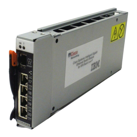
IBM BladeCenter Copper Pass-thru User manual
IBM

IBM BladeCenter Copper Pass-thru User manual

IBM BladeCenter Management Module User manual
IBM

IBM BladeCenter Management Module User manual

IBM 5294 Manual

IBM

IBM 5294 Manual

IBM Redbooks ServeRAID-MR10k User manual
IBM

IBM Redbooks ServeRAID-MR10k User manual

IBM Nways 8260 User manual

IBM

IBM Nways 8260 User manual
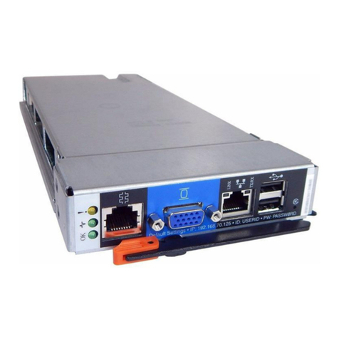
IBM BladeCenter Advanced Management Module User manual

IBM

IBM BladeCenter Advanced Management Module User manual

IBM BladeCenter 4-Port User manual

IBM

IBM BladeCenter 4-Port User manual

IBM WebSphere DataPower XI50B User manual
IBM

IBM WebSphere DataPower XI50B User manual

IBM 2702 Technical manual

IBM

IBM 2702 Technical manual

IBM 5394 User manual

IBM

IBM 5394 User manual

IBM 3270 User manual

IBM

IBM 3270 User manual

IBM 3274 51C Setup guide

IBM

IBM 3274 51C Setup guide

IBM 3274 User manual

IBM

IBM 3274 User manual

IBM MegaBasic IC697PCM711 User manual

IBM

IBM MegaBasic IC697PCM711 User manual
IBM Power System PCIe3 User manual

IBM

IBM Power System PCIe3 User manual
IBM 1620 Manual

IBM

IBM 1620 Manual

IBM 4769 User manual

IBM

IBM 4769 User manual

IBM 8271 Nways Ethernet LAN Switch User manual

IBM

IBM 8271 Nways Ethernet LAN Switch User manual

IBM 8250 User manual

IBM

IBM 8250 User manual

IBM color LaserJet 5500 Operating manual

IBM

IBM color LaserJet 5500 Operating manual

IBM 8260 User manual

IBM

IBM 8260 User manual

Popular Control Unit manuals by other brands

Seitz 14A80 user manual

Seitz

Seitz 14A80 user manual

Wilo RS485 Installation and operating instructions

Wilo

Wilo RS485 Installation and operating instructions

Becker CentralControl CC41 Commissioning Instruction

Becker

Becker CentralControl CC41 Commissioning Instruction

SICK CDB650 operating instructions

SICK

SICK CDB650 operating instructions

Panduit NetKey NKP5E88M Series installation instructions

Panduit

Panduit NetKey NKP5E88M Series installation instructions

MX Options Concentric Petite Fitting instructions

MX

MX Options Concentric Petite Fitting instructions

Clean Water Systems Fleck 2510 Installation & start?up guide

Clean Water Systems

Clean Water Systems Fleck 2510 Installation & start?up guide

Fairchild FSB44104A user guide

Fairchild

Fairchild FSB44104A user guide

LEGRAND Wattstopper LMIN-104 installation instructions

LEGRAND

LEGRAND Wattstopper LMIN-104 installation instructions

PMK ATT10BNCS instruction manual

PMK

PMK ATT10BNCS instruction manual

Tektronix TDS3FFT user manual

Tektronix

Tektronix TDS3FFT user manual

Woodward easYgen Technical manual

Woodward

Woodward easYgen Technical manual

Balluff BNI EIP-502-105-R015 user guide

Balluff

Balluff BNI EIP-502-105-R015 user guide

NXP Semiconductors TWR-LS1021A Getting started

NXP Semiconductors

NXP Semiconductors TWR-LS1021A Getting started

Advantech PCM-3117 Startup manual

Advantech

Advantech PCM-3117 Startup manual

Danfoss MCO 101 manual

Danfoss

Danfoss MCO 101 manual

Moons' Lin Engineering R701P user manual

Moons'

Moons' Lin Engineering R701P user manual

Aventics RV1 operating instructions

Aventics

Aventics RV1 operating instructions

manuals.online logo
manuals.online logoBrands
  • About & Mission
  • Contact us
  • Privacy Policy
  • Terms and Conditions

Copyright 2025 Manuals.Online. All Rights Reserved.

ACROSSER TECHNOLOGY 1
CHAPTER 1 INTRODUCTION
1.1 GENERAL DESCRIPTION
The AR-B3001 is a low cost, high accuracy, low noise,
low drift A/D interface boards for the IBM PC/XT/AT and
their compatibles. It is half-length boards that install
internally in an expansion slot of an IBM Personal
Computer to turn the computer into an inexpensive, high-
precisioninstrumentfortemperature,humidity,pressure,
flow and level etc.. The AR-B3001 is constructed with a
12-bit (plus polarity bit) dual-slop integrating A/D
converter. It can be operated with 16 single-ended or 8
differential analog inputs. The analog input range of AR-
B3001 is -5V to +5V.
A complete software utility containing demo programs,
Assembly, Basica, and C drivers are furnished with the
board to minimize user's effort on application software
development. All the driver routines are provided with
source programs and can be modified to suit your
applications.
Block diagram of AR-B3001 is shown in figure 1-1.
ACROSSER TECHNOLOGY
2
Figure 1-1 AR-B3001 Functional Block Diagram
1.2 FEATURES
Inexpensive, half-size analog input board for IBM
PC/XT/AT and their compatibles.
16 single-ended or 8 differential inputs.
Maximum throughput 30 Hz.
Resolution : 12-bit and a sign bit.
+5V to -5V input range.
Assembly, C, and Basica drivers included.
Easy to use.
ACROSSER TECHNOLOGY 3
1.3 ORDERING INFORMATION
Followings list and describe part number of the AR-
B3001 board and its accessories.
Part Number Description
AR-B3001 16 channel analog input card
with user’s manual
AR-B9006 34-pin screw terminal board for
AR-B3001 with 0.6m flat cable
ACROSSER TECHNOLOGY
4
This page is intentionally left blank
ACROSSER TECHNOLOGY 5
CHAPTER 2 INSTALLATION
This chapter provides instructions for installing the AR-
B3001 in an IBM PC/XT/AT and compatibles.
2.1 SWITCHE, JUMPER AND CONNECTOR
There is one DIP switch and one jumper on the AR-
B3001. This section describes functional use of the
switch and jumper. It also provides a description of the
input connector. Figure 2-1 shows the location of each
switch, jumper, and connector for AR-B3001. Table 2-1
list the functions of jumper, switch, variable resistors and
connector shown in Figure 2-1.
Legend Description
DIP SW I/O Port Base Address
JP1 Differential/Single-Ended Selection
JP7 Reserved
VR1 Fine Adjustment of Full-Scale
VR2 Rugged Adjustment of Full-Scale
VR3 Reserved
VR4 Offset Adjustment
VR5 Common Mode Rejection Ratio Adjustment
J2 Input Connector
Table 2-1
ACROSSER TECHNOLOGY
6
Figure 2-1 Board Layout of AR-B3001
ACROSSER TECHNOLOGY 7
2.1.1 Base Address Settings
There is one DIP switch located on the AR-B3001 card.
It is used to select the base port address of the AR-
B3001. The operation of AR-B3001 is controlled through
the I/O ports. Four consecutive I/O ports are used by AR-
B3001. The base address of these I/O ports is selected
by using base address switch DIP SW. The AR-B3001 is
factory-configured for a base address of 3e0 Hex. If this
base address is already occupied, you will need to
change the base address switch setting. It is essential
that each peripheral device, such as an AR-B3001, be
assigned a unique base address within the range of 200
to 3fc Hex and that the address is on a 4-byte boundary.
Figure 2-2 shows the base address switch.
ON
12345678
DIP SW
A2 A3 A4 A5 A6 A7 A8 A9
Figure 2-2. Base Address Switch
ACROSSER TECHNOLOGY
8
Use the following table to select an AR-B3001 base port
address.
DIP SW ADDRESS ADDRESS VALUE
LINE Hex. Dec.
Switch 1 A2 4 4
Switch 2 A3 8 8
Switch 3 A4 10 16
Switch 4 A5 20 32
Switch 5 A6 40 64
Switch 6 A7 80 128
Switch 7 A8 100 256
Switch 8 A9 200 512
Address = 200*A9 + 100*A8 + 80*A7 + 40*A6 + 20*A5
+ 10*A4 + 8*A3 + 4*A2 (Hex)
-or-
Address = 512*A9 + 256*A8 + 128*A7 + 64*A6 + 32*A5
+ 16*A4 + 8*A3 + 4*A2 (Dec)
A9....A2 = 0 If switch is ON.
A9....A2 = 1 If switch is OFF.
Note: Setting the switch to the "ON" position indicates a
logical "0" and setting the switch to the "OFF"
position indicates a logical "1".
ACROSSER TECHNOLOGY 9
Use the following table as an aid for selecting an
unoccupied address.
HEX RANGE DEVICE
00-FF Reserved For System
170-178 Fixed Disk 1
1F0-1F8 Fixed Disk 0
201 Game Port
208-20A EMS Register 0
218-21A EMS Register 1
278-27F Parallel Printer Port 3 (LTP3)
2E8-2EF Serial Port 4 (COM4)
2F8-2FF Serial Port 2 (COM2)
300-31F Prototype Card/Streaming Type Adapter
378-37F Parallel Printer Port 2 (LTP 2)
380-38F SDLC, Bisynchronous 2
3A0-3AF Bisynchronous 1
3B0-3BF Monochrome Display and Parallel Printer
Port 1 (LPT1)
3C0-3CF EGA/VGA Adapter
3D0-3DF Color/Graphics Monitor Adapter
3E8-3EF Serial Port 3 (COM3)
3F0-3F7 Diskette Controller
3F8 3FF
S i l P t 1 (COM1)
Table 2-2. IBM PC I/O Address Map
ACROSSER TECHNOLOGY
10
2.1.2 Channel Configuration Jumper
The JP1 is used to select whether 16 single-ended or 8
differential analog input channels are to be used. To
select eight differential input channels, move the jumpers
to the right side. Likewise, to select 16 single-ended
analog input channels, move the jumpers to the left side
as shows in Figure 2-3.
JP1
Differential
JP1
1
Single-ended
(Factory preset)
1
Figure 2-3 Channel Configuration Jumper