3
Programmable Coprocessor Module GFK-0164G
Coprocessor Modules
August 1997
Programming and Configuration
AnIC647 or IC640 computer, or IBM-compatible PC,
XT, or AT computer with PCM Development Software
installed is connected to the top port of the PCM. The
default setting is 19,200 bps. The PCM Development
Software is used to configure the serial port parame-
ters, to define the interface to the PLC CPU, to select
task functions and to program MegaBasic applica-
tions. The PCM parameters can also be configured
using MS-DOS
r
or Windows
r
programming soft-
ware. Consult reference 3 for details of operation.
2
3
4
5
8
20
7
TXD
RXD
RTS
CTS
GND
PIN
RXD
TXD
CTS
DTR
SHLD
GND
3
2
5
20
8
1
7
IC647 AND
IBM PS/2
25-PIN CONNECTOR
PCM
25-PIN
CONNECTOR
PIN
ÎÎ
ÎÎ
a43735
3PL
4PL
PCM
IC697CBL705
RS-232
(DEFAULT PORT)
PCM
PROGRAMMING S/W
Programmer
Figure 3. PCM Development System Connection to PCM
Serial Ports
Both ports are RS-232 and RS-422/RS-485 compatible.
Both ports acting simultaneously can each support up
to 9.6 Kbaud full duplex data communications, or they
can support up to 19.2 Kbaud individually.
Port 1 (3PL) and Port 2 (4PL)
Connectors 3PL and 4PL contain signals for both RS-232
and RS-422/RS-485 types of communication circuits. The
pin-out for the RS-232 signals are per the RS-232 specifi-
cation with an exception that pins not normally used for
RS-232 are used for RS-422/RS-485 signals. Details are
shown in tables 1 and 2.
Table 1. Port 1 or 2 - RS-232
PIN FUNCTION SIGNAL
NAME I/O
1Shield - -
2TransmittedData TD Output
3ReceivedData RD Input
4RequestTo Send RTS Output
5ClearTo Send CTS Input
7SignalGround 0V -
8DataCarrier Detect DCD Input
20 Data TerminalReady DTR Output
Table 2. Port 1 or 2 - RS-422/RS-485
PIN FUNCTION SIGNAL
NAME I/O
9SendData (A) SD(A) Output
10 Request to Send (A) RTS(A) Output
11 Clear to Send (A) CTS(A) Input
12 Termination for pin 13 - -
13 ReceiveData(A) RD(A) Input
21 Send Data (B) SD (B) Output
22 Request to Send (B) RST (B) Output
23 Clear to Send (B) CTS(B) Input
24 Termination for pin 23 - -
25 ReceiveData (B) RD (B) Input
Configuration
There are no user DIP switches or jumpers on this
board for configuration. However, the board must be
configured before operation using PCM Development
Software (See reference 3).
Status Indication
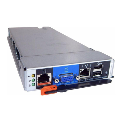
Three Status LEDs are available as shown in Figure 2.
The top LED indicates the condition of the module, the
bottom two LEDs may be assigned to a configured
function.
Controls
One pushbutton is provided. Push and hold for less
than 5 seconds will restart an application. Push and
hold for more than 5 seconds and the module factory
default configuration will be installed (this action will
not clear memory but will permit communication with
the programmer using factory default settings).
