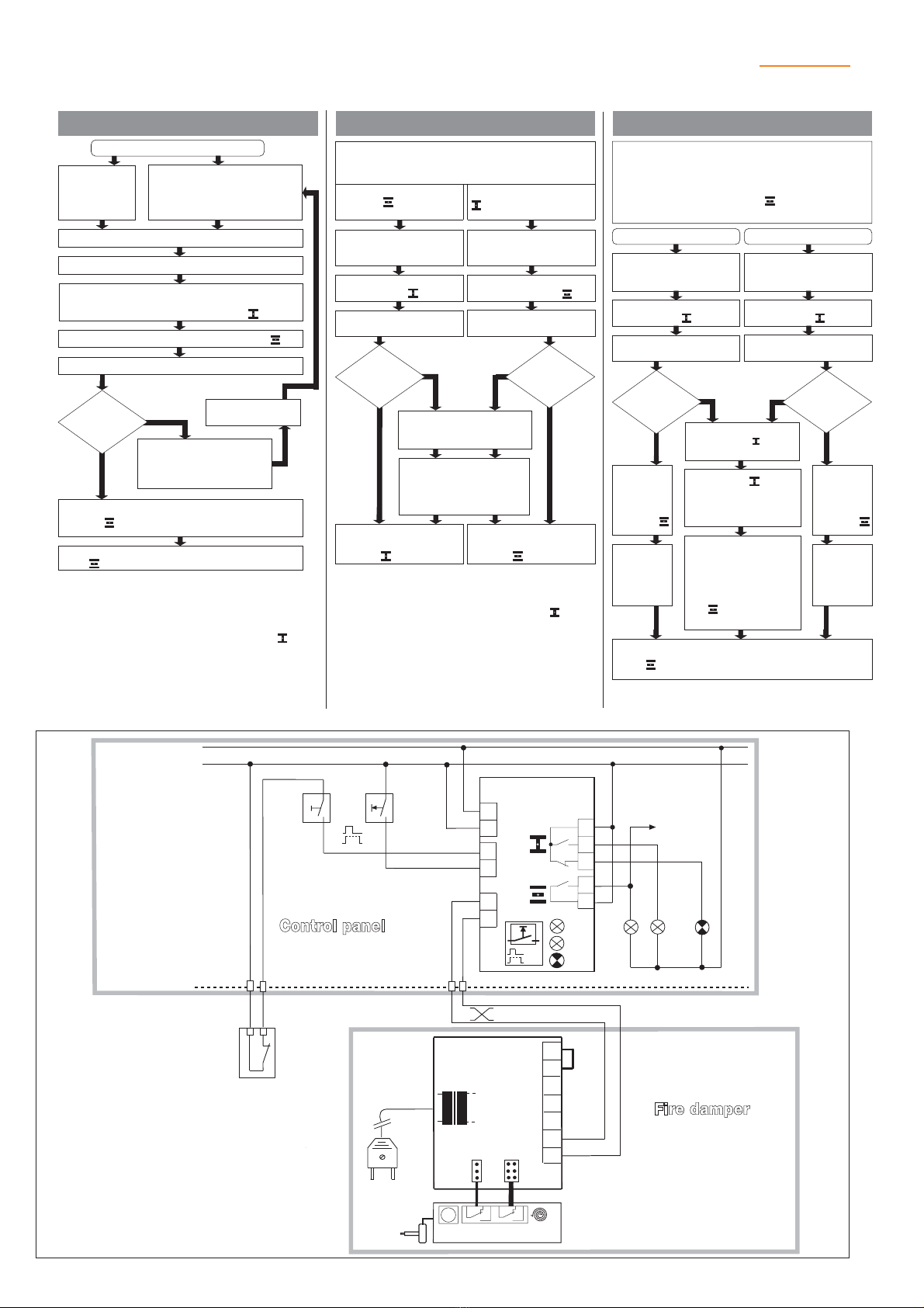
General notes
•The test will be interrupted if a fault occurs during the
test run. The LED “Alarm” flashes to signal a new
fault. The two LED’s “Open” and “Close” are dark
and the damper moves to the safe position .
Contact 6–3 (fault) is closed in this case.
•Anew test run can be started by pressing “Reset/Test”,
by issuing a reset command via terminal 5 or by
interrupting the AC 24 V power supply.
Triggering by:
Energising
of AC 24 V
power supply
Press “Reset/Test” when a new
fault occures ( LED “Alarm”
flashing) or when a fault is stored
(LED “Alarm” steady)
Start – Test sequence
A short unlocking pulse triggers the actuator au-
tomatically if it has been locked manually. So the
damper is moved to the safe position
All LEDs (Open, Close and Alarm) steady
Actuator moving to the operating position
Contact 6–3 (fault) remains closed
When the damper has reached the operating po-
sition , LED “Open” goes steady
All LEDs (Open, Close and Alarm) steady
LED “Alarm” flashes after
a delay and contact 6–3
(fault) is closed
Rectify fault in
system
Damper moves further towards the operating
position . LED “Open” flashes during motion
NO
YES
Actuator
reached switching
position
10°
LED “Close” steady,
i.e. damper in safe
position
LED “Open” steady,
i.e. damper in operating
position
Precondition:
No new faults!
(LED “Alarm” must not be flashing)
Damper in operating
position , LED “Open”
steady
Damper in safe position
, LED “Close” steady
Normal operation
Plant switch
(see Circuit diagram)
at “Control OFF”
Plant switch
(see Circuit diagram)
at “Control ON”
Damper moves to
operating position
Damper moves to
safe position
LED “Close” flashes
during the motion
LED “Open” flashes
during the motion
NO
LED “Alarm” flashes, i.e. a new
fault has occured (contact 6-3
closed)
If the end position is reached
later, LED
“Alarm” changes to
steady and contact 6–3 opens
YES
NO
YES
Actuator
reached switch-
ing position > 80º
within 320 s
Actuator
reached switch-
ing position < 10º
within 35 s
General notes
• If a fault in the system is detected during operation
the damper will move to the safe position imme-
diately. LED “Alarm” starts to flash in order to signal
a new fault and contact 6–3 is closed.
•When the fault has been rectified, the system can be
restarted by pressing “Reset/Test”, by injecting a
reset command via terminal 5 or by interrupting the
AC 24 V power supply.
• No new faults ( LED “Alarm” flashing) and no
stored faults (LED “Alarm” steady)
• Damper in operating position , i.e. LED “Open”
steady
Preconditions:
LED “Close” flashes
during the motion
Local activation
Periodic damper function test
External activation
Press and hold
“Reset/Test”
Activate Reset/Test com-
mand via terminal 5
Damper moves to
safe position
Damper moves to
safe position
LED “Close” flashes
during the motion
NO
Damper continues moving
to safe position and LED
“Close” continues flashing
Safe position reached
after ca. 20 s (spring-
return time) and LED
“Close” steady
YES
NO
YES
“Reset/Test”
command to ter-
minal 5 remains
activated
“Reset/Test”
remains
depressed
If “Reset/Test” is relea-
sed or the Reset/Test
command via terminal
5 is deactivated, the
damper will move back
to the operating posi-
tion
(LED “Open” flashes)
LED“Open”
flashes
during the
motion
Damper
moves
back to
operating
position
LED ”Open” steady signals damper in operating po-
sition
LED“Open”
flashes
during the
motion
Damper
moves
back to
operating
position
~
2
10
1
5
9
11
Reset
Test
AC
24 V
BKS24-1B
6
4
3
7
8
T
AC 24 V
Control
ON / OFF
Open Close Fault
eventual
fan enabling
Contact
from fire
alarm
system
Connections interchangeable
Open
Close
Alarm
Reset
Test
BKN230-24
Power supply
AC 230 V
1
2
3
4
5
6
7
a
b
BF(G)24-T-ST, BF..24-ST
M
BAE72-S
ENG-93001-93334-08.03-PDF • Subject to technical changes
Functional sequences / Typical wiring diagram
w0624810
BC


