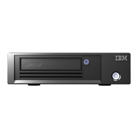
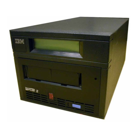
IBM 9348 Operating and installation instructions

9348
Service Information

Beforeusingthis informationand the product itsupports,besure to readthe general informationunder "Notices"
on
iii.
Third Edition(January
1992)
Makesureyou are usingthe proper edition for the levelof the product.
Order publicationsthroughyour IBM representativeor the IBMbranchserving your locality. Publications are not
stockedat the address givenbelow.
A form for readers' commentsisprovidedatthe back of this publication. Ifthe form has been removed, address your
commentsto:
Attn Department
245
IBMCorporation
3605 Highway52 N
Rochester, MN 55901-7899 USA
When you send informationto IBM, you grant IBMa non-exclusiveright
to
useor distributethe informationinany
O
CopyrightInternationalBusinessMachinesCorporation
1989,1992.
All rightsresewed.
Noteto U.S. Government Users
-
Documentationrelatedto restrictedrights
-
Use, duplicationor disclosure is
subject to restrictionsset forth inGSA ADP Schedule Contractwith IBMCorp.

Notices
--
Safety Notices in
This
Manual
Danger Notices
A
danger notice indicates a hazardthat could possibly cause deathor serious per-
sonal injury.
The following danger notices pertain throughoutthis manual.
DANGER
An electricaloutletthat isnotcorrectlywired couldplacehazardousvoltage
on metal
parts
of the systemor the productsthat attachtothe system.
It
is
the customer's responsibilityto ensurethatthe outletiscorrectlywiredand
groundedtopreventanelectricalshock.
1.
To preventa possibleelectrical shock when installingthe device, ensure
thatthe powercordfor that device isunpluggedbefore installingsignal
cables.
2.
To preventa possibleelectrical shock when addingthe devicetoa
system, disconnectallpower cords, ifpossible, fromthe existingsystem
beforeconnectingthe signalcable tothatdevice.
DANGER
To prevent
a
possibleelectricalshockfromtouchingtwosurfaces with dif-
ferentelectricalgrounds, useone hand, when possible,
to
connedor dis-
connectsignalcables.
(RSFTDOW)
DANGER
To preventa possibleelectricalshock duringanelectrical storm, do not
connector disconnectcablesor station protectorsfor communications lines,
displaystations, printers,ortelephones.
(RSFTDCW)
DANGER
To prevent an automaticpowerlonduringservice procedures, setthe
keylockswitchonthe systemunitcontrolpanelto the Manualor Secure
position.
DANGER
Ensurethatyoucompletethe followingstep. An electricaloutletthatisnot
corredly wired couldplace hazardous voltage onthe metal
parts
of the
sgstemor the p-e systiem.
(RSFTDOIB)
Q
Copyright
IBM
corp.
1989,1992
iii

Caution Notices
A
caution notice indicates a hazardthat could possibly cause minor personal injury.
Warning Notices
Warning
indicates a hazardthat could possibly
cause
damageto
a
program,
device,
system,or data.
Special Notices References inthis publication to IBMproducts, programs, or services do not imply
that IBMintendstomake these available inall countries inwhich IBMoperates.
Any referenceto an IBM licensed program or other IBMproduct inthis publication
is not intendedtostate or implythat only IBM's programorother productmay be
used.
IBMmay have patentsor pending patentapplications covering subject matter inthis
document. The furnishing ofthis document does not give you any license tothese
patents. You can send license inquiries, inwriting, tothe IBMDirector of Commer-
cial Relations, IBMCorporation, Purchase,
NY
10577.
The following terms, denotedby an asterisk
(')
inthis publication, aretrademarks of
the IBMCorporation inthe UnitedStates and/or other countries:
IBM
The followingterms, denoted by a double asterisk
(**)
inthis publication, aretrade-
marksofother companies as follows:
TORX Textron Inc.
This pub1icationcould containtechnical inaccuraciesor typographical errors.
The drawings and specifications contained herein shall not be reproduced inwhole
or inpart without the written permission of IBM.
IBMhas prepared this maintenance manualfor use by hardwareservice represen-
tatives inthe maintenanceor repairof the specific machines indicated. IBMmakes
norepresentationsthat it issuitable for any other purpose.
/V
9348
Service
Information

About
This
Manual
Who Should
Use This
Manual
This manual may referto productsthat are announced, but not currently available,
orto products that had not been announced when this manual was printed. IBM
makes no commitment toprovide any unannounced products referred to herein.
The final decision toannounceany product is basedon IBM's business and tech-
nicaljudgment.
Service representatives should usethe procedures and information inthis manual
torepairthe
9348
tape unit.
This manual uses a specific range of words sothat the text can be understood by
service representatives incountries where English isnot the indigenous language.
It is assumedthat the service representative using this manual has a basic under-
standing ofthe
9348
tape unit.
How
This
Manual
Is
Arranged
This manual contains:
Listsofsafety notices that appear inthis manual
A table of contents showing allthe procedures inthis manual and the pageon
which each procedure starts
Chapterscontaining:
-
Analyzing Problems
-
Part Locations
-
Service procedures
-
Cleaning
-
Safety Inspection Guide
-
Parts Catalog
-
Part Number Index
Appendixes containing diagnostic information
-
A Control PanelOperations
-
6
DiagnosticTests
Note:
Appendix
B
contains reference information and isto be used by
second-leve1 support personnel.
-
C
Logs
-
DConfigurations
A Glossaryofterms.
An index of key words used inthis manual
O
Copyright
IBM
Corp.
1989,1992

--
-
-
-
Related Printed Information
See the
9348
manual
CustomerInformation,
SA21-9567,
for informationon operating
the tape unit.
~i
9348
Service Information

Contents
Notices
..................................................
iii
...................................
Safety Notices inThis Manual
iii
...........................................
Danger Notices
iii
..........................................
Caution Notices iv
..........................................
Warning Notices iv
............................................
Special Notices iv
AboutThisManual
..........................................
v
...................................
Who Should UseThis Manual v
...................................
HowThis Manual IsArranged v
....................................
Related Printed Information vi
................................
Chapter
I
.
Analyzing Problems
1-1
Startingthe Service Call
.....................................
1-1
..........................................
ReferenceCodes
1-2
.......................................
Test Parameters
1-2
...................................
Intermittent Problems
1-2
ReferenceCode Tables
....................................
1-3
............................................
StatusCodes
1-32
NoResponseService Check
..................................
1-35
.
....................................
Chapter
2
PartLocations
2-1
...............................................
Locations
2-1
...........................................
Control Panel
2-1
.................................................
Front
2-2
..................................................
Top
2-3
...............................................
Bottom
2-4
.................................................
Rear
2-5
...........................................
Table-top Unit
2-6
.
Chapter
3
Service Procedures
.................................
3-1
Introduction
..............................................
3-1
Placingthe
9348
inthe Service Position
...........................
3-1
Placingthe
9348
inthe Operating Position
.........................
3-9
Cardand Battery Removal
...................................
3-15
Cardand Battery Installation
.................................
3-20
Connector BoardRemoval and Installation
........................
3-26
Program Module Removaland Installation
........................
3-29
Front PanelAssembly Removal
...............................
3-30
Front PanelAssembly Installation
..............................
3-35
Motor/Power Card Removal
..................................
3-42
MotorIPowerCard
l
nstallation
................................
3-45
Sensors and Sensor Card Removal
.............................
3-48
Sensors and Sensor CardInstallation
...........................
3-50
Speed Encoder Removal
....................................
3-52
...................................
Speed Encoder Installation
3-54
Tape Lifter Removal
.......................................
3-56
......................................
Tape Lifter Installation
3-57
Tension Arm and BOT/EOT Sensor Removal
.......................
3-59
Tension Arm and BOTIEOTSensor Installation
.....................
3-63
Head PlateAssemblv Removal
................................
3-67
Head PlateAssembly
l
nstallation
..............................
3-73
(O
Copyright
IBM
Corp
.
1989.
1992
vii

...................................
Motors and Hubs Removal 3-78
.................................
Motors and Hubs Installation 3-85
.....................................
Blower Motor Removal 3-90
....................................
Blower Motor Installation 3-94
Hub LockSolenoid and Hub Release Lever Removal
.................
3-97
Hub LockSolenoid and Hub Release Lever Installation
................
3-99
....................................
InterfaceCard Removal 3-101
..................................
InterfaceCard Installation 3-106
...............................
Fuse Removal and Installation 3-110
.....................................
Cooling Fan Removal 3-114
....................................
Cooling Fan Installation 3-116
.................................
AC-PowerModule Removal 3-119
.................................
AC Power Module Installation 3-120
............................
Table Top Unit Enclosure Removal 3-123
EnclosureInstallation
.....................................
3-128
........................................
.
Chapter
4
Cleaning 4-1
Cleaning Recommendations
...................................
4-1
..........................................
Cleaning Supplies 4-1
........................................
Cleaning Procedure 4-3
Chapter
5
.
Safety InspectionGuide
..............................
5-1
Getting Ready
............................................
5-1
SafetyConditions
........................................
5-1
SafetyEducation
.........................................
5-1
Chemicals
.............................................
5-1
Performing the Inspection
..................................
5-2
ReferenceInformation
.....................................
5-2
Covers
.................................................
5-2
Fuse
...................................................
5-2
Slide Stopping Screws
.......................................
5-3
Pivot Locking Screws
.......................................
5-5
.............................................
Safety Labels 5-7
Safety Grounds
...........................................
5-8
Power Cable
.............................................
5-9
Chapter
6
.
PartsCatalog
.....................................
6-1
HowTo Use This Parts List
....................................
6-2
Assemblies
..............................................
6-3
Assembly 1: Labelsand Slides
...............................
6-4
Assembly 2: Final Assembly
................................
6-8
Assembly 3: Front Cover Assembly
...........................
6-14
Assembly 4: Table Top Assembly
............................
6-16
Assembly 5: Table-Top Assembly Cables
.......................
6-18
Assembly 6: LineCord Chart for Table Top Units
..................
6-20
Chapter
7
.
Part Number Index
.................................
7-1
Appendix A
.
Control PanelOperations
...........................
A-1
Description
..............................................
A-1
Operator Buttons
.......................................
A-2
Service Representative Buttons
.............................
A-2
Lights
..............................................
A-2
DiagnosticMode
...........................................
A-3
INFO Option
.............................................
A-4
~iii
9348
Service
Information
.....................................
.......
TEST'Option
:
A-4
............................................
CONF
*
Option A-4
................................................
ID
*
Option A-5
.....................................
Running Diagnostic Tests A-5
.................................
.
Appendix
B
DiagnosticTests
B-I
.........................................
Power-On Self-Test B-1
...........................................
SequenceTests B-I
................................
DiagnosticTest 0 (Power On) B-I
.....................................
User-Defined Sequences B-6
.............................................
KernelTests 8-7
........................
Processor Communication Tests
(50
.
59)
B-8
...........................................
Loop-BackTests B-9
......................................
Controller CardTests 6-11
.......................
DiagnosticTest 70 (Control Panel Lights) B-I
I
........................
Diagnostic Test 71 (Front Panel Buttons) B-I
I
.........................................
Buffer Card Tests B-16
.......................................
InterfaceCardTests B-16
..................................
Tape Unit Operational'Tests B-16
AppendixC
.
Logs
........................................
C-1
......................................
Display and Clear Logs C-I
.............................................
Clear Logs C-I
...........................................
Display Logs C-I
.................................
Error Log Information(INFO 0) C-I
.....................................
Viewing the Error Log C-I
.....................................
Clearing the Error Log C-2
...................................
2
.
Present Error Rate C-2
...................................
3&4-TotalErrorData C-3
.....................................
5
.
Total Error Rate C-3
.................................
10
.
Tape Movement Log C-4
.....................................
12-Tape Unit Clock C-4
......................................
13
.
PowerCycles C-4
.......................................
15
.
Battery Date C-4
...........................
20
.
Drive Repositioning Statistics C-4
...........................
21
.
Tape Automatic loadStatistics C-5
...................................
24
.
Unit Type Number C-5
.....................
25
.
Program Module Kit Revision Number C-5
..................................
26
.
Unit Serial Number C-5
...................................
Appendix
D
.
Configurations
D-I
.................................
Changing ConfigurationValues D-1
...........................
Changing LockedConfiguration Values D-I
..................................
Changing ID(Address) Value D-2
................................................
Glossary
G-I
Index
..................................................
X-1
Contents
ix

X
9348
Service
Information

Figures
1.1
.
1.2 .
1.3 .
1.4 .
1.5 .
1.6 .
1.7
.
1.8 .
1.9
.
1.10 .
1.11
.
1.12
.
1.13 .
1.14 .
1.15
.
A-I
.
Command RejectReferenceCodes ........................1-3
Tape Read ReferenceCodes
............................
1-6
Tape Write ReferenceCodes
............................
1-9
Tape Positioning/ServoReferenceCodes
...................
1-14
Tape Unit Controller ReferenceCodes ..................... 1-18
BufferController ReferenceCodes
.......................
1-19
InterfaceController ReferenceCodes
.....................
1-20
3xx Tape Unit Controller DiagnosticReference Codes
..........
1-22
04xx Buffer Controller ReferenceCodes
....................
1-25
06xx InterfaceController ReferenceCodes .................. 1-27
OCxx Multiprocessor and OExx Microcode ReferenceCodes
......
1-28
ReferenceCodes Generated
By
The Host System
.............
1-29
PartNumberTable
..................................
1-30
StatusCodes
......................................
1-32
Status Codes ...................................... 1-34
DiagnosticTest Conditions
.............................
A-6
@
Copyright
IBM
Corp
.
1989.
1992

~ii
9348
Service Information
Chapter
1.
Analyzing
Problems
Starting
the
Service
Call
Ifyou havea reference code, goto "ReferenceCodes" on page 1-2.
Ifyou do not havea reference code, butyou have a status code from the 9348
control panel,goto "Status Codes" on page 1-32.
Ifyou do not havea reference codeora status code, gotothe system console and
usethe proceduresthe system hasfor analyzingthe problem. For example, look in
the system error logtodetermine the referencecode. Then go to "Reference
Codes" on page 1-2.
Ifyou do not havea reference code becausethe tape unit cannot generate a refer-
ence code, power off thistape unit,then power iton again.
1
If
***
xx orF999 occurs, goto "Status Codes" on page 1-32.
Ifthetape unit does not respond,goto "No Response Service Check" on page 1-35.
Ifyou have a reference code that is not in "ReferenceCodes" on page 1-2, goto
reference code FFD7on page 1-29.
Ifthe operator orthe system report excessivewrite or read errors, goto reference
code0022 on page 1-6.
Ifthe front panel access door will not open, go tothe "Front PanelAssembly
Removal" on page 3-30 and "Front Panel Assembly Installation" on page 3-35 pro-
cedures and exchange the door solenoid.
Ifboth density lights (1600 and6250) are offorifbothdensity lights are on when the
tape is loaded, then thetape is blank,written at some other density, or has a
damaged ID burst. Exchangethetape with a goodtape.
Ifthe File Protectedlight isalways on when atape isloaded with the write enable
ring inplace, orthe File Protectedlight will not come onwhen atape is loadedwith
the ring removed,goto reference code 0070 on 1-15.
@
Copyright
IBM
Corp.
1989,lS92
1-1

Reference
Codes
When the customer reports a 9348 unit reference code:
1. Findthe reference code inone of the reference codetables onthe following
pages.
2. Perform each action described inthe Action column, inthe sequenceshown,
untilthe problem iscorrected.
The FRUs with the highest percent of probable cause should be exchangedfirst
unless you are instructed tododifferently. Ifexchanging a FRUwiththe highest
percent of probablecause does not correct the problem,then installthe original
item and exchangethe failing item with the next highest percent ofprobable cause.
Continueto exchange and install the FRUs, one at atime, untilthe problem iscor-
rected.
The connector card, part number 21F7924, should be checked visually for bent pins
orother damage when a read/write card, controller card, orbuffer card islisted as a
FRU. The connector card isnot always listed as a FRU.
Sometimes a low percent FRU will betestedfirst because it is easier toisolate
it
from the other FRUs.
lnformationon howto runthetests listed inthe referencecodetables islocated in
"Running Diagnostic Tests" on page A-5.
Test Parameters
Sometests inthe Action column need a test parametertobekeyed inbefore
runningthe test. For example, test
98
needs parameterA to be 6250 or1600.
Ifthe parameter is not specified inthe Action columnfor a test that needsa param-
eter, usethe parameterthat appears inthe status display (default).
IntermittentProblems
Ifa problem is intermittent and all thetests inthe Action column run correctly, use
the FRU percent todeterminethe sequencefor exchanging FRUs.
1-2
9348
Service
lnformation

Reference Code Tables
Figure
1-
I
(Page
1
of
3).
CommandReject Reference Codes
Ref'
/
PartNumber
Code
0001 90%
1
No tape isloaded. Loada tape and attemptthe operationagain.
Probable
Cause
Tape
21F7930
0002
Action
Operator
21F7917
Ifthe referencecode continuesto occur,exchangethe FRU. Verify the
repair by writing to tape from the system.
9%
90
'10
9%
-
-
-
-
-
-
-
-
-
-
Ifthere isno write-enableringon the tape, installone. Then attempt
the operation again.
Ifthe referencecode continuestooccur, exchangethe FRU. Run test
2to verify the repair.
You haveattemptedto get accessto the tape unitfrom the system
whilethe tape unitwas not online. Pressthe Online button to putthe
tape unitonline. Then attemptthe operationagain.
Ifthe referencecodecontinuesto occur,exchangethe FRU. Run test
2to verify the repair.
A tape isloadedand preventingthe diagnosticfrom beingrun.
Removethe tape and runtest 76.
0005
Ifthe referencecode continues to occur, exchangethe FRU. Run test
76
to
verifythe repair. Ifthe referencecode continues
to
occur,
contactyour nextlevel of support.
Lic int
code
21F7930
--
-
Operator
21F7919
21F7930
-
-
-
--
-
-
--
-
-
-
-
Ifthe front door or the topcover isopen, close it. Then attemptthe
operationagain.
Ifthis referencecode continuesto occur, runtest
88.
The status
display will beblankifthe doors areclosedcorrectly. The word
DOOR will appear inthe display ifeither the door or the top cover is
opened. If DOOR appears inthe displaywhen the door and top cover
areclosed, exchange the FRUs as needed, and runtest
88
after each
FRU isexchanged to verify the repair.
OOOA Tape
21F7923
21F7933
The tape unitcannotreada tape that has not been initializedor isnot
writtenwith the correctdensity. The tape must be initializedat 1600 or
6250 bitsper inch. Also, the tape pathmay bedirty.
Cleanthe tape path; see "Cleaning Procedure" on page 4-3. Run test
150
and 177 to verifythe repair. Ifthis referencecode continues to
occur,exchange the readlwritecard and runtest 162 to verify the
repair.
-
OOOB
-
-
Operator
21F7923
21F7933
21F7930
-
-
--
-
-
-
The tape unitcannotwriteon the tape. Ensurethat the tape is at BOT
and attemptthe operation again.
Ifthis referencecode continuesto occur, exchangethe tape sensor
cardand attemptwriting fromthe system to verify the repair. Ifthe
referencecode continues to occur, exchangethe remainingtwo FRUs
as needed; and runtest 151 after each of these FRUs isexchanged
to
verify the repair.
000D
Chapter
1.
Analyzing Problems
1-3
21F7931
Lic int
code
95
'10
4% Thetape was already at BOT when a backspacecommandwas sent
from the system
to
the tape unit. This is notpermitted.
Ifthis didnotoccur, exchange the FRU and attempttheoperation
again. Ifthe referencecode continues to occur, contact your next
levelof support.

--
--
Figure
I-?
(Page
2
of
3).
Command Reject ReferenceCodes
Ref.
Code PartNumber Probable
Cause
OOOF
Action
Tape
ticint
code
The tape was 10 feet beyond EOT when a write command was
receivedfrom the system. The EOT marker may
be
too far from the
end of the tape. Verify that the EOT marker iscorrectlyplaced. See
referencecode 0060 for a method
to
find the EOT marker. The
9348
Customer Information
manualcontains more informationon looking
for an EOT marker.
Ifyou found thatthe EOT marker was not correctlyplaced, attemptthe
operationagainwith a new tape. Do not attach an EOT marker to the
customer's tape at this time. You may losedata if you attach an EOT
marker to the failing tape.
Ifthis referencecodecontinues tooccur, contactyour next level of
support.
The commandreceivedfrom the system by the tape unit was illegal.
Ask the operator to correctthe command and to attemptthe operation
again.
Ifthe commandwas correct and the referencecode continues
to
occur,exchange the FRUs as needed, and runtest
10
after each
exchangeto verify the repair.
Ifthis referencecode continues tooccur, contact your next levelof
support.
56F0080
21F8063
21F7926
ticint
code
56F0080
21F8063
21
F7926
Lic int
code
The commandreceivedfrom the system by the tape unitcontained an
illegalparameter. Ask the operator to correctthecommandand to
attemptthe operationagain.
Ifthe commandwas correctand the referencecode continuesto
occur, exchangethe FRUs as needed, and runtest
11
after each
exchangeto verify the repair.
Ifthis referencecode continuesto occur, contactyour next levelof
support.
21
F8063
tic int
code
The commandreceivedfrom the system by the tape unitcontained an
illegalTEST
*
or INFO number. Correctthe command and attempt
theoperationagain.
Ifthe commandwas correctand the referencecode continuesto
occur,exchange the FRU. Then attempt the operationagain to verify
therepair.
Ifthis referencecode continues to occur, contact your next level of
support.
21F8063
Lic int
code
The commandreceivedfrom the system by the tape unitattemptedto
runa test that is not remotely accessible. Ensurethat the test is
remotely accessible.
Ifthe test isremotelyaccessibleand the referencecode continues to
occur, exchange the FRU. Then attempt the operation again to verify
the repair.
Ifthis referencecode continues to occur, contact your next levelof
support.
Operator
21F8063
-
--
Cancel was pressedon the tape unitcontrol panelwhen atest was
beingrun. Attempt the test again.
needed. Attempt the test again after each FRU isexchanged to verify
the repair.
1-4
9348
ServiceInformation

tic int
I
code
Figure
1-1
(Page
3
of
3).
Command Reject Reference Codes
Operator
21F8063
tic int
code
Action
Test 38 was runwith more steps enteredthan are permitted. Enter the
correctnumber of steps and attemptthe test again.
Operator
21F8063
Probable
Cause
75%
20
O/O
Ref.
Code
0015
Part
Number
Operator
21F8063
4%
75
O/O
20
%
4%
ticint 2%
code
I
Ifthis referencecode continuesto occur, exchange the FRU. Ifthe ref-
erencecode continuesto occur, contactyour next levelof support.
The systemhas requesteda densitythat is not availableon the tape
unit. Select 1600 or 6250 bitsper inchand attemptthe operation
again.
95%
2
O/O
21F8063
21F7926
tic int
Ifthis referencecode continuesto occur, exchange the FRU and
attemptthe operationagainto verify the repair. Ifthe referencecode
continues to occur, contact your next level of support.
A test was runto exercisea processor butan illegal processor was
selected. Correctthe test and attemptthe operationagain.
ticint
code
Ifthis referencecode continues tooccur, exchange the FRU. Ifthe ref-
erencecode continuesto occur, contactyour next level of support.
The systemhas requestedawrite recordlengththat is morethan is
permittedby the tape unit. Select acorrectrecord length and attempt
the operationagain.
Ifthis referencecodecontinues to occur, exchange the FRUs as
needed. Attempt the test again after each FRU isexchanged to verify
the repair. Ifthe referencecodecontinues to occur, contactyour next
levelof support.
The systemhas requesteddata from the buffer when no data was
available. Correctthe command and attempt the operationagain.
Ifthis referencecode continuesto occur, exchange the FRUs as
needed. Attemptthe operation again after each FRU is exchanged to
verifythe repair. Ifthe referencecode continues to occur, contact
your next level of support.
21F7926
O0lD
1
21F8063 The systemattemptedto putdata intothe buffer when the buffer was
full. Correctthe command and attemptthe operation again.
Lic int
code
Tape
21F8063
21F7926
Ifthis referencecode continues to occur,exchangethe FRUs as
needed. Attempt theoperation again after each FRU isexchanged to
verifythe repair. Ifthe referencecode continues to occur, contact
your nextlevelof support.
Test 129 was runwith adefectiveconfiguration tape. This problem
may be caused by abadtapeor adirty tape path. Clean the tape path;
see "Cleaning Procedure" onpage 4-3. Load atape that is knownto
begood and attemptthe operationagain with aconfigurationtape that
isknownto begood.
Ifthis referencecodecontinues to occur, exchange the FRUs as
needed. Attempt the operation again after each FRU isexchanged to
verify the repair.
Chapter
1.
Analyzing Problems
1-5

Figure
1-2
(Page
1
of
4).
Tape Read Reference Codes
1-6
9348
Service
Information
Ref.
Code
0020
0021
0022
0023
0024
0025
0026
0027
Part
Number
21F7926
21F7923
Tape
21F7923
21F7933
Tape
21F7933
21F7923
Tape
21F7923
21F7933
Tape
21F7923
21F7933
Tape
21F7923
21F7933
Probable
Cause
60
%
39
%
60
%
25%
14%
85%
9%
5%
60
%
25%
14%
60
%
25%
14%
60
%
25%
14
'10
Action
The buffer is receivingdata quicker than itcan processit. Exchange
the FRUs as needed. Runtest 2 after each FRU isexchangedto verify
the repair.
A gap was detected before the end of data during a readoperation.
This problemmay becausedby a badtape or adirty tape path. Clean
the tape path;see "Cleaning Procedure" on page 4-3. Loada tape
that is knownto begood and attempt the operationagain, or runtest 2
to verify the repair.
Ifthis referencecodecontinues to occur, exchange the FRUs as
needed, and runtest 2 after each FRU isexchangedto verify the
repair.
Threeor more (0022),two (0023),or one (0024)tracks were inerror
during areadoperation. This problemismost likelycausedby a bad
tape or adirty tape path. Cleanthe tape path; see "Cleaning
Procedure" on page 4-3. Load a tape that isknownto begood and
attemptthe operationagain,or run test 2 to verify the repair. Run test
99 to check the readthresholds.
Ifthis referencecode continues to occur, cleanthe head again and run
the diagnostics again. Ifyou continueto get one of these reference
codes, exchange the FRUs as needed, and runtest 2 after each FRU is
exchanged to verify the repair.
A cyclicalredundancycheck (CRC)error occurredduring a readoper-
ation. This problemmay becaused by abad tape or a dirty tape path.
Clean the tape path; see "Cleaning Procedure" on page 4-3. Loada
tape that isknown to be good and attempt the operationagain, or run
test 2to verify the repair.
Ifthis referencecode continues to occur, exchange the FRUs as
needed, and runtest 2 after each FRU isexchanged to verify the
repair.
An auxiliarycyclicalredundancycheck (ACRC)error occurredduring
areadoperation. This problem may becausedby a badtape or a
dirty tape path. Clean the tape path; see "Cleaning Procedure" on
page 4-3. Loadatape that isknownto be good and attemptthe oper-
ationagain,or run test 2to verify the repair.
Ifthis referencecodecontinues to occur, exchange the FRUs as
needed, and runtest 2 after each FRU isexchanged to verify the
repair.
An irrecoverableerror occurredduringa readoperation. This
problemmay becaused by abadtape or adirty tape path. Clean the
tape path; see "Cleaning Procedure" on page 4-3. Load atape that is
knownto begood and attempt the operation again, or runtest2 to
verifythe repair.
Ifthis referencecodecontinues tooccur, exchange the FRUs as
needed, and runtest 2 after each FRU isexchangedto verify the
repair.

Figure
1-2
(Page
2
of
4).
Tape Read ReferenceCodes
Ref'
Code
I
PartNumber
I
I I
or runtest 2to verify the repair
Ifthis referencecodecontinues to occur on good tapes, exchange the
FRU and runtest 2to verifythe repair.
Probable
Cause
I
Tape
21F7923
Action
60%
39
Oh
0028
A cyclicalredundancycheck (CRC)error occurredduring a readoper-
ation. This problemmay becausedby a bad tape or a dirty tape path.
Cleanthe tape path; see "Cleaning Procedure"onpage 4-3. Load a
tape that isknown to
be
good and attempt the operationagain, or run
test 2to verify the repair.
Ifthis referencecode continues to occur on goodtapes, exchangethe
FRU and runtest 2to verify the repair.
An error that isnotknown occurredduring a readoperation. Ifthis
referencecode continues to occur, exchangethe FRU and runtest
2
to
verifythe repair.
The error detectioncircuitsdetectedone track inerror during a read
operation. This problemmay becausedby a badtape or adirty tape
path. Cleanthe tape path; see "Cleaning Procedure" on page 4-3.
Load atape that is known to begood and attempt the operationagain,
Tape
21F7923
Tape
21F7923
21F7933
A
data blocktimeout error occurredduring a readoperation. This
problemmay becausedby a badtape or adirty tape path. Cleanthe
tape path; see "Cleaning Procedure" on page 4-3. Load atape that is
knownto be good and attemptthe operation again, or runtest 2to
verify the repair.
Ifthis referencecodecontinues to occur, exchange the FRUs as
needed, and runtest2 after each FRU isexchangedto verify the
repair.
Tape
21F7923
21F7933
An error occurredwhilethe tape unitwas attemptingto detect a block
of data. This problemmay becaused by abadtape or a dirty tape
path. Cleanthe tape path;see "Cleaning Procedure" on page 4-3.
Load atape that is knownto begood and attempt the operationagain,
or runtest 2 to verifythe repair.
Ifthis referencecodecontinues to occur, exchange the FRUs as
needed, and runtest 2 after each FRU isexchangedto verify the
repair.
--
--
The tape unitcould notdetectthe end of a block ofdata duringa read
operation. This problemmay becausedby a badtape or adirty tape
path. Cleanthe tape path; see "Cleaning Procedure" on page 4-3.
Load atape that is knownto begood and attempt the operation again,
or runtest 2to verify the repair.
Ifthis referencecodecontinues to occur, exchange the FRUs as
needed, and runtest 2 after each FRU isexchangedto verify the
repair.
A
bad interblockgap occurredafter the identification(ID)block during
areadoperation. This problemmay becaused by abadtape or a
dirty tape path. Clean the tape path; see "Cleaning Procedure" on
page 4-3. Loadatape that isknownto
be
good and attempt the oper-
ationagain, or run test 2to verify the repair.
Ifthis referencecode continues to occur, exchange the FRUs as
needed, and runtest 2 after each FRU isexchangedto verify the
Chapter
1.
Analyzing Problems
1-7

Figure
1-2
(Page
3
of
4).
Tape Read Reference Codes
1-8
9348
Service Information
Ref.
Code
002F
0030
0031
0032
0033
0035
0039
003A
003B
003C
Part
Number
Tape
21F7923
21F7933
Tape
21F7923
21F7933
Tape
21F7923
21F7933
Tape
21F7923
21F7933
Tape
21F7923
21F7933
21F7923
21F7923
21F7933
Tape
Probable
Cause
60
%
25%
14%
60
%
25%
14%
60
%
25%
14%
60
%
25%
14%
60
%
25%
14%
99
%
50
O/O
35%
14%
Action
A
timeout occurredduringthe interblockgap check. This problem
may becausedby a badtape or adirty tape path. Cleanthe tape path;
see "Cleaning Procedure" on page 4-3. Loadatape that isknownto
be good and attempt the operationagain, or runtest 2to verify the
repair.
Ifthis referencecode continues to occur, exchangethe FRUs as
needed, and runtest 2 after each FRU isexchangedto verify the
repair.
The tape unitdetected an interblock gap that was too short This
problemmay becaused by a badtape or adirty tape path. Cleanthe
tape path; see "Cleaning Procedure" on page 4-3. Load atape thatis
knownto begood and attempt the operationagain, or runtest 2to
verifythe repair.
Ifthis referencecodecontinues to occur, exchange the FRUs as
needed, and runtest 2 after each FRU isexchangedto verify the
repair.
A
block overrunerror occurred during a readoperation. This problem
may becaused by a badtape or a dirty tape path. Cleanthe tape path;
see "Cleaning Procedure" on page 4-3. Load a tapethat isknownto
begood and attempt the operationagain, or runtest 2to verify the
repair.
Ifthis referencecodecontinues to occur, exchange the FRUs as
needed, and runtest 2 after each FRU isexchangedto verify the
repair.
The tape unitdetected an identification(ID)block(0032) or readatape
mark (0033)that was notcorrect. This problemmay becaused
by
a
badtape or a dirty tape path. Cleanthe tape path; see "Cleaning
Procedure" on page 4-3. Load atape that isknownto begoodand
attemptthe operation again, or run test 2to verify the repair.
Ifthis referencecodecontinues to occur, exchange the FRUs as
needed, and runtest 2 after each FRU isexchangedto verify the
repair.
This referencecode may becausedby a badtape or a dirty tape path.
Clean the tape path; see "Cleaning Procedure'' on page 4-3. Load a
tape that isknown to
be
good and attemptthe operation again, or run
test 2to verify the repair.
Ifthis referencecodecontinues to occur, exchange the FRUs as
needed, and runtest 2 after each FRU is exchangedto verify the
repair.
An error occurredduring a read-tape-markoperation. Ifthis reference
codecontinues to occur, exchangethe FRU and runtest 2to verify the
repair.
Tracks withgain too low (003A),too high(003B),or too low and too
high(003C)were detected duringa read-channel autocalibration. This
problemmay becaused by a badtape or adirty tape path. Cleanthe
tape path; see "Cleaning Procedure" on page 4-3. Load atape that is
knownto begood and attempt the operation again, or runtest 99 to
verify the repair.
If
this
reference
tn
tn
the
FRlls
as
needed, and runtest 99 after each FRU isexchangedto verify the
repair.
Table of contents
Other IBM DC Drive manuals

IBM
IBM ThinkPad 22P7028 User manual

IBM
IBM TS22 Series User manual

IBM
IBM OPTIONS Zip 100MB IDE User manual

IBM
IBM ThinkPad 73P3279 User manual

IBM
IBM ThinkPad 73P3297 User manual

IBM
IBM 9040-MR9 User manual

IBM
IBM ThinkPad 73P3315 User manual

IBM
IBM TS2290 User manual

IBM
IBM Ultrium Internal Tape Drive T200 User manual

IBM
IBM L5X User manual
Popular DC Drive manuals by other brands

Panasonic
Panasonic AU-XPD3P operating instructions

REED
REED 5301PD Operator's manual

Iomega
Iomega Portable Hard Drive USB / FireWire Quick install

Telcoma Automations
Telcoma Automations TAG SX INSTRUCTION HANDBOOK AND SPARE PARTS CATALOGUE

YASKAWA
YASKAWA CIMR-JB Series Installation & start-up manual

SSD Drives
SSD Drives 631 series user manual