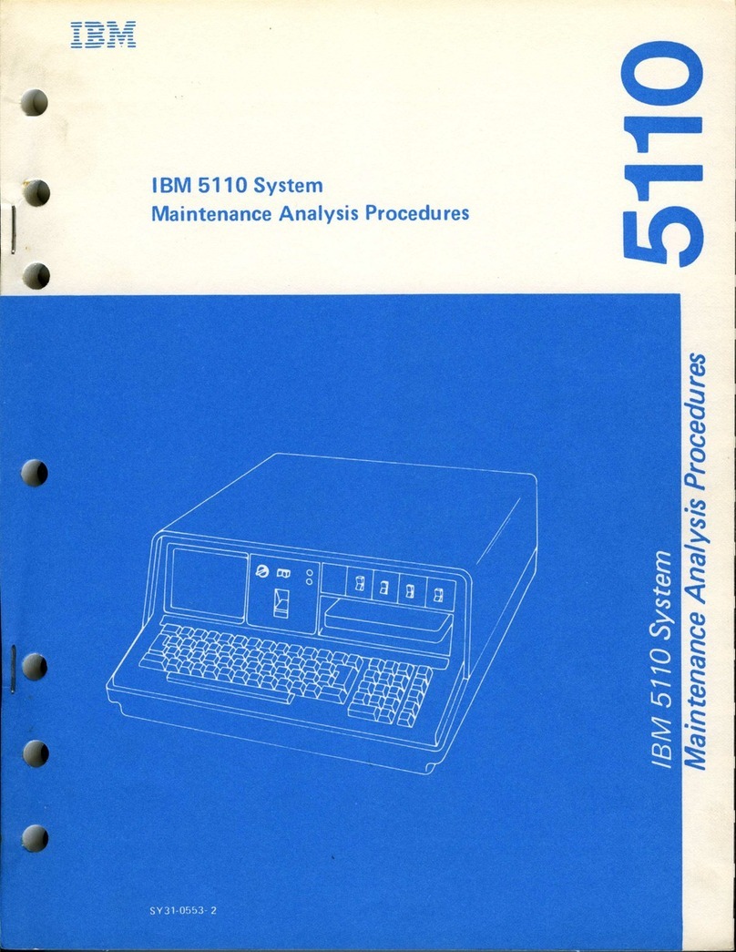
IBM 5251 Series Setup guide

-==:..-
-
-
--
SY31·0461·3
- ---,-
-
--
-
---
- --
---
--
..
-
-_.-
IBM 5251 Display Station
Models 1 and
11
, Maintenance Information Manual

-
-.-
-
--
SY31-0461-3
-
----
-
--
-
---
- --
-...,-
-
-..,-
-_.-
IBM
5251 Display Station
Models 1 and
11
Maintenance I
nformation
Manual

Preface
This maintenance
information
manual is
to
be used
for
servicing
the
IBM
5251
Models
1 and
11
Display
Station.
Customer
engineers using
this
manual are
assumed
to
have
completed
the course on
the
5251
Models
1 and
11
Display Station.
The maintenance
information
manual
(MIM)
has
two
major
sections:
maintenance and theory. Maintenance
includes locations, procedures, and
diagnostic
aids.
Theory
includes data
flow,
functional units, and features.
Definitions
of
terms
and abbreviations
that
are
not
common,
but
are used in the
MIM,
are in
the
Glossary
of
Terms and Abbreviations.
Setup
instructions
for
the 5251
Models
1 and
11
Display
Station
are in Appendix
A.
Note:
MIM
pages
1-5, 1-8, 1-27, 1-45, 1-48, 1-49, 1-77,
1-78,1-80,1-81,1-83,1-89,1-91,1-92,1-95,1-96,1-99,
1-100,1-103,3-2,
and
A-1
have
DANGER
and/or
CAUTION
notices.
If
desired, translate these notices and
write
your
own words on the blank lines provided on
these
pages.
Fourth
Edition
(July
1979)
Related
Publications
Related
information
can be
found
in
the
following
IBM
5250
Informaton
Display
System
manuals:
•
IBM
5250
Display System Reference Card,
GX21-9249
• IBM
5251
Display Station Models 1 and 11,
IBM
5252
Dual Display Station Operator's Guide,
GA21-9248
• IBM
5251
Display Station Models 1 and 11
Maintenance Analysis Procedures,
SY31-0571
• IBM
5256
Printer
Operator's Guide,
GA21-9260
•
IBM
5256
Printer
Maintenance
Information
Manual,
SY31-0462
•
IBM
5256
Printer
Maintenance Analysis Procedures,
SY31-0572
• IBM
5252
Dual Display Station Maintenance
Information Manual,
SY31-0492
• IBM
5252
Dual Display Station Maintenance Analysis
Procedures,
SY31-0584
•
IBM
5250
Information Display
System
Planning and
Site Preparation Guide,
GA21-9337
This
edition
has
important
changes.
It
obsoletes
SY31-0461-2
and
Technical
Newsletter
SN31-6259.
The changes are extensive and
the
manual
should
be
reviewed in
its
entlrety.
Use
this
publication
only
for
the
purpose
stated
in
the
Preface.
Publications
are
not
stocked
at
the
address
given
below.
Make
your
request
for
IBM
manuals
to
your
IBM
representative
or
to
the
IBM
branch
office
for
your
area.
This
publication
could
contain
errors.
Write
your
comments
on
the
form
at
the
back
of
this
manual.
If
the
form
has been removed, send
your
comments
to
IBM
Corporation,
Publications,
Department
245, Rochester,
Minnesota
55901.
IBM
may
use and
distribute
any
of
the
information
you
supply
in any
way
it
believes
appropriate
without
incurring
any
obligation
whatever.
You may,
of
course,
continue
to
use
the
information
you
supply.
©
Copyright
International
Business
Machines
Corporation
1977, 1978,
1979
iii

The 5251
Models
1 and
11
Display Stations have
the
following
specific DANGERs:
• Line voltage is present
at
the
power
supply and
the
display assembly.
• High voltage is present
at
the
cathode-ray
tube.
• The
cathode-ray
tube
could implode
if it
is
hit
or
if
it
falls.
• The green
wire
in
the
display assembly is
not
at
ground voltage.
iv
Safety

CE
SAFETY PRACTICES
All Customer Engineers are expected
to
take every safety
precaution possible and observe
the
following
safety practices
while
maintaining IBM equipment:
1.
You should
not
work
alone under hazardous conditions
or
around equipment
with
dangerous voltage. Always
advise
your
manager
if
you
MUST
work
alone.
2.
Remove all power, ac and dc,
when
removing or
assembling major components,
working
in immediate
areas
of
power
supplies, performing mechanical
inspection
of
power
supplies,
or
installing changes in
machine circuitry.
3.
After
turning
off
wall box
power
switch, lock
it
in
the
Off
position
or
tag
it
with
a
"Do
Not
Operate" tag,
Form 229-1266. Pull
power
supply cord whenever
possible.
4.
When
it
is
absolutely necessary
to
work
on equipment
having exposed operating mechanical parts
or
exposed
live electrical circuitry anywhere
in
the machine, observe
the
following
precautions:
a.
Another
person familiar
with
power
off
controls
must
be in immediate vicinity.
b. Do
not
wear
rings,
wrist
watches, chains, bracelets,
or
metal
cuff
links.
c.
Use
only
insulated pliers and screwdrivers.
d. Keep one hand in pocket.
e.
When
using
test
instruments, be certain
that
controls
are set correctly and
that
insulated probes
of
proper
capacity are used.
f. Avoid contacting ground potential (metal
floor
strips,
machine frames, etc.). Use suitable rubber mats,
purchased locally
if
necessary.
5.
Wear
safety glasses
when:
a.
Using a hammer
to
drive pins, riveting, staking, etc.
b. Power or hand drilling, reaming, grinding, etc.
c.
Using spring hooks, attaching springs.
d. Soldering,
wire
cutting, removing steel bands.
e.
Cleaning parts
with
solvents, sprays, cleaners,
chemicals, etc.
f. Performing any other
work
that
may be hazardous
to
your eyes. REMEMBER-THEY ARE YOUR
EYES.
6.
Follow special safety instructions when performing
specialized tasks, such as handling cathode ray tubes
and extremely high voltages. These instructions are
outlined
in
CEMs and
the
safety portion
of
the
maintenance manuals.
7. Do
not
use solvents, chemicals, greases,
or
oils
that
have
not
been approved
by
IBM.
8. Avoid using
tools
or
test
equipment
that
have
not
been
approved by
IBM.
9. Replace
worn
or
broken
tools
and
test
equipment.
10. Lift
by
standing
or
pushing up
with
stronger leg
muscles-this
takes strain
off
back muscles. Do
not
lift
any equipment
or
parts weighing over 60 pounds.
11
.
After
maintenance, restore all safety devices, such
as
guards, shields, signs, and grounding wires.
12. Each Customer Engineer is responsible
to
be certain
that
no
action on his part renders products unsafe
or
exposes customer personnel
to
hazards.
13. Place removed machine covers in a safe
out-of-the-way
place where
no
one can
trip
over them.
14. Ensure
that
all machine covers are in place before
returning machine
to
customer.
15.
Always
place
CE
tool kit
away
from
walk
areas
where
no
one can
trip
over it;
for
example, under desk
or
table.
16. Avoid touching moving mechanical parts
when
lubricating, checking
for
play, etc.
17.
When
using stroboscope,
do
not
touch
ANYTHING-it
may
be
moving.
18. Avoid wearing loose clothing
that
may be caught in
machinery. Shirt sleeves
must
be
left
buttoned
or
rolled
above the elbow.
19. Ties must be tucked
in
shirt or have a tie clasp
(preferably nonconductive) approximately 3 inches
from
end. Tie chains are
not
recommended.
20. Before starting equipment, make certain
fellow
CEs
and
customer personnel are
not
in a hazardous position.
21. Maintain good housekeeping
in
area
of
machine
while
performing and after completing maintenance.
Knowing
safety
rules
is
not
enough.
An
unsafe
act
will
inevitably
lead
to
an
accident.
Use
good
judgment-eliminate
unsafe
acts.
ARTIFICIAL RESPIRATION
General
Considerations
1. Start
Immediately-Seconds
Count
Do
not
move victim unless absolutely necessary
to
remove
from
danger. Do
not
wait
or
look
for
help
or
stop
to
loosen clothing,
warm
the victim,
or
apply
stimulants.
2.
Check
Mouth
for
Obstructions
Remove foreign objects. Pull tongue
forward.
3.
Loosen
Clothing-Keep
Victim
Warm
Take care
of
these items
after
victim
is breathing by
himself
or
when
help is available.
4. Remain in Position
After
victim revives, be ready
to
resume respiration
if
necessary.
5.
Call a
Doctor
Have someone
summon
medical aid.
6.
Don't
Give
Up
Continue
without
interruption until victim is breathing
without
help or is certainly dead.
Rescue
Breathing
for
Adults
1.
Place victim on his back immediately.
2.
Clear
throat
of
water,
food,
or
foreign matter.
3.
Tilt
head back
to
open air passage.
4.
Lift
jaw
up
to
keep tongue
out
of
air passage.
5.
Pinch nostrils
to
prevent air leakage
when
'You
blow.
6.
7.
8.
Blow
until you see chest rise.
Remove your lips and
allow
lungs
to
empty.
Listen
for
snoring and
gurglings-signs
of
throat
obstruction.
9. Repeat
mouth
to
mouth
breathing
10-20
times
a minute.
Continue rescue breathing until
victim
breathes
for
himself. .
Thumb and
finger positions Final
mouth-to-
mouth
position
v


SAFETY
..................
.
GLOSSARY
OF
TERMS
AND
ABBREVIATIONS
LEGEND
..................
.
USING
THE
IBM
5251
DISPLAY
STATION
MODELS
1
AND
11
MAINTENANCE
INFORMATION
MANUAL
Maintenance
Procedures Section
Location
Drawings
. . .
Maintenance
Procedures
Mini-MAPs
.....
.
Diagnostic
Aids
Preventive
Maintenance
Section .
Tools and
Test
Equipment Section
Theory Section .
Features Section
Appendixes
Index
MAINTENANCE
PROCEDURES
LOCATIONS
...
100
Front
View
.
101 Covers Open
102
Cable
Chart
.
103
Main
Planar Board and Card Locations
104
Logic Part Numbers . . . .
105
Main
Planar Board
Jumpers
COVERS
........
.
108
Display Station Covers . . .
109 Keyboard Covers . . . . .
CONTROL PANEL
AND
KEYLOCK
110
Control Panel . . . . . . .
111, 112,
113
Control Panel Cable
Mini-MAP
Conditions
After
Power On
Service
Aids
. . . . . .
114
Keylock
Mini-MAP
...
MAGNETIC
STRIPE READER .
115
Magnetic
Stripe Reader Voltage and Control
Mini-MAP
........
.
Conditions
After
Power On
Service
Aids
. . . . . . .
Tools
.........
.
116
Magnetic
Stripe
Reader Register 5
Mini-MAP
Conditions
after
Power On
Service
Aids
. . . . . . . . . . . . . . .
Tools
.................
.
117
Magnetic
Stripe Reader Registers 5 and 13
Mini-MAP
........
.
Conditions
After
Power On
Service
Aids
. . . . . . .
Tools
.....
c'
••••
118
Magnetic
Stripe Reader Card
Jumpering
119
Magnetic
Stripe
Reader Installation and Removal
Installation
.............
.
Removal
..............
.
120
Light Pen
Voltage
and Control
Mini-MAP
Conditions
After
Power
On . . . . . . .
iv
xi
xv
xvii
xvii
xvii
xvii
xvii
xvi
xvii
xvii
xvii
xvii
xviii
xviii
1-1
1-1
1-1
1-2
1-3
1-4
1-5
1-7
1-8
1-8
1-8
1-9
1-9
1-10
1-10
1-10
1-12
1-15
1-15
1-15
1-15
1-15
1-19
1-19
1-19
1-19
1-23
1-23
1-23
1-23
1-26
1-27
1-27
1-27
1-29
1-29
Service
Aids
. . . . . . . . . . . . . . .
Tools
.................
.
121 Light
Pen
Register and Control
Mini-MAP
Conditions
After
Power-On
Service
Aids
. . . . . . . . . . . . . . .
Tools
.................
.
122 Light
Pen
Register and Control
Mini-MAP
Conditions
After
Power On
Service
Aids
. . . . . . . . . .
Tools
............
.
123 Light Pen Tip
Switch
Mini-MAP
Service
Aids
. . . . . . . .
Tools
............
.
124
Light Pen Card
Jumpering
125 Light
Pen
Installation and Removal
Installation
Removal
KEYBOARD
130
Keyboard Locations
131 Keyboard RemovaI and Disassembly
Removal
Disassembly
Assembly
.
132
Cleaning
133
Key
Module.
Removal
Installation
134
Spacebar
Removal
Installation
135
Flyplate Replacement
136 Keyboard ID
Mini-MAP
Conditions
After
Power On
Service
Aids
. . . . . . .
Tools
.........
.
137
Keyboard Scan Code
Mini-MAP
Conditions
After
Power
On
Service
Aids
. . . . . . . . . .
Tools
............
.
138 Keyboard Voltage and
Strobe
Mini-MAP
Conditions
After
Power On
Service
Aids
. . . . . . . . .
Tools
...........
.
139 Keyboard Clicker
Mini-MAP.
Conditions
After
Power On
Service
Aids
. . . . . . . . .
Tools
...........
.
140
Keyboard Cable Check
Mini-MAP
Conditions
After
Power On
Service
Aids
. . . . . . . .
Tools
..........
.
141
Keyboard
paR
Mini-MAP
Conditions
After
Power On
Service
Aids
. . . . . .
Tools
........
.
142 Keyboard Identification
vi
Contents
1-29
1-29
1-33
1-33
1-33
1-33
1-37
1-37
1-37
1-37
1-41
1-41
1-41
1-45
1-45
1-45
1-47
1-47
1-48
1-48
1-48
1-48
1-48
1-49
1-49
1-49
1-50
1-50
1-50
1-50
1-52
1-52
1-52
1-52
1-54
1-54
1-54
1-54
1-57
1-57
1-57
1-57
1-62
1-62
1-62
1-62
1-64
1-64
1-64
1-64
1-66
1-66
1-66
1-66
1-68

143 Keyboard
Arrangement
. . .
Keyboard
Template
(GX21-9266)
Standard Keyboard Layout
Standard Keyboard Layout (Katakana)
Data-Entry Keyboard Layout (66 Keys)
Data-Entry Keyboard Layout (67 Keys)
Katakana Data-Entry Keyboard Layout (69)
144
Scan Code Table . . . . .
150 Display
Assembly
Locations
....
.
Top
View
..............
.
151 Display
Assembly
Removal and Replacement
Removal
.....
.
Replacement.
. . . .
DISPLAY
ADJUSTMENTS
152 Video
Adjustments
Brightness Limiter
Potentiometer
Adjustment
Contrast Control and Brightness
Control
Adjustments
. . . . . . . .
Video
Gain/Video
Drive
Potentiometer
Adjustment
. . . . . . . . . . . .
153 Vertical and Horizontal
Adjustments
Vertical
Adjustments
. .
Horizontal
Adjustments
. . .
154
Yoke
Adjustment
(150)
..
155 Centering
Adjustment
(150)
Factory
Adjustments.
. . . . .
Focus
Potentiometer
Adjustment
B+
Potentiometer
Adjustment
156 Raster . . . . . . .
Raster Check
....
. . . .
157 Display
Assembly
Cable
Mini-MAP
Conditions
After
Power
On
Service
Aids
. . . . . . .
Tools
.........
.
158 Display Screen Examples
SYSTEM CABLE . . . . . .
170
Customer System Cable Signal Quality Check
171 Internal System Cable and
Terminator
Switch
172 Typical Display
Station
Configuration
173
Station
Protector and Lightning Protector .
Station Protector . . . . . . .
Typical Installation . . . . . .
Typical Station Protector Board
Lightning Protector . . . . . .
174
Cable
Assembly
Procedures.
Assembly
of
Twinaxial
Cable
Assembly
of
Coaxial Cable
Twinaxial-Coaxial
Adapter
Adapter
Service Check
Cable Labeling . . . . . .
Tests
of
Cabling
After
Installation
POWER SUPPLY . . . . . . . . .
180
Power
Supply
Locations . . .
181 Power
Supply
Removal and Replacement
Removal
......
.
Replacement.
. . . . . . . . . .
182 Voltage Level Checks
.....
183
Power
Supply
Ripple Level Check
184
Power
Supply
Charts
US Power
Supply
. . . . . . . .
World
Trade
Power
Supply
185
Line
Cordi
Line Filter Removal and Replacement
187 Power
Supply
Fan
Removal and Relplacement
Removal
Replacement.
. . . . . . . . . . . . . . . .
1-69
1-69
1-69
1-69
1-70
1-70
1-71
1-73
1-75
1-76
1-77
1-77
1-77
1-78
1-78
1-78
1-78
1-78
1-78
1-79
1-79
1-79
1-80
1-80
1-80
1-80
1-81
1-81
1-83
1-83
1-83
1-83
1-86
1-89
1-89
1-89
1-90
1-91
1-91
1-91
1-91
1-92
1-94
1-94
1-96
1-97
1-97
1-97
1-97
1-98
1-98
1-99
1-99
1-99
1-100
1-101
1-101
1-101
1-102
1-103
1-103
1-103
1-103
188 Light
Pen
Power
Supply
Card
Removal and Replacement
1-103
Removal
1-103
Replacement .
1-103
DIAGNOSTIC
AIDS
1-104
200
Control Panel LEDs
1-104
Line Sync
1-104
Line Check
1-104
Internal Check
1-104
Storage Check
1-104
Ready
1-104
201
Status
Switch
1-105
202
Field
Attribute
Characters .
1-107
203
Display
Station
Operation
Overview
1-108
204
Power-On
Diagnostic
1-109
Power-On
Diagnostic
Flowchart
(Part 1
of
3)
1-109
Power-On
Diagnostic
Flowchart
(Part 2
of
3)
1-110
Power-On
Diagnostic
Flowchart
(Part 3
of
3) 1-111
205
Free
Key Operation
1-112
Free Key
Mode
Flowchart
1-112
206
Online Tests
1-113
Online
Tests
Overview
1-114
Online Tests Displays .
1-115
207
Sign-On Procedure
1-128
208
Error
History
Table
1-129
209
Error Codes .
1-130
Display
Station
Error Codes
1-130
Operator Error Codes
1-132
210
Diagnostic Display Locations
1-135
Cursor Display Positions
1-135
Power-On
Diagnostic
Display
1-135
212
Troubleshooting
Aids
1-136
PREVENTIVE
MAINTENANCE.
2-1
TOOLS
AND
TEST
EQUIPMENT
3-1
CE
General Logic Probe(Part
453212)
3-2
THEORY.
4-1
INTRODUCTION 4-1
System
Configuration
4-1
DATA
FLOW
4-3
FUNCTIONAL
UNITS
4-4
I/O
Adapter
Control
4-4
Keyboard
4-5
Clicker
4-5
Keyboard
Identification
4-5
Display
Adapter
.
4-6
Buffering and. Displaying
4-7
Control Panel .
4-8
Display Screen
4-9
Field
Attributes
4-9
Display Screen
Indicators
4-9
Cable
Adapter
4-9
The
16-Bit
Frame
4-9
Transmission Sequences 4-11
Commands
4-12
Response Frame
4-14
Interface
4-16
Data Transfer
4-17
Microprocessing
Unit
(MPU)
4-18
Read/Write
Storage
4-18
Internal Processing Queue
4-18
Control Registers .
4-19
Contents
vi i

viii
FEATURES.
5-1
Keylock
Feature.
5-1
Cable Thru Feature 5-2
Magnetic
Stripe Reader Feature . 5-3
Read Data
Word
5-4
Selector Light
or
Pen
Feature 5-5
Theory
of
Operation 5-5
APPENDIX
A. DISPLAY
STATION
SETUP
INSTRUCTIONS
.
A-1
SETUP INSTRUCTIONS-SECTION 1 A-1
SETUP INSTRUCTIONS-SECTION 2
A-2
APPENDIX
B.
SELF-CHECK
FEATURE.
B-1
Self-Check Feature 8-1
Computing the Self-Check Digit 8-1
INDEX.
X-1

ix

x
This
page
is
intentionally
left
blank.

p.f:
Microfarad.
activity:
Action or process.
addr:
Address.
alpha:
Alphabetic.
ALU:
Arithmetic logic unit.
amplifier:
A device
that
increases a voltage
or
a signal
to
a usable level.
anode:
A positive terminal
of
a diode.
arithmetic:
The adding, subtracting, multiplying, or
dividing
of
two
or more numbers.
attribute:
A characteristic
that
controls
how
data is
displayed on the display screen. For example, the
attributes
of
a display field include blinking, high
intensity, and reverse image.
blink
attribute:
An attribute
of
a display field
that
causes the characters
to
flash.
brightness
limiter
potentiometer:
A potentiometer
that
prevents
too
much brightness. See reference 150.
buffer:
A temporary storage area.
Cable
Thru
feature:
A special feature
that
permits
multiple display stations
or
printers
to
be attached
serially
to
a system cable.
callout:
A character used
to
identify a particular portion
of
an
illustration.
capacitive:
Having capacitance.
cathode:
A negative terminal
of
a diode.
char:
Character.
character
matrix:
A part
of
the display screen
character
window.
The character matrix is 16
dots
high
by 8
dots
wide.
••
.,
..
. . .
Glossary
of
Tenns
and
Abbreviations
character
window:
A part
of
the
display screen
that
is
24
dots
high
by
10
dots
wide
and includes
the
character
matrix.
clicker:
A solenoid in the keyboard
that
makes a sound
after each keyboard character has been received by the
display station.
Cmd
key:
The command key on the keyboard
that
is
used
to
select command functions.
column
separator:
A vertical bar in a field
of
data
that
separates all characters in
that
field.
command
function
keys:
The
14
keys on the
top
row
of
the display station keyboard
that
are used
with
the
Cmd (command) key
to
request functions.
cont:
Controller.
Contrast
control:
The device
that
changes the contrast.
See reference 100.
controller:
A device
that
controls the operation
of
one
or
more input
or
output
devices.
data
stream:
A continuing
flow
of
data.
diag:
Diagnostic.
driver:
A source
that
sends (drives) a signal
from
one
location
to
another. See reference 212.
dual:
Having
two
similar parts.
Dup
key:
The key on the keyboard
that
is used
to
duplicate a field
from
a preceding field.
EOM:
End
of
message.
end-of-message
delimiteJ:
A
111
in the station ID field
that
indicates the last frame
of
a message block.
EOQ:
End
of
queue.
ERAP: Error recording analysis procedures.
xi

field
attribute:
The control characters
that
describe a
displayed field. For example, a display field can be
intensified, reversed, underscored,
or
made
to
blink.
flyplate:
The
bottom
of
a key module. See reference
135.
FRU: Field-replaceable unit.
hex:
Hexadecimal.
HH:MM:SS:
Hours, minutes, and seconds.
10: Identification.
implode:
To
break inward suddenly.
Ins
key:
The key on the keyboard
that
is used
to
select
the insert mode.
IPL: Initial program load.
KBD:
Keyboard.
key
stem:
The connecting part between the key
top
and
the key module. See reference 135.
Keylock
feature:
A feature
with
a lock and key
that
restricts
the
use
of
the display station.
keystroke:
The action
of
pressing a key on the
keyboard.
LED:
Light-emitting
diode.
linearity:
The size
of
displayed characters
of
equal
width.
line
turnaround:
The time between
the
reception
of
the
last bit
of
a
frame
by a
work
station and the start
of
transmission
by
that
same
work
station.
LP: Light pen.
LRC: Longitudinal redundancy check.
main
planar:
The basic printed circuit electronic board
used in the display station.
make/break
key:
A key
that
generates a scan code
when the key is pressed and when
it
is released.
mandatory:
Something
that
must
be done
or
must
be
present.
menu:
A list
of
options
that
can be selected.
microfarad:
One millionth part
of
a farad.
microinstruction:
A basic
or
elementary machine
instruction.
microprocessing:
Operations performed by the MPU.
xii
microprocessing
unit
(MPU):
A processing unit
that
is
microprogram controlled and performs internal machine
operations. The MPU receives data, controls the display
of
data, and controls the
flow
of
information
to
and
from
the
controller.
microprogram:
A program
that
uses microinstructions
to
carry
out
system operations.
mini-MAP:
A maintenance analysis procedure
that
is
located in
the
maintenance information manual. A
mini-MAP
continues the failure analysis
after
one
of
the
other
MAPs
has located
the
area
that
is failing.
MPU:
Microprocessing unit.
MSR:
Magnetic
Stripe Reader feature.
mm:
Millimeter.
ms:
Millisecond.
msg:
Message.
MSIPL:
Main storage initial program load.
multiframe
response:
More
than one frame
of
data is
being sent.
N/C:
Pertains
to
a switch setting; normally closed.
N/O:
Pertains
to
a switch setting; normally open.
null:
A hex character composed
of
all zeros; this
character occupies a position in
the
buffer
and is
displayed as a blank.
online
test:
A series
of
tests
that
can be requested
from
the system
after
power
on and before
sign-on.
See reference 206.

option:
One
of
the items listed on a display screen
menu.
overview:
A
short
description.
P-P:
Peak-to-peak.
pc:
Printed circuit.
planar:
See main
planar.-
PM: Preventive maintenance.
poll:
A method the controller uses
to
determine
if
a
display station is ready
to
send
or
receive data.
POR: Power on reset.
port:
The place where a cable is connected
to
a
machine.
protector:
A device
that
aids in preventing injuries
to
persons or damage
to
machines.
R/D:
Receiver/driver.
raster:
The image on the CRT
that
is made by the
action
of
the
CRT electron beam as
it
scans across the
area
of
the
CRT where data is displayed. Normally, the
intensity
of
the raster is
not
high enough
to
be visible.
However,
the
raster can be displayed
if
you install a
raster check jumper.
read-only
storage
(ROS): A storage area in the
MPU
from
which data can be read
but
not
changed.
read/write
storage:
A storage area in the MPU
that
stores information
for
later use; the information can be
changed
by
the MPU.
receivers:
Those parts
that
accept data
or
voltages.
refresh:
To
continuously redisplay data on the display
screen
to
prevent the data
from
fading
out;
the display
adapter refreshes the data.
regen
buffer:
An
area in read/
write
storage where data
is stored before
it
is displayed.
register:
A storage device or circuit
that
stores those
limited parts
of
data needed by the system
to
execute
input/
output, storage, processing, and control
operations.
related:
Having a
common
use.
required:
See mandatory.
resolution:
The visual quality
of
display screen data.
retaining
ears:
The projections located on the
bottom
of
a key module; these projections hold the module
to
the frame. See reference 133.
retrace
lines:
The lines
that
appear on the display
screen when the display adapter returns
the
sweep
to
the upper
left
corner
of
the display screen. Retrace lines
are normally blanked out. See reference 156.
retry:
To repeatedly send frames
of
information until
the frames are received
without
an
error by
the
display
station; the controller sends the frames.
ripple:
Small waves present on DC voltages.
ripple
level:
A measurement
of
the AC voltage carried
on the
DC
voltage.
rolling:
Pertains
to
movement
on a display screen;
the
movement can be either horizontal, vertical,
or
a
combination
of
both.
ROS: Read-only storage.
rt
adj:
Right adjust.
serdes:
Serializer/ deserializer.
serializer/deserializer
(serdes): A register
that
is used
to
send and receive data between
the
display station
and
the
controller.
setup:
To prepare a device
for
operation.
sign-on:
A logon procedure performed at a display
station;
the
procedure can include entering
the
sign-on
command, a password,
or
other user specified security
information.
slot:
A
narrow
opening
or
groove.
SOM:
Start
of
message.
stabilizer:
A rod on
the
Spacebar. See reference 134.
xiii

stat
addr:
Station address.
stem:
See key stem.
stiffener:
A
part
used
to
supply
rigidity
to
a logic card
or
planar.
storm:
Electrical discharges in
the
air.
strain
relief
cable:
A cable
that
supports
the
planar.
SVCS:
Services.
SYS:
System.
Sys
Req
key:
A key
that
is used
to
send a request
directly
to
the system.
taper:
Increasing
in
size
toward
one end.
TB:
Terminal block.
Terminator
switch:
A
switch
used
to
terminate
the
customer system cable
at
the
last display station
or
printer in a series. This
switch
is a part
of
the
Cable
Thru feature on a display station.
theory:
A section
of
this
manual
that
includes data
flow,
functional units, and features.
transfer:
To
move
from
one person, place,
or
thing
to
another.
twinaxial
cable:
A shielded
twisted-pair
cable
that
connects a display station
or
printer
to
a controller.
typamatic
key:
A
repeat-action
key on the keyboard.
undefined:
The meaning is
not
known
or
described.
underscore:
A line under all positions
of
a field.
Underscore is controlled
by
an attribute.
US:
United States.
Vac:
Volts alternating current.
Vdc:
Volts direct current.
verification:
Testing
an
operation
or
machine.
video:
Pertains
to
the display screen image.
YY
/MM/DD:
Year,
month,
and day.
xiv

Legend
The
following
symbols
are u
sed in
flowcharts
and
figures
throughout
this
manual.
i'
Zener
Diode
CJ
Display Screen
--of- Diode
( ) Start and End
~~
Capacitor
of
Flowchart
V Off-Page
J,-J-
Ground
Connector
0 On-Page
]111
[
Connector
Transformer
0 Decision
Block
p~
Relay
C
Comment
.-r
Contact (relay
Block
not
energized)
L
D
Information
~
Contact (relay
Block
energized)
L
-{>
Logic (indicates
Resistor
signal
direction)
Driver
"-',
Jumper
"
0--
--0
i2=r
Logic
Driver
IRecei'ver
-B- Relay Driver
H Detector
Legend 5251
MIM
xv

xvi
This
page
is
intentionally
left
blank.

Using
the
IBM
5251 Display
Station
Models
1 and
11
Maintenance
Information
Manual
The information in this
MIM
is
to
be used
as
reference
material when you are diagnosing machine failures. This
MIM
contains a Maintenance Procedures section, a
Preventive Maintenance section, a Tools and Test
Equipment section, a Theory section, and a Features
section. Appendixes give general information (such
as
setup procedures)
that
is not directly related
to
the
maintenance
of
the 5251 Models 1 and
11
Display
Station.
The
format
for
page numbering is
X-VYY.Z.
X is
the
section number, YYY is the page number, and Z
(although
not
normally used) is the number used
for
expansion when
it
is not practical
to
give
new
numbers
to
all pages.
Three-digit
reference numbers are assigned
to
location
drawings and maintenance procedures
that
are referred
to
in the MAPs. For example, 130 indicates the
keyboard locations
of
the display station.
MAINTENANCE
PROCEDURES
SECTION
The Maintenance Procedures section contains location
drawings, maintenance procedures,
mini-MAPs,
and
diagnostic aids
for
repairing, installing,
or
diagnosing the
failing FRUs
(field-
replaceable units).
Location
Drawings
Location drawings
show
the position
of
the parts in the
display station.
Maintenance
Procedures
Maintenance procedures contain removal, replacement,
and adjustment procedures. All procedures and
drawings have assigned
three-digit
reference numbers.
Mini-MAPs
You are sent
to
mini-MAPs
to
continue the failure
analysis
to
locate a failing
field-
replaceable unit.
In general,
mini-
MAPs
provide you
with
three levels
of
information:
1.
2.
A figure showing
the
circuit line names and pin
numbers.
A description
of
the circuit and
how
it
can be
tested.
3.
A detailed guide
that
uses the yes and no path
of
questions
that
you can
follow
to
isolate
the
failure.
You can select the level
of
information you need
to
locate a failing field-replaceable unit.
Diagnostic
Aids
Diagnostic Aids describe diagnostic programs,
how
to
use
them,
and
what
is
available when they
are
in
control. To aid in diagnosing machine failures in
more detail, a list
of
error conditions
is
included.
PREVENTIVE
MAINTENANCE
SECTION
The Preventive Maintenance section describes any
preventive maintenance required by the display station.
TOOLS
AND
TEST
EQUIPMENT
SECTION
The Tools and Test Equipment section describes the tools
that
are needed
to
service the display station.
THEORY
SECTION
The Theory section describes the functional units and
features. These descriptions are preceded by a
view
of
the system
that
gives you a general idea
of
the
complete operation and
how
each function
or
feature
relates
to
the
operation.
FEATURES
SECTION
The Features section describes the features
that
are
available
with
the 5251 Models 1 and
11
Display
Station.
Using the
MIM
5251
MIM
xvii

APPENDIXES
Appendix A contains the setup procedures required
to
make a
new
display station operational. Appendix B
explains the operation
of
the
Self-Check
feature.
Self-Check
is a host system feature.
INDEX
The index is a detailed list
of
all
the
material contained
in the
MIM.
xviii

100
locations
100 FRONT
VIEW
Display
Screen
--
--
--
--
--
--
--
--
--
--
--
:::===
--
SYstem
Cable-
__
~~
_____
;-"""
Connector
(socket
1)
Address SWitches
•
•••
. .
.'
....
Maintenance
Procedures
Bezel
Display
Screen
Indicators
Connector
(socket 2) Access Panel Cover
Keyboard Cable
Connector
Maintenance Procedures 5251
MIM
1-1

1-2
101 COVERS OPEN
Main
Planar Board
Display Assembly
------
The covers are
sh
. own
pivoted open.
Power Supply
Line Filter
This manual suits for next models
2
Table of contents
Other IBM Desktop manuals

IBM
IBM Power775 Manual

IBM
IBM BRUGERVEJLEDNING 8184 Technical document

IBM
IBM HC10 - BladeCenter - 7996 User manual

IBM
IBM NetVista Owner's manual

IBM
IBM PS/1 Owner's manual

IBM
IBM NetVista X40 Instruction Manual

IBM
IBM 2179 Owner's manual

IBM
IBM NetVista X40 User manual

IBM
IBM NetVista A22p User manual

IBM
IBM THINKPAD R50E - Owner's manual