IBM 9223-22H User manual

Power Systems
Adapter placement for the 5105-22E,
9008-22L, 9009-22A, 9009-22G,
9223-22H, or 9223-22S
IBM

Note
Before using this information and the product it supports, read the information in “Safety notices” on
page v, “Notices” on page 27, the IBM Systems Safety Notices manual, G229-9054, and the IBM
Environmental Notices and User Guide, Z125–5823.
This edition applies to IBM® Power Systems servers that contain the POWER9™ processor and to all associated models.
© Copyright International Business Machines Corporation 2018, 2021.
US Government Users Restricted Rights – Use, duplication or disclosure restricted by GSA ADP Schedule Contract with
IBM Corp.

Contents
Safety notices........................................................................................................v
Adapter placement................................................................................................1
Adapter slot descriptions for the system.................................................................................................... 1
Adapter placement rules and slot priorities for the system....................................................................... 6
Adapter placement rules and slot priorities for the EMX0 PCIe Gen3 I/O expansion drawer................ 17
Related procedures for adapter placement..............................................................................................24
Finding the current system conguration in IBM i.............................................................................. 24
Notices................................................................................................................27
Accessibility features for IBM Power Systems servers............................................................................ 28
Privacy policy considerations ................................................................................................................... 29
Trademarks................................................................................................................................................ 29
Electronic emission notices.......................................................................................................................29
Class A Notices.....................................................................................................................................29
Class B Notices.....................................................................................................................................33
Terms and conditions.................................................................................................................................35
iii

iv

Safety notices
Safety notices may be printed throughout this guide:
•DANGER notices call attention to a situation that is potentially lethal or extremely hazardous to people.
•CAUTION notices call attention to a situation that is potentially hazardous to people because of some
existing condition.
•Attention notices call attention to the possibility of damage to a program, device, system, or data.
World Trade safety information
Several countries require the safety information contained in product publications to be presented in
their national languages. If this requirement applies to your country, safety information documentation is
included in the publications package (such as in printed documentation, on DVD, or as part of the product)
shipped with the product. The documentation contains the safety information in your national language
with references to the U.S. English source. Before using a U.S. English publication to install, operate, or
service this product, you must rst become familiar with the related safety information documentation.
You should also refer to the safety information documentation any time you do not clearly understand any
safety information in the U.S. English publications.
Replacement or additional copies of safety information documentation can be obtained by calling the IBM
Hotline at 1-800-300-8751.
German safety information
Das Produkt ist nicht für den Einsatz an Bildschirmarbeitsplätzen im Sinne § 2 der
Bildschirmarbeitsverordnung geeignet.
Laser safety information
IBM servers can use I/O cards or features that are ber-optic based and that utilize lasers or LEDs.
Laser compliance
IBM servers may be installed inside or outside of an IT equipment rack.
DANGER: When working on or around the system, observe the following precautions:
Electrical voltage and current from power, telephone, and communication cables are hazardous. To
avoid a shock hazard: If IBM supplied the power cord(s), connect power to this unit only with the
IBM provided power cord. Do not use the IBM provided power cord for any other product. Do not
open or service any power supply assembly. Do not connect or disconnect any cables or perform
installation, maintenance, or reconguration of this product during an electrical storm.
• The product might be equipped with multiple power cords. To remove all hazardous
voltages, disconnect all power cords. For AC power, disconnect all power cords from their AC power
source. For racks with a DC power distribution panel (PDP), disconnect the customer’s DC power source
to the PDP.
• When connecting power to the product ensure all power cables are properly connected. For racks with
AC power, connect all power cords to a properly wired and grounded electrical outlet. Ensure that the
outlet supplies proper voltage and phase rotation according to the system rating plate. For racks with a
DC power distribution panel (PDP), connect the customer’s DC power source to the PDP. Ensure that the
proper polarity is used when attaching the DC power and DC power return wiring.
• Connect any equipment that will be attached to this product to properly wired outlets.
© Copyright IBM Corp. 2018, 2021 v

• When possible, use one hand only to connect or disconnect signal cables.
• Never turn on any equipment when there is evidence of re, water, or structural damage.
• Do not attempt to switch on power to the machine until all possible unsafe conditions are corrected.
• When performing a machine inspection: Assume that an electrical safety hazard is present. Perform
all continuity, grounding, and power checks specied during the subsystem installation procedures to
ensure that the machine meets safety requirements. Do not attempt to switch power to the machine
until all possible unsafe conditions are corrected. Before you open the device covers, unless instructed
otherwise in the installation and conguration procedures: Disconnect the attached AC power cords,
turn off the applicable circuit breakers located in the rack power distribution panel (PDP), and
disconnect any telecommunications systems, networks, and modems.
• Connect and disconnect cables as described in the following procedures when installing, moving, or
opening covers on this product or attached devices.
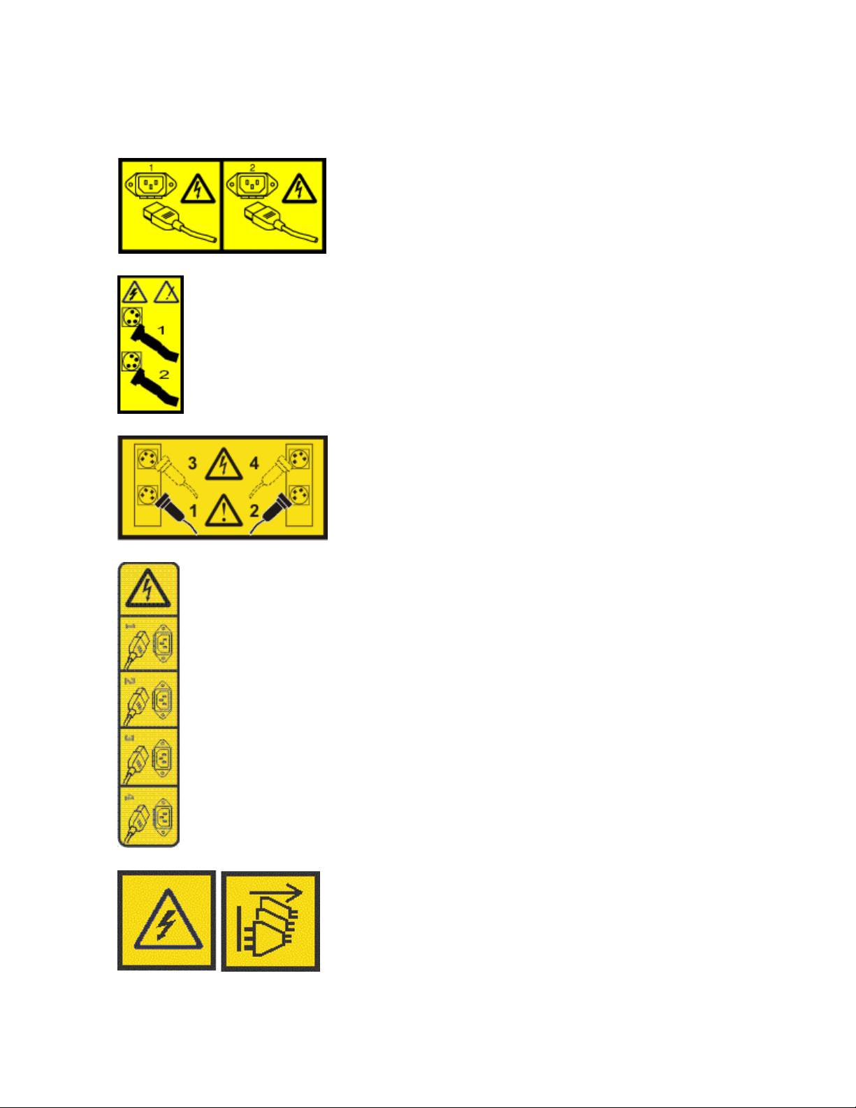
To Disconnect: 1) Turn off everything (unless instructed otherwise). 2) For AC power, remove the power
cords from the outlets. 3) For racks with a DC power distribution panel (PDP), turn off the circuit
breakers located in the PDP and remove the power from the Customer's DC power source. 4) Remove
the signal cables from the connectors. 5) Remove all cables from the devices.
To Connect: 1) Turn off everything (unless instructed otherwise). 2) Attach all cables to the devices. 3)
Attach the signal cables to the connectors. 4) For AC power, attach the power cords to the outlets. 5)
For racks with a DC power distribution panel (PDP), restore the power from the Customer's DC power
source and turn on the circuit breakers located in the PDP. 6) Turn on the devices.
• Sharp edges, corners and joints may be present in and around the system. Use
care when handling equipment to avoid cuts, scrapes and pinching. (D005)
(R001 part 1 of 2):
DANGER: Observe the following precautions when working on or around your IT rack system:
• Heavy equipment–personal injury or equipment damage might result if mishandled.
• Always lower the leveling pads on the rack cabinet.
• Always install stabilizer brackets on the rack cabinet if provided, unless the earthquake option is
to be installed.
• To avoid hazardous conditions due to uneven mechanical loading, always install the heaviest
devices in the bottom of the rack cabinet. Always install servers and optional devices starting
from the bottom of the rack cabinet.
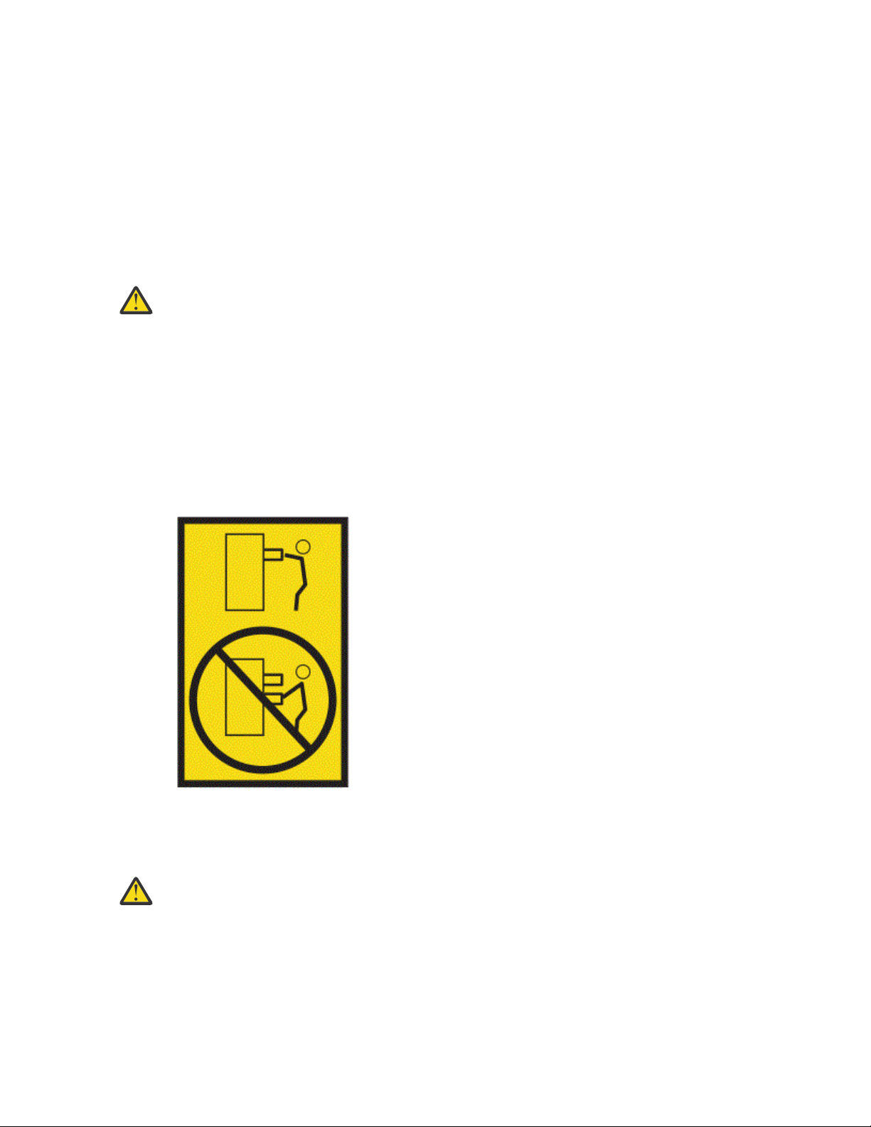
• Rack-mounted devices are not to be used as shelves or work spaces. Do not place objects on top
of rack-mounted devices. In addition, do not lean on rack mounted devices and do not use them
to stabilize your body position (for example, when working from a ladder).
• Stability hazard:
– The rack may tip over causing serious personal injury.
– Before extending the rack to the installation position, read the installation instructions.
– Do not put any load on the slide-rail mounted equipment mounted in the installation position.
– Do not leave the slide-rail mounted equipment in the installation position.
• Each rack cabinet might have more than one power cord.
– For AC powered racks, be sure to disconnect all power cords in the rack cabinet when directed
to disconnect power during servicing.
viPower Systems: Adapter placement for the 5105-22E, 9008-22L, 9009-22A, 9009-22G, 9223-22H, or
9223-22S

– For racks with a DC power distribution panel (PDP), turn off the circuit breaker that controls
the power to the system unit(s), or disconnect the customer’s DC power source, when directed
to disconnect power during servicing.
• Connect all devices installed in a rack cabinet to power devices installed in the same rack
cabinet. Do not plug a power cord from a device installed in one rack cabinet into a power device
installed in a different rack cabinet.
• An electrical outlet that is not correctly wired could place hazardous voltage on the metal parts
of the system or the devices that attach to the system. It is the responsibility of the customer to
ensure that the outlet is correctly wired and grounded to prevent an electrical shock. (R001 part
1 of 2)
(R001 part 2 of 2):
CAUTION:
• Do not install a unit in a rack where the internal rack ambient temperatures will exceed the
manufacturer's recommended ambient temperature for all your rack-mounted devices.
• Do not install a unit in a rack where the air flow is compromised. Ensure that air flow is not
blocked or reduced on any side, front, or back of a unit used for air flow through the unit.
• Consideration should be given to the connection of the equipment to the supply circuit so that
overloading of the circuits does not compromise the supply wiring or overcurrent protection.
To provide the correct power connection to a rack, refer to the rating labels located on the
equipment in the rack to determine the total power requirement of the supply circuit.
•(For sliding drawers.) Do not pull out or install any drawer or feature if the rack stabilizer brackets
are not attached to the rack or if the rack is not bolted to the floor. Do not pull out more than one
drawer at a time. The rack might become unstable if you pull out more than one drawer at a time.
•(For xed drawers.) This drawer is a xed drawer and must not be moved for servicing unless
specied by the manufacturer. Attempting to move the drawer partially or completely out of the
rack might cause the rack to become unstable or cause the drawer to fall out of the rack. (R001
part 2 of 2)
CAUTION: Removing components from the upper positions in the rack cabinet improves rack
stability during relocation. Follow these general guidelines whenever you relocate a populated rack
cabinet within a room or building.
• Reduce the weight of the rack cabinet by removing equipment starting at the top of the rack
cabinet. When possible, restore the rack cabinet to the conguration of the rack cabinet as you
received it. If this conguration is not known, you must observe the following precautions:
– Remove all devices in the 32U position and above.
– Ensure that the heaviest devices are installed in the bottom of the rack cabinet.
Safety noticesvii

– Ensure that there are little-to-no empty U-levels between devices installed in the rack cabinet
below the 32U level, unless the received conguration specically allowed it.
• If the rack cabinet you are relocating is part of a suite of rack cabinets, detach the rack cabinet
from the suite.
• If the rack cabinet you are relocating was supplied with removable outriggers they must be
reinstalled before the cabinet is relocated.
• Inspect the route that you plan to take to eliminate potential hazards.
• Verify that the route that you choose can support the weight of the loaded rack cabinet. Refer to
the documentation that comes with your rack cabinet for the weight of a loaded rack cabinet.
• Verify that all door openings are at least 760 x 2083 mm (30 x 82 in.).
• Ensure that all devices, shelves, drawers, doors, and cables are secure.
• Ensure that the four leveling pads are raised to their highest position.
• Ensure that there is no stabilizer bracket installed on the rack cabinet during movement.
• Do not use a ramp inclined at more than 10 degrees.
• When the rack cabinet is in the new location, complete the following steps:
– Lower the four leveling pads.
– Install stabilizer brackets on the rack cabinet or in an earthquake environment bolt the rack to
the floor.
– If you removed any devices from the rack cabinet, repopulate the rack cabinet from the lowest
position to the highest position.
• If a long-distance relocation is required, restore the rack cabinet to the conguration of the rack
cabinet as you received it. Pack the rack cabinet in the original packaging material, or equivalent.
Also lower the leveling pads to raise the casters off of the pallet and bolt the rack cabinet to the
pallet.
(R002)
(L001)
DANGER: Hazardous voltage, current, or energy levels are present inside any component that has
this label attached. Do not open any cover or barrier that contains this label. (L001)
(L002)
DANGER: Rack-mounted devices are not to be used as shelves or work spaces. Do not place
objects on top of rack-mounted devices. In addition, do not lean on rack-mounted devices and do
not use them to stabilize your body position (for example, when working from a ladder). Stability
hazard:
• The rack may tip over causing serious personal injury.
• Before extending the rack to the installation position, read the installation instructions.
viiiPower Systems: Adapter placement for the 5105-22E, 9008-22L, 9009-22A, 9009-22G, 9223-22H, or
9223-22S

• Do not put any load on the slide-rail mounted equipment mounted in the installation position.
• Do not leave the slide-rail mounted equipment in the installation position.
(L002)
(L003)
or
or
or
or
Safety noticesix

DANGER: Multiple power cords. The product might be equipped with multiple AC power cords
or multiple DC power cables. To remove all hazardous voltages, disconnect all power cords and
power cables. (L003)
(L007)
CAUTION: A hot surface nearby. (L007)
(L008)
CAUTION: Hazardous moving parts nearby. (L008)
All lasers are certied in the U.S. to conform to the requirements of DHHS 21 CFR Subchapter J for class
1 laser products. Outside the U.S., they are certied to be in compliance with IEC 60825 as a class 1 laser
product. Consult the label on each part for laser certication numbers and approval information.
CAUTION: This product might contain one or more of the following devices: CD-ROM drive, DVD-
ROM drive, DVD-RAM drive, or laser module, which are Class 1 laser products. Note the following
information:
• Do not remove the covers. Removing the covers of the laser product could result in exposure to
hazardous laser radiation. There are no serviceable parts inside the device.
• Use of the controls or adjustments or performance of procedures other than those specied
herein might result in hazardous radiation exposure.
(C026)
xPower Systems: Adapter placement for the 5105-22E, 9008-22L, 9009-22A, 9009-22G, 9223-22H, or
9223-22S

CAUTION: Data processing environments can contain equipment transmitting on system links with
laser modules that operate at greater than Class 1 power levels. For this reason, never look into
the end of an optical ber cable or open receptacle. Although shining light into one end and looking
into the other end of a disconnected optical ber to verify the continuity of optic bers may not
injure the eye, this procedure is potentially dangerous. Therefore, verifying the continuity of optical
bers by shining light into one end and looking at the other end is not recommended. To verify
continuity of a ber optic cable, use an optical light source and power meter. (C027)
CAUTION: This product contains a Class 1M laser. Do not view directly with optical instruments.
(C028)
CAUTION: Some laser products contain an embedded Class 3A or Class 3B laser diode. Note the
following information:
• Laser radiation when open.
• Do not stare into the beam, do not view directly with optical instruments, and avoid direct
exposure to the beam. (C030)
(C030)
CAUTION: The battery contains lithium. To avoid possible explosion, do not burn or charge the
battery.
Do Not:
• Throw or immerse into water
• Heat to more than 100 degrees C (212 degrees F)
• Repair or disassemble
Exchange only with the IBM-approved part. Recycle or discard the battery as instructed by
local regulations. In the United States, IBM has a process for the collection of this battery. For
information, call 1-800-426-4333. Have the IBM part number for the battery unit available when
you call. (C003)
CAUTION: Regarding IBM provided VENDOR LIFT TOOL:
• Operation of LIFT TOOL by authorized personnel only.
• LIFT TOOL intended for use to assist, lift, install, remove units (load) up into rack elevations. It is
not to be used loaded transporting over major ramps nor as a replacement for such designated
tools like pallet jacks, walkies, fork trucks and such related relocation practices. When this is not
practicable, specially trained persons or services must be used (for instance, riggers or movers).
• Read and completely understand the contents of LIFT TOOL operator's manual before using.
Failure to read, understand, obey safety rules, and follow instructions may result in property
damage and/or personal injury. If there are questions, contact the vendor's service and support.
Local paper manual must remain with machine in provided storage sleeve area. Latest revision
manual available on vendor's web site.
• Test verify stabilizer brake function before each use. Do not over-force moving or rolling the LIFT
TOOL with stabilizer brake engaged.
• Do not raise, lower or slide platform load shelf unless stabilizer (brake pedal jack) is fully
engaged. Keep stabilizer brake engaged when not in use or motion.
• Do not move LIFT TOOL while platform is raised, except for minor positioning.
• Do not exceed rated load capacity. See LOAD CAPACITY CHART regarding maximum loads at
center versus edge of extended platform.
• Only raise load if properly centered on platform. Do not place more than 200 lb (91 kg) on edge
of sliding platform shelf also considering the load's center of mass/gravity (CoG).
• Do not corner load the platforms, tilt riser, angled unit install wedge or other such accessory
options. Secure such platforms -- riser tilt, wedge, etc options to main lift shelf or forks in all four
(4x or all other provisioned mounting) locations with provided hardware only, prior to use. Load
objects are designed to slide on/off smooth platforms without appreciable force, so take care not
Safety noticesxi

to push or lean. Keep riser tilt [adjustable angling platform] option flat at all times except for nal
minor angle adjustment when needed.
• Do not stand under overhanging load.
• Do not use on uneven surface, incline or decline (major ramps).
• Do not stack loads.
• Do not operate while under the influence of drugs or alcohol.
• Do not support ladder against LIFT TOOL (unless the specic allowance is provided for one
following qualied procedures for working at elevations with this TOOL).
• Tipping hazard. Do not push or lean against load with raised platform.
• Do not use as a personnel lifting platform or step. No riders.
• Do not stand on any part of lift. Not a step.
• Do not climb on mast.
• Do not operate a damaged or malfunctioning LIFT TOOL machine.
• Crush and pinch point hazard below platform. Only lower load in areas clear of personnel and
obstructions. Keep hands and feet clear during operation.
• No Forks. Never lift or move bare LIFT TOOL MACHINE with pallet truck, jack or fork lift.
• Mast extends higher than platform. Be aware of ceiling height, cable trays, sprinklers, lights, and
other overhead objects.
• Do not leave LIFT TOOL machine unattended with an elevated load.
• Watch and keep hands, ngers, and clothing clear when equipment is in motion.
• Turn Winch with hand power only. If winch handle cannot be cranked easily with one hand, it
is probably over-loaded. Do not continue to turn winch past top or bottom of platform travel.
Excessive unwinding will detach handle and damage cable. Always hold handle when lowering,
unwinding. Always assure self that winch is holding load before releasing winch handle.
• A winch accident could cause serious injury. Not for moving humans. Make certain clicking sound
is heard as the equipment is being raised. Be sure winch is locked in position before releasing
handle. Read instruction page before operating this winch. Never allow winch to unwind freely.
Freewheeling will cause uneven cable wrapping around winch drum, damage cable, and may
cause serious injury.
• This TOOL must be maintained correctly for IBM Service personnel to use it. IBM shall inspect
condition and verify maintenance history before operation. Personnel reserve the right not to use
TOOL if inadequate. (C048)
Power and cabling information for NEBS (Network Equipment-Building System)
GR-1089-CORE
The following comments apply to the IBM servers that have been designated as conforming to NEBS
(Network Equipment-Building System) GR-1089-CORE:
The equipment is suitable for installation in the following:
• Network telecommunications facilities
• Locations where the NEC (National Electrical Code) applies
The intrabuilding ports of this equipment are suitable for connection to intrabuilding or unexposed wiring
or cabling only. The intrabuilding ports of this equipment must not be metallically connected to the
interfaces that connect to the OSP (outside plant) or its wiring. These interfaces are designed for use as
intrabuilding interfaces only (Type 2 or Type 4 ports as described in GR-1089-CORE) and require isolation
from the exposed OSP cabling. The addition of primary protectors is not sufcient protection to connect
these interfaces metallically to OSP wiring.
Note: All Ethernet cables must be shielded and grounded at both ends.
The ac-powered system does not require the use of an external surge protection device (SPD).
xiiPower Systems: Adapter placement for the 5105-22E, 9008-22L, 9009-22A, 9009-22G, 9223-22H, or
9223-22S

The dc-powered system employs an isolated DC return (DC-I) design. The DC battery return terminal shall
not be connected to the chassis or frame ground.
The dc-powered system is intended to be installed in a common bonding network (CBN) as described in
GR-1089-CORE.
Safety noticesxiii

xivPower Systems: Adapter placement for the 5105-22E, 9008-22L, 9009-22A, 9009-22G, 9223-22H, or
9223-22S

Adapter placement for the 5105-22E, 9008-22L,
9009-22A, 9009-22G, 9223-22H, or 9223-22S
Find information about the placement rules and slot priorities of adapters.
The following features are electromagnetic compatibility (EMC) Class B features. See the Class B Notices
in the Hardware Notices section.
Table 1. Electromagnetic compatibility (EMC) Class B features
Feature Description
5269 POWER® GXT145 PCI Express Graphics Accelerator
EN0X PCIe2 LP 2-port 10 GbE BaseT RJ45 Adapter
Adapter slot descriptions for the 5105-22E, 9008-22L, 9009-22A,
9009-22G, 9223-22H, or 9223-22S
Find information about the slot descriptions for the adapters.
Adapter slot descriptions for the 5105-22E, 9009-22G, or 9223-22S
The 5105-22E, 9009-22G, or 9223-22S system provides PCIe4 slots. These PCIe4 slots are enabled
to support the PCIe3 cable adapter (FC EJ05 or EJ1R) that is used to attach the EMX0 PCIe Gen3 I/O
expansion drawer.
Table 2. Slot locations and descriptions for 5105-22E, 9009-22G, or 9223-22S
Slot availability Description Adapter size
Five slots (P1-C5, P1-C7, P1-C8,
P1-C10, P1-C11)
PCIe4 x8 Half-height, half-length
One slot (P1-C2) PCIe4 x8 with x16 connector Half-height, half-length
Three slots (P1-C3, P1-C4, P1-C9) PCIe4 x16 Half-height, half-length
Two slots (P1-C6, P1-C12) PCIe4 x16 with x16 connector Half-height, half-length
Two PCIe4 switches in the system backplane provide PCIe4 buses from the system processor modules
that provide connectivity to the following features:
• PCIe slots
• PCIe local area network (LAN) controller
• PCIe3 internal SAS controller
PCIe4 switch 1 and switch 2 provide PCIe4 buses from the system processor module SCM0. Table 3 on
page 2 lists the features supported by the PCIe4 switches (Switch 1 and Switch 2). It also lists the
requirements of PCIe4 switches to support certain features.
© Copyright IBM Corp. 2018, 2021 1

Table 3. PCIe4 switches in the system
Features provided Switch 1 and switch 2
Lanes and ports 52-lane, 12-ports, PCIe4
With integrated 8.0 gigatransfers per second (GT/s)
Serializer/Deserializer (SerDes) speed negotiation for
each port
Lane and polarity reversal Supported
All ports support concurrent maintenance through I2C
bus
Yes
End-to-end cyclic redundancy check (CRC) and poison
bit error checking
Supported
Data path parity Supported
Memory error correction Supported
Advanced error reporting Supported
Aggregate full duplex bandwidth 768 GT/s
Designate any port as the upstream port Yes
27x27 mm, 676-pin FCBGA package Yes
Power consumption • Nominal: 8 watts
• Maximum: 12 watts
Figure 2 on page 5 shows the rear view of the system with the location codes for the PCIe4 adapter
slots.
Table 4 on page 3 lists the PCIe4 adapter slot locations and details for the 5105-22E, 9009-22G, or
9223-22S system.
Figure 1. Rear view of a rack-mounted 5105-22E, 9009-22G, or 9223-22S system with PCIe4 slots location
codes
2Power Systems: Adapter placement for the 5105-22E, 9008-22L, 9009-22A, 9009-22G, 9223-22H, or
9223-22S

Table 4. Slot locations and descriptions for the 5105-22E, 9009-22G, or 9223-22S system
Location code Description Processor
module
Adapter size Slot capabilities Slot
availability
CAPI SR-IOV 32-bit
dynamic direct
memory
access (DMA)
GB
I/O adapter
enlarged
capacity
enablement
order 6
P1-C21, 3 PCIe4 x8 with
x16 connector
Processor
module SCM1
Half-height,
half-length
No Yes 2 5 Yes
P1-C31PCIe4 x16 Processor
module SCM1
Half-height,
half-length
Yes Yes 2 2 Yes
P1-C41PCIe4 x16 Processor
module SCM1
Half-height,
half-length
Yes Yes 2 3 Yes
P1-C57PCIe4 x8 PCIe4 switch,
STK1P8
Half-height,
half-length
No Yes 2 8 Yes
P1-C6 PCIe4 x16 with
x16 connector
PCIe4 switch,
STK3P24
Half-height,
half-length
No Yes 2 6 Yes
P1-C7 PCIe4 x8 PCIe4 switch,
STK1P12
Half-height,
half-length
No Yes 2 10 Yes
P1-C81, 3 PCIe4 x8 Processor
module SCM0
Half-height,
half-length
Yes Yes 2 4 Yes
P1-C91, 5 PCIe4 x16 Processor
module SCM0
Half-height,
half-length
Yes Yes 2 1 Yes
P1-C108PCIe4 x8 PCIe4 switch,
STK1P8
Half-height,
half-length
No Yes 2 9 Yes
P1-C11 PCIe4 x8
(default LAN
slot)
PCIe4 switch,
STK1P12
Half-height,
half-length
No Yes 2 11 Yes
P1-C12 PCIe4 x16 with
x16 connector
PCIe4 switch,
STK1P24
Half-height,
half-length
No Yes 2 7 Yes
1High-performance slot that is directly connected to the processor module. The connectors in these slots are differently colored than the slots from the PCIe3
switches.
3Slots P1-C2 and P1-C8 have Gen4 x16 connectors, but will only function as Gen4 x8.
5If FC EJ05 is installed in this slot, the external SAS port is not allowed in the system.
6Enabling the I/O adapter enlarged capacity option will only affect Linux® partitions. If your system doesn’t have Linux partitions, the I/O Adapter Enlarged
Capacity setting should be disabled.
7If a rear USB 3.0 cable and connector (FC EBK8) is installed in the system, an adapter is not allowed in this slot.
8If a rear SAS cable and bracket (FC EJ00) is installed in the system, an adapter is not allowed in this slot.
Notes:
• The peak bandwidths supported by the x16 slots are 16 gigabytes per second (GBps) in simplex mode and 32 GBps in duplex mode.
• The peak bandwidths supported by P1-C2, P1-C5, P1-C6, P1-C7, P1-C8, P1-PC10, 1-C11, and P1-C12 slots are 16 GBps in simplex mode and 32 Gbps in
duplex mode.
• The peak bandwidths supported by P1-C3, P1-C4, and P1-C9 slots are 32 GBps in simplex mode and 64 GBps in duplex mode.
• All slots support enhanced error handling (EEH).
• All PCIe slots are hot swappable and support concurrent maintenance.
Slot descriptions for the 9008-22L, 9009-22A, or 9223-22H
The 9008-22L, 9009-22A, and 9223-22H systems provide PCIe3 and PCIe4 slots. The PCIe slots are
enabled to support the PCIe3 cable adapter (FC EJ05 or EJ1R) that is used to attach the EMX0 PCIe Gen3
I/O expansion drawer.
Table 5. Slot locations and descriptions for 9008-22L, 9009-22A, and 9223-22H
Slot availability Description Adapter size
Two slots (P1-C6, P1-C12) PCIe3 x8 Half-height, half-length
Two slots (P1-C7, P1-C11) PCIe3 x8 Half-height, half-length
Adapter placement for the 5105-22E, 9008-22L, 9009-22A, 9009-22G, 9223-22H, or 9223-22S3

Table 5. Slot locations and descriptions for 9008-22L, 9009-22A, and 9223-22H (continued)
Slot availability Description Adapter size
Three slots (P1-C3, P1-C4, P1-C9) PCIe4 x16 Half-height, half-length
Two slots (P1-C2, P1-C8) PCIe4 x8 with x16 connector Half-height, half-length
Two PCIe3 switches in the system backplane provide PCIe3 buses from the system processor modules
that provide connectivity to the following features:
• PCIe slots
• PCIe local area network (LAN) controller
• PCIe3 internal SAS controller
PCIe3 switch 1 and switch 2 provide PCIe3 buses from system processor module SCM0. Table 6 on
page 4 lists the features provided by the PCIe3 switches (Switch 1 and Switch 2). It also lists the
requirements of PCIe3 switches to support certain features.
Table 6. PCIe3 switches in the system
Features provided Switch 1 and switch 2
Lanes and ports 48-lane, 12-ports, PCIe3
With integrated 8.0 gigatransfers per second (GT/s)
Serializer/Deserializer (SerDes) speed negotiation for
each port
Lane and polarity reversal Supported
All ports support concurrent maintenance through I2C
bus
Yes
End-to-end cyclic redundancy check (CRC) and poison
bit error checking
Supported
Data path parity Supported
Memory error correction Supported
Advanced error reporting Supported
Aggregate full duplex bandwidth 768 GT/s
Designate any port as the upstream port Yes
27x27 mm, 676-pin FCBGA package Yes
Power consumption • Nominal: 8 watts
• Maximum: 12 watts
Figure 2 on page 5 shows the rear view of the system with the location codes for the adapter slots.
Table 7 on page 5 lists the adapter slot locations and details for the 9008-22L, 9009-22A, or
9223-22H system.
4Power Systems: Adapter placement for the 5105-22E, 9008-22L, 9009-22A, 9009-22G, 9223-22H, or
9223-22S

Figure 2. Rear view of a rack-mounted 9008-22L, 9009-22A, or 9223-22H system with PCIe slots location
codes
Table 7. Slot locations and descriptions for the 9008-22L, 9009-22A, or 9223-22H system
Location code Description Processor
module
Adapter size Slot capabilities Slot
availability
CAPI SR-IOV 32-bit
dynamic direct
memory
access (DMA)
GB
I/O adapter
enlarged
capacity
enablement
order 6
P1-C21, 3 PCIe4 x8 with
x16 connector
Processor
module SCM1
Half-height,
half-length
No Yes 2 5 Yes
P1-C31PCIe4 x16 Processor
module SCM1
Half-height,
half-length
Yes Yes 2 2 Yes
P1-C41PCIe4 x16 Processor
module SCM1
Half-height,
half-length
Yes Yes 2 3 Yes
P1-C62, 4 PCIe3 x8 with
x16 connector
Processor
module SCM0
Half-height,
half-length
No Yes 2 6 Yes
P1-C74PCIe3 x8 PCIe3 switch,
S2P17
Half-height,
half-length
No Yes 2 10 Yes
P1-C81, 3 PCIe4 x8 with
x16 connector
Processor
module SCM0
Half-height,
half-length
Yes Yes 2 4 Yes
P1-C91, 5 PCIe4 x16 Processor
module SCM0
Half-height,
half-length
Yes Yes 2 1 Yes
P1-C114PCIe3 x8
(default LAN
slot)
PCIe3 switch,
S2P17
Half-height,
half-length
No Yes 2 11 Yes
P1-C122, 4 PCIe3 x8 with
x16 connector
PCIe3 switch,
S1P8
Half-height,
half-length
No Yes 2 7 Yes
Adapter placement for the 5105-22E, 9008-22L, 9009-22A, 9009-22G, 9223-22H, or 9223-22S5

Table 7. Slot locations and descriptions for the 9008-22L, 9009-22A, or 9223-22H system (continued)
Location code Description Processor
module
Adapter size Slot capabilities Slot
availability
CAPI SR-IOV 32-bit
dynamic direct
memory
access (DMA)
GB
I/O adapter
enlarged
capacity
enablement
order 6
1High-performance slot that is directly connected to the processor module. The connectors in these slots are differently colored than the slots from the PCIe3
switches.
2Slots P1-C6 and P1-C12 have Gen3 x16 connectors, but will only function as Gen3 x8.
3Slots P1-C2 and P1-C8 have Gen4 x16 connectors, but will only function as Gen4 x8.
4Slot connected by PCIe3 switches.
5If FC EJ05 is installed in this slot, the external SAS port is not allowed in the system.
6Enabling the I/O adapter enlarged capacity option will only affect Linux partitions. If your system doesn’t have Linux partitions, the I/O Adapter Enlarged
Capacity setting should be disabled.
Notes:
• The peak bandwidths supported by the x16 slots are 32 gigabytes per second (GBps) in simplex mode and 64 GBps in duplex mode.
• The peak bandwidths supported by P1-C6, P1-C7, P1-C11, and P1-C12 x8 slots are 8 GBps in simplex mode and 16 Gbps in duplex mode.
• The peak bandwidths supported by P1-C2 and P1-C8 x8 slots are 16 GBps in simplex mode and 32 GBps in duplex mode.
• All slots support enhanced error handling (EEH).
• All PCIe slots are hot swappable and support concurrent maintenance.
Firmware slot capabilities
System PCIe slots are allocated direct memory access (DMA) space using the following algorithm:
• All slots are allocated a 2 GB default DMA window.
• All I/O adapter slots (except the embedded USB) are allocated Dynamic DMA Window (DDW) capability
based on installed platform memory. DDW capability is calculated assuming 4 K I/O mappings:
– For systems with less than 64 GB of memory, slots are allocated 16 GB of DDW capability.
– For systems with at least 64 GB of memory, but less than 128 GB of memory, slots are allocated 32
GB of DDW capability.
– For systems with 128 GB or more of memory, slots are allocated 64 GB of DDW capability.
– Slots can be enabled with Huge Dynamic DMA Window capability (HDDW) using the I/O Adapter
Enlarged Capacity setting in the Advanced System Management Interface (ASMI).
– HDDW enabled slots are allocated enough DDW capability to map all of installed platform memory
using 64 K I/O mappings.
– Minimum DMA window size for HDDW enabled slots is 32 GB.
– Slots that are HDDW enabled are allocated the larger of the calculated DDW capability and HDDW
capability.
Adapter placement rules and slot priorities for the 5105-22E,
9008-22L, 9009-22A, 9009-22G, 9223-22H, or 9223-22S
Find information about the placement rules and slot priorities for the adapters that are supported for the
5105-22E, 9008-22L, 9009-22A, 9009-22G, 9223-22H, or 9223-22S system.
Adapter placement rules for 5105-22E, 9009-22G, or 9223-22S
Use this information while selecting slots for installing adapters in the 5105-22E, 9009-22G, or 9223-22S
system.
1. The slot P1-C11 must be used to install the local area network (LAN) adapter feature codes (FCs).
Any other adapter feature is not supported in this slot.
6Power Systems: Adapter placement for the 5105-22E, 9008-22L, 9009-22A, 9009-22G, 9223-22H, or
9223-22S
This manual suits for next models
5
Table of contents
Other IBM Power Supply manuals

IBM
IBM BladeCenter Management Module User manual

IBM
IBM Power System IC922 User guide

IBM
IBM Power System IC922 User manual

IBM
IBM I 7.1 Installation guide

IBM
IBM S922L Instruction Manual

IBM
IBM Power 720 Express 8202-E4B User manual

IBM
IBM 5786 Use and care manual

IBM
IBM GX7000 Series Guide

IBM
IBM S822L User manual

IBM
IBM System/370 145 Service manual

IBM
IBM 11000 VA LCD 5U User manual

IBM
IBM Power System L922 User manual

IBM
IBM S824L Instruction Manual

IBM
IBM 9006-22C Instruction Manual

IBM
IBM 9008-22L User manual

IBM
IBM 9117-MMB User manual

IBM
IBM 9009-22A User manual

IBM
IBM 3000VA User manual

IBM
IBM Power System 9009-41A User manual

IBM
IBM 7199-92X User manual