Chapter 4. Customer replaceable units ...............41
Before you begin ........................41
System reliability considerations .................41
Working inside the server with the power on .............42
Handling static-sensitive devices .................42
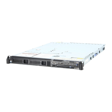
Major components of the xSeries 345 Type 8670 server..........43
Component locations.......................44
System-board option connectors .................44
PCI riser-card option connectors .................44
System-board internal cable connectors...............45
System-board external port connectors ...............45
System-board switches and jumpers ................46
System-board LED locations ...................47
Removing the cover and bezel ...................48
Working with adapters ......................48
Installing aServeRAID-5i adapter ..................54
Installing ahot-swap drive.....................55
Memory technology transition ...................56
Installing memory modules ....................57
Installing amicroprocessor ....................59
Installing ahot-swap power-supply .................66
Replacing ahot-swap fan .....................68
Replacing the battery ......................69
Completing the installation.....................71
Installing the server cover and bezel ................71
Installing the server in arack...................71
Updating your server configuration.................71
Connecting external options ...................72
Cabling the server.......................73
Input/output ports ........................73
Video port..........................74
Keyboard port ........................74
Auxiliary-device (pointing device) port ...............74
Ultra320 SCSI controller system-board connectors ...........75
Serial port..........................76
Universal Serial Bus version 1.1 ports ...............76
Ethernet ports ........................77
Integrated system-management ports ...............77
Chapter 5. Field replaceable units .................79
Hard disk drive backplane .....................79
Diagnostics/operator panel card...................80
Power-supply cage .......................81
System-board shuttle ......................82
Chapter 6. Symptom-to-FRU index .................83
Beep symptoms ........................83
No-beep symptoms .......................86
Diagnostic panel system-error LED .................86
Diagnostic error codes ......................88
Error symptoms ........................93
Power-supply LED errors..................... 101
POST error codes ....................... 102
Service processor error codes ................... 107
SCSI error codes ....................... 108
Temperature error messages ................... 108
iv xSeries 345 Type 8670: Hardware Maintenance Manual and Troubleshooting Guide
