Figures
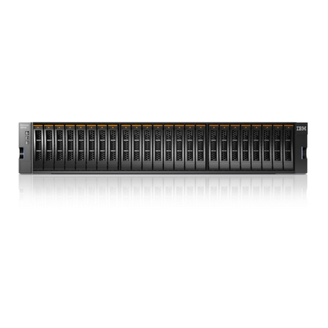
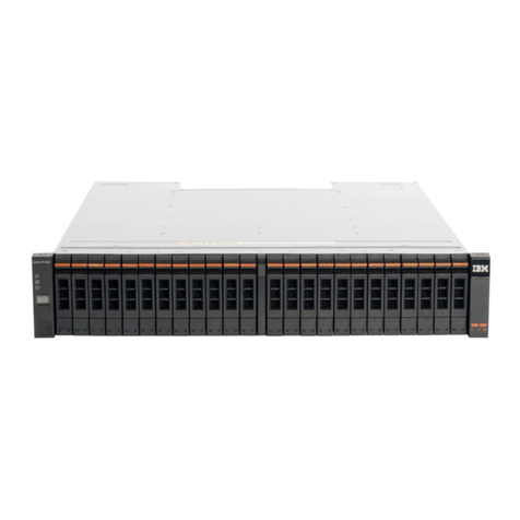
1. EXP810 hot-swap drive bays ...........................4
2. Back view; power switch, enclosure ID, and connectors .................6
3. Back view; power switch, enclosure ID, and connectors .................7
4. Rear view of drive channel ports .........................8
5. Power supply and fan unit components .......................9
6. Power supply and fan unit and airflow .......................10
7. The dc power supply and fan unit components ....................11
8. The dc power supply and fan unit and airflow ....................12
9. SFP module and fibre optic cable.........................13
10. Bezel ...................................13
11. Filter and filter retainer.............................14
12. EXP810 dimensions .............................19
13. EXP810 airflow ...............................21
14. Example of cold aisle/hot aisle rack configuration ...................25
15. Front rack mounting template ..........................33
16. Rear rack mounting template ..........................34
17. Installing the support rails ...........................36
18. Installing the EXP810 .............................37
19. Securing the storage expansion enclosure to the rack .................38
20. Installing a bezel ...............................39
21. Storage expansion enclosure seven-segment enclosure ID ...............42
22. SFP module and protective cap .........................44
23. Installing an SFP module into the host port .....................45
24. Unlocking the SFP module latch - plastic variety ...................45
25. Unlocking the SFP module latch - wire variety ....................46
26. Recommended bending and looping specifications for fibre-optic cables ..........47
27. LC-LC fibre-channel cable ...........................47
28. Removing fibre-optic cable protective caps .....................48
29. Inserting an LC-LC fibre-channel cable into an SFP module ...............49
30. LC-LC fibre-channel cable lever and latches .....................49
31. Removing the LC-LC fibre-channel cable ......................50
32. Installing an SFP module and LC-LC cable in a supported DS4000 storage subsystem .....53
33. Installing an SFP module and connecting an LC-LC cable to the EXP810 ..........53
34. Correct EXP810 redundant drive loop configuration ..................55
35. Intermixing EXP810 and EXP710 in different drive loops ................59
36. Intermixing EXP810 and EXP710 by model type behind each controller drive port .......59
37. Acceptable EXP710, EXP810 and EXP100 intermix configuration in a DS4700 or DS4800
environment ................................61
38. Cabling variations when intermixing EXP100, EXP710, and EXP810 storage expansion
enclosures behind a DS4800 Storage Subsystem ...................61
39. The dc power supply and fan unit cabling scheme - single-level redundancy .........64
40. The dc power supply and fan unit cabling scheme - dual-level redundancy .........65
41. The dc power supply connector - PIN positions....................65
42. The dc wiring from EXP810 to disconnect device and dc power source ...........66
43. The ac power supply and fan unit LEDs ......................74
44. The dc power supply and fan unit LEDs ......................74
45. Front LEDs.................................76
46. Rear LEDs, controls, and connectors .......................77
47. Numeric display LEDs.............................78
48. Cabling the EXP810 to an existing and configured drive loop ..............89
49. Removing and replacing a bezel .........................91
50. Hot-swap E-DDM LEDs ............................94
51. E-DDM CRU handle .............................95
© Copyright IBM Corp. 2006, 2009 vii
