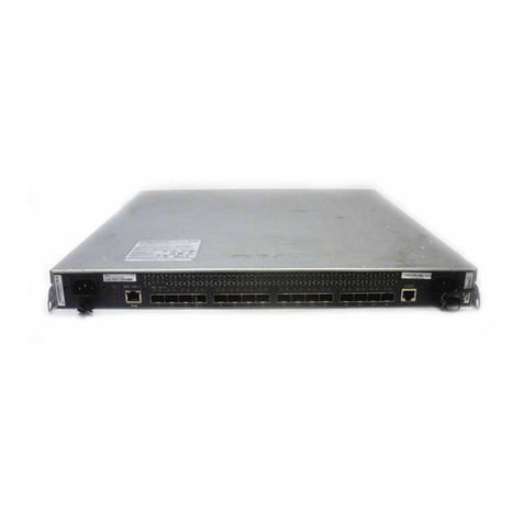
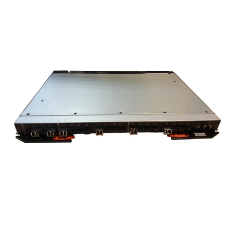
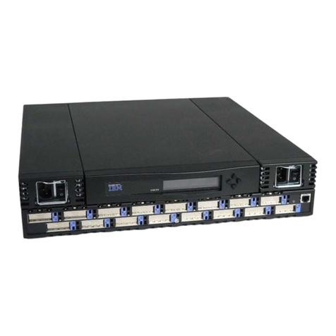
IBM 8265 Nways ATM Switch User manual

8265 Nways ATM Switch IBM
Problem Determination
and Service Guide
SY33-2128-00


8265 Nways ATM Switch IBM
Problem Determination
and Service Guide
SY33-2128-00

Note!
Before using this information and the product it supports, be sure to read the general information under “Notices”
on page xi.
First Edition (September 1998)
The information contained in this manual is subject to change from time to time. Any such changes will be reported in subsequent
revisions.
Order publications through your IBM representative or the IBM branch office serving your locality. Publications are not stocked at the
address given below.
A form for readers' comments appears at the back of this publication. If the form has been removed, address your comments to:
IBM France
Centre d'Etudes et Recherches
Service 0798 - BP 79
06610 La Gaude
France
FAX: 33 4 93 24 77 97
IBM Internal Use: LGERCF at IBMFR
Internet: [email protected]
When you send information to IBM, you grant IBM a non-exclusive right to use or distribute the information in any way it believes
appropriate without incurring any obligation to you.
Copyright International Business Machines Corporation 1998. All rights reserved.
Note to U.S. Government Users — Documentation related to restricted rights — Use, duplication or disclosure is subject to
restrictions set forth in GSA ADP Schedule Contract with IBM Corp.

Contents
Figures . . . . . . . . . . . . . . . . . . . . . . . . . . . . . . . . . . . . . . . . . vii
Tables . . . . . . . . . . . . . . . . . . . . . . . . . . . . . . . . . . . . . . . . . . . ix
Notices . . . . . . . . . . . . . . . . . . . . . . . . . . . . . . . . . . . . . . . . . . xi
Product Page/Warranties . . . . . . . . . . . . . . . . . . . . . . . . . . . . . . . . xi
European Union (EU) Statement ........................... xii
Year 2000 Statement ................................. xii
Electronic Emission Notices .............................. xiii
Trademarks and Service Marks ........................... xv
General Product and Safety Information ..................... xvii
Safety Notice for United Kingdom .......................... xvii
Service Inspection Safety Procedures ........................ xvii
Introduction . . . . . . . . . . . . . . . . . . . . . . . . . . . . . . . . . . . . . . xvii
Safety Label Locations ............................... xxi
Safety Label Identification ............................. xxii
About This Manual ................................. xxiii
Who Should Use This Manual ........................... xxiii
Purpose of This Manual ............................... xxiii
How This Manual Is Organized ........................... xxiii
Chapter 1. Start Problem Determination ..................... 1-1
Introduction . . . . . . . . . . . . . . . . . . . . . . . . . . . . . . . . . . . . . . . 1-1
Visual Symptoms . . . . . . . . . . . . . . . . . . . . . . . . . . . . . . . . . . 1-3
Other Symptoms . . . . . . . . . . . . . . . . . . . . . . . . . . . . . . . . . . 1-4
Maintenance Actions and Procedures ...................... 1-4
Module Installation . . . . . . . . . . . . . . . . . . . . . . . . . . . . . . . . . 1-5
Miscellaneous Information . . . . . . . . . . . . . . . . . . . . . . . . . . . . . 1-5
Chapter 2. MAPS . . . . . . . . . . . . . . . . . . . . . . . . . . . . . . . . . . 2-1
MAP 0100: CPSW2 and Controller Module .................. 2-2
MAP 0110: 8265 Power and Fan Control .................... 2-4
MAP 0120: CPSW2 LEDs . . . . . . . . . . . . . . . . . . . . . . . . . . . . . 2-6
MAP 0130: CPSW2/Power . . . . . . . . . . . . . . . . . . . . . . . . . . . . 2-8
MAP 0140: CPSW2/Fans . . . . . . . . . . . . . . . . . . . . . . . . . . . . 2-10
MAP 0150: CPSW2 . . . . . . . . . . . . . . . . . . . . . . . . . . . . . . . 2-12
MAP 0160: Controller Module LEDs ...................... 2-14
MAP 0170: Controller Module/Power . . . . . . . . . . . . . . . . . . . . . 2-16
MAP 0180: Controller Module/Fans . . . . . . . . . . . . . . . . . . . . . . 2-18
MAP 0190: Controller Module . . . . . . . . . . . . . . . . . . . . . . . . . 2-20
MAP 0200: Fans . . . . . . . . . . . . . . . . . . . . . . . . . . . . . . . . . 2-22
MAP 0210: CPSW/CPSW2 in Maintenance Mode .............. 2-23
MAP 0220: MNTN Code 20 ........................... 2-25
MAP 0230: MNTN Code 20 (Continued) ................... 2-26
MAP 0240: MNTN Code 20 (Continued) ................... 2-27
MAP 0250: MNTN Code 20 (Continued) ................... 2-28
MAP 0260: MNTN Code 20 (Continued) ................... 2-29
MAP 0270: MNTN Code 21 ........................... 2-30
Copyright IBM Corp. 1998 iii

MAP 0280: MNTN Code 21 (Continued) ................... 2-31
MAP 0290: MNTN Code 21 (Continued) ................... 2-32
MAP 0300: MNTN Code 22 ........................... 2-33
MAP 0310: MNTN Code 22 (Continued) ................... 2-34
MAP 0320: MNTN Code 24 ........................... 2-35
MAP 0330: MNTN Code 24 (Continued) ................... 2-36
MAP 0340: MNTN Code 25 ........................... 2-37
MAP 0350: MNTN Code 30/31 – 39/3A .................... 2-38
MAP 0360: MNTN Code 34 ........................... 2-40
MAP 0370: MNTN Code 38 ........................... 2-42
MAP 0380: MNTN Code 3A–3E/3F ...................... 2-43
MAP 0390: MNTN Code 40 ........................... 2-45
MAP 0400: Backup CPSW with No Standby LED ON ........... 2-47
MAP 0410: Arrow and Four Digits on Hexadecimal Display ........ 2-48
MAP 0420: Four Digits on Hexadecimal Display ............... 2-49
MAP 0430: Four Digits on Hexadecimal Display (Continued) ....... 2-51
MAP 0440: CPSW/CPSW2 LEDs . . . . . . . . . . . . . . . . . . . . . . . 2-52
MAP 0450: Module Installation Problem ................... 2-54
MAP 0460: Reset Problem on Media Module ................ 2-59
MAP 0470: Problem During Activity on Media Modules ........... 2-64
Compatibility Problems between Hardware and Microcode Module Levels .. 2-68
8260 Modules . . . . . . . . . . . . . . . . . . . . . . . . . . . . . . . . . . . 2-68
8265 Modules . . . . . . . . . . . . . . . . . . . . . . . . . . . . . . . . . . . 2-69
Installation of the SIMM Memory on the CPSW Module ........... 2-69
8260 Features Used in the 8265 ....................... 2-69
ESS URL . . . . . . . . . . . . . . . . . . . . . . . . . . . . . . . . . . . . . . 2-70
Chapter 3. Procedures . . . . . . . . . . . . . . . . . . . . . . . . . . . . . . . 3-1
Collecting Traces and Dumps ............................ 3-1
Trace and Dump Selection .............................. 3-1
UNI Level Problems .................................. 3-2
PNNI Level Problems ................................. 3-3
Connection Problems . . . . . . . . . . . . . . . . . . . . . . . . . . . . . . . . . 3-4
PVC Connection Problems ............................. 3-4
LAN Emulation Connection Problems ...................... 3-4
Classical IP Connection Problems ........................ 3-4
SNMP Problems . . . . . . . . . . . . . . . . . . . . . . . . . . . . . . . . . . . . 3-5
ILMI Problems . . . . . . . . . . . . . . . . . . . . . . . . . . . . . . . . . . . . . 3-6
For a Port ...................................... 3-6
For a vpc_link .................................... 3-6
Online Diagnostics . . . . . . . . . . . . . . . . . . . . . . . . . . . . . . . . . . . 3-7
Local Wrap Commands .............................. 3-7
Remote Wrap Commands ............................. 3-8
Wrap Commands Syntax .............................. 3-8
Use of commands ................................ 3-8
Completion of the command .......................... 3-9
Wraps Available . . . . . . . . . . . . . . . . . . . . . . . . . . . . . . . . . . . 3-9
How to Verify a Link ................................. 3-10
PING . . . . . . . . . . . . . . . . . . . . . . . . . . . . . . . . . . . . . . . . 3-10
ATM_PING . . . . . . . . . . . . . . . . . . . . . . . . . . . . . . . . . . . . . 3-10
Upgrading the 8265 by Code Download ...................... 3-12
In-Band Download Method ............................ 3-12
Classical IP mode ............................... 3-12
Ethernet or Token Ring LAN-Emulation Mode ............... 3-12
iv 8265 PD and SG
Serial Line Support (SLIP) Mode ....................... 3-13
8265 CPSW RJ45 Support (TCP/IP Telnet) ................ 3-13
Upgrade Synopsis . . . . . . . . . . . . . . . . . . . . . . . . . . . . . . . . . 3-14
Download Process . . . . . . . . . . . . . . . . . . . . . . . . . . . . . . . . 3-15
Summary of Important Commands and When to Use Them .......... 3-19
Maintenance Mode . . . . . . . . . . . . . . . . . . . . . . . . . . . . . . . . . . 3-23
Resetting and Changing the Password ...................... 3-24
How to Order an NVRAM .............................. 3-25
How to See the Code Level of CPSW Module .................. 3-26
How to See the Power Requirement for a Module ................ 3-27
Checking of the CPSW Module ........................... 3-28
CPSW and CPSW2 Differences .......................... 3-31
CPSW/CPSW2 - Chassis/Backplane Compatibility Table .......... 3-31
CPSW2 (FC 6502) and Controller Module (FC 8000) Coexistence .... 3-31
Chapter 4. FRU Exchange . . . . . . . . . . . . . . . . . . . . . . . . . . . . . 4-1
Exchange Precautions . . . . . . . . . . . . . . . . . . . . . . . . . . . . . . . . . 4-1
8265 FRUs and Parts Number Exchange Procedure ............... 4-1
ac Power Supply Exchange ............................ 4-2
-48 Volt dc Power Supply Exchange ....................... 4-5
Fan Unit Exchange ................................. 4-7
Controller Module Exchange ............................ 4-8
CPSW / CPSW2 Exchange ............................ 4-9
PCMCIA Exchange . . . . . . . . . . . . . . . . . . . . . . . . . . . . . . . . 4-10
DRAM SIMM Exchange ............................. 4-11
Media Module and I/O Card Exchange ..................... 4-12
EEPROM Exchange on Backplane ....................... 4-22
Chapter 5. CE Leaving Procedure ........................ 5-1
Appendix A. 8265 Part Numbers ........................ A-1
8265 Parts . . . . . . . . . . . . . . . . . . . . . . . . . . . . . . . . . . . . . . . A-1
Parts Listing . . . . . . . . . . . . . . . . . . . . . . . . . . . . . . . . . . . . A-3
Parts Listing . . . . . . . . . . . . . . . . . . . . . . . . . . . . . . . . . . . . A-5
Modules and other Part Numbers ......................... A-6
Power Cord Part Numbers ............................. A-6
Power Plug Number ............................... A-7
Bibliography . . . . . . . . . . . . . . . . . . . . . . . . . . . . . . . . . . . . . X-1
8265 Documentation . . . . . . . . . . . . . . . . . . . . . . . . . . . . . . . . . X-1
Related Documentation . . . . . . . . . . . . . . . . . . . . . . . . . . . . . . . X-1
ATM Forum . . . . . . . . . . . . . . . . . . . . . . . . . . . . . . . . . . . . . . X-1
List of Abbreviations ................................ X-3
Contents v

vi 8265 PD and SG

Figures
0-1. Ground Pin on Mainline ac Power Cable ................ xviii
0-2. Ground Pin on Mainline dc Power Cable ................. xix
0-3. Safety Label Location on 8265 ....................... xxi
0-4. Safety Label Location on dc Power Supply ............... xxi
1-1. How to identify CPSW and CPSW2 .................... 1-1
2-1. Controller Module and CPSW2 ...................... 2-2
4-1. Replacing a Defective Power Supply ................... 4-3
4-2. Power Supply Bay Grille Installation ................... 4-4
4-3. Replacing a Defective Fan Unit ...................... 4-7
4-4. Installing a Controller Module ....................... 4-8
4-5. Removing the Motherboard ........................ 4-15
4-6. Removing the Faceplate Bracket .................... 4-16
4-7. Attaching the I/O Card .......................... 4-16
4-8. Attaching the Faceplate Bracket ..................... 4-17
4-9. Reattaching the Motherboard ...................... 4-17
4-10. Removing the Motherboard ........................ 4-18
4-11. Removing the Faceplate Bracket .................... 4-19
4-12. Attaching the I/O Card .......................... 4-19
4-13. Attaching the Faceplate Bracket ..................... 4-20
4-14. Reattaching the Motherboard ...................... 4-20
4-15. EEPROM Location . . . . . . . . . . . . . . . . . . . . . . . . . . . . . 4-22
Copyright IBM Corp. 1998 vii

viii 8265 PD and SG

Tables
3-1. Wraps available on WAN Modules .................... 3-9
Copyright IBM Corp. 1998 ix

x8265 PD and SG

Notices
References in this publication to IBM products, programs, or services do not imply
that IBM intends to make these available in all countries in which IBM operates.
Any reference to an IBM product, program, or service is not intended to state or
imply that only IBM's product, program, or service may be used. Any functionally
equivalent product, program, or service that does not infringe any of IBM's
intellectual property rights may be used instead of the IBM product, program, or
service. Evaluation and verification of operation in conjunction with other products,
except those expressly designated by IBM, is the user's responsibility.
IBM may have patents or pending patent applications covering subject matter in
this document. The furnishing of this document does not give you any license to
these patents. You can send license inquiries, in writing, to the IBM Director of
Licensing, IBM Corporation, 500 Columbus Avenue, Thornwood, New York 10594,
U.S.A.
Product Page/Warranties
The following paragraph does not apply to the United Kingdom or to any
country where such provisions are inconsistent with local law.
INTERNATIONAL BUSINESS MACHINES CORPORATION PROVIDES THIS
PUBLICATION "AS IS" WITHOUT WARRANTY OF ANY KIND, EITHER EXPRESS OR
IMPLIED, INCLUDING, BUT NOT LIMITED TO, THE WARRANTIES OF
MERCHANTABILITY OR FITNESS FOR A PARTICULAR PURPOSE.
Some states do not allow disclaimer of express or implied warranties in certain
transactions, therefore this statement may not apply to you.
Copyright IBM Corp. 1998 xi

European Union (EU) Statement
This product is in conformity with the protection requirements of EU Council
Directive 89/336/EEC on the approximation of the laws of the Member States
relating to electromagnetic compatibility. IBM can not accept responsibility for any
failure to satisfy the protection requirements resulting from a non-recommended
modification of the product, including the fitting of non-IBM option cards.
Year 2000 Statement
This product is Year 2000 ready. When used in accordance with its associated
documentation, is capable of correctly processing, providing, and/or receiving date
data within and between the 20th and 21st centuries, provided all other products
(for example, software, hardware, and firmware) used with the product properly
exchange accurate date data with it.
xii 8265 PD and SG

Electronic Emission Notices
Federal Communications Commission (FCC) Statement
Note: This equipment has been tested and found to comply with the limits for a
Class A digital device, pursuant to Part 15 of the FCC Rules. These limits are
designed to provide reasonable protection against harmful interference when the
equipment is operated in a commercial environment. This equipment generates,
uses, and can radiate radio frequency energy and, if not installed and used in
accordance with the instruction manual, may cause harmful interference to radio
communications. Operation of this equipment in a residential area is likely to cause
harmful interference, in which case the user will be required to correct the
interference at his own expense.
Properly shielded and grounded cables and connectors must be used in order to
meet FCC emission limits. IBM is not responsible for any radio or television
interference caused by using other than recommended cables and connectors or by
unauthorized changes or modifications to this equipment. Unauthorized changes or
modifications could void the user's authority to operate the equipment.
This device complies with Part 15 of the FCC Rules. Operation is subject to the
following two conditions: (1) this device may not cause harmful interference, and
(2) this device must accept any interference received, including interference that
may cause undesired operation.
Notices xiii

Industry Canada Compliance Statement
This Class A digital apparatus meets all requirements of the Canadian
Interference-Causing Equipment Regulations.
Avis de conformité aux normes d'Industrie Canada
Cet appareil numérique de la classe A respecte toutes les exigences du Règlement
sur le matériel brouilleur du Canada.
Japanese Voluntary Control Council For Interference (VCCI) Statement
This equipment is in the 1st Class category (information equipment to be used in
commercial and/or industrial areas) and conforms to the standards set by the
Voluntary Control Council for Interference by Information Technology Equipment
aimed at preventing radio interference in commercial and industrial areas.
Consequently, when used in a residential area or in an adjacent area thereto, radio
interference may be caused to radios and TV receivers, and so on.
Read the instructions for correct handling.
Power Line Harmonics (JEIDA) Statement
The guidelines of power line harmonics required by JEIDA are satisfied.
Korean Communications Statement
Please note that this device has been approved for business purpose with regard to
electromagnetic interference. If you find this is not suitable for your use, you may
exchange it for a non-business one.
New Zealand Radiocommunications (Radio) Regulations
Attention: This is a Class A product. In a domestic environment this product may
cause radio interference in which case the user may be required to take adequate
measures.
Taiwanese Class A Warning Statement
This is a Class A product. In a domestic environment this product may cause radio
interference in which case the user will be required to take adequate measures.
xiv 8265 PD and SG
Trademarks and Service Marks
The following terms, denoted by an asterisk (*), used in this publication, are
trademarks or service marks of IBM Corporation in the United States or other
countries:
The following terms, denoted by a double asterisk (**), used in this publication, are
trademarks of other companies:
APPN IBM OS/2 PS/2
RETAIN XGA
Hayes Hayes Microcomputer Products, Inc.
Intel Intel Corporation
Pentium Intel Corporation
Notices xv

xvi 8265 PD and SG

General Product and Safety Information
This product meet IBM safety standards.
Safety Notice for United Kingdom
The network adapter interfaces housed within the IBM 8265 Nways ATM Switches are approved
separately, each one having its own independent approval number. These interface adapters, supplied by
IBM, do not use or contain excessive voltages. An excessive voltage is one that exceeds 42.4 V peak ac
or 60 Vdc. They interface with the IBM 8265 Nways ATM Switch using Safety Extra Low Voltages (SELV)
only. In order to maintain the separate (independent) approval of the IBM adapters, it is essential that
other optional cards, not supplied by IBM, do not use mains voltages or any other excessive voltages.
Seek advice from a competent engineer before installing other adapters not supplied by IBM.
Service Inspection Safety Procedures
Introduction
A safety inspection procedure for the 8265 should be performed:
When it is inspected for an IBM agreement
When IBM service is requested and no service has recently been performed by IBM
When an alterations and attachments review is performed
When changes have been made to the equipment that might affect its safety.
If the inspection indicates unacceptable safety conditions, the conditions must be corrected before IBM
services the machine.
Note: The correction of any unsafe condition is the responsibility of the owner of the equipment.
The 8265 areas and functions checked through these procedures are:
1. External covers
2. Safety labels
3. Safety covers and shields
4. Grounding (earthing)
5. Input power voltage
6. Power control switch
7. Power OFF
Steps 1 through 6 must be performed after power OFF as follows:
1External Covers
Check that:
They are all present on the 8265.
They are locked.
They can be fully opened.
Appropriate service clearance and access are provided around the 8265 with external covers
opened.
Leave all external covers opened to allow further safety inspection steps.
Copyright IBM Corp. 1998 xvii

2Safety Labels
Check that:
All the safety labels are at the places indicated by letters in “Safety Label Locations” on
page xxi.
Each label is of the model corresponding to the letter as shown on “Safety Label Identification”
on page xxii.
3Safety Covers and Shields
Check that all the safety covers are present and secured with screws.
4Grounding (Earthing)
aGrounding of the 8265 to the Premises Grounding System
Note
In this manual, "ground" means that the equipment must be connected to the earth.
Check that:
Electrical continuity is assured between the 8265, frame grounds, and to the premises
grounding system, through the 8265 power cords.
bac/dc Power Cable Ground Wire
Check the mainline ac/dc power cable for damaged or burned pins and broken insulation.
Measure the resistance of the disconnected mainline ac power cable from ground pin on
one end to the ground pin on the other end.
The measurement should be 0.1 ohms or less.
Ground Pin
Figure 0-1. Ground Pin on Mainline ac Power Cable
xviii 8265 PD and SG
Other manuals for 8265 Nways ATM Switch
3
Table of contents
Other IBM Switch manuals

IBM
IBM 8275 User manual

IBM
IBM 8271 User manual

IBM
IBM Nways 8271 F12 User manual

IBM
IBM 4002AC2 User manual

IBM
IBM SAN16B-2 - TotalStorage Express Model Switch Troubleshooting guide

IBM
IBM RackSwitch G8332 User manual

IBM
IBM 8265 User manual

IBM
IBM RackSwitch G8264CS User manual

IBM
IBM G8052 User manual

IBM
IBM 8239 Token-Ring Stackable Hub Safety guide