IBO 3SDm User manual

Instruction Manual of deep-well pumps of type:
3SDm, 3SD, 3ti, 3t2i, 3SKm, 4SKm, 4SCR, 4SD, 4SDm,
3.5”SCM, 3.5”SCR, 90MSC, 3”SQIBO, STING, DWP, 3”SCR, 4”ISP, 6”ISP,
4”ISPm, 4”SCR, OLA, 2,5”STm, 3STm
reading the instruction
manual is obligatory
device damage hazard
electrocution hazard
NOTE: read the manual prior to commencement of use. For safety
reasons, the pump can only be operated by persons well-familiarised.
NOTE: the manual is a primary part of the purchase and sale contract. The user’s
failure to observe the instructions included in the manual is a breach of the
contract and excludes any complaints arising from potential device failure
caused by the use that is inconsistent with instructions of its use.
NOTE: failure to observe the instructions included in the manual can
result in hazard for persons, properties in which they are installed,
environment and the pump itself.
CAUTION! This equipment is not intended for use by persons (including children) with
reduced motor, sensory or mental capacities, or persons without experience or not
familiarised with the equipment, unless it is performed under supervision
or according to the instruction regarding operation provided by persons responsible for their safety.
Attention should be paid so that children do not play with the equipment.
APPLICATION:
The pumps referred to in the manual are intended for pumping clean water from bored deep
water intakes or increasing pressure in water systems with the enclosure of the aggregate in a
hermetic jacket.
They can be used in households as water supply, means of irrigation, in heat pump
installations, and to feed water into industrial installations. The pumped water cannot contain
any mechanical contamination.
1
The pump is intended for pumping of clean water, with no solid- abrasive particles.
Pumping water containing sand results in fast wear and tear of the pump and, in
consequence, it its failure. In such a case, only paid repair is available. The above not
refers to the pumps with increased resistance to sand.

2
For these pumps the maximal sand content in water cannot exceed 5%. It must be
remembered that even the life of pumps with increased resistance against sand will be
significantly shorter when the pump will pump water with sand contamination. The wear and
tear of elements that pump sand is not subject to warranty repair. This is regarded as operating
wear and tear.
The pump is not adjusted to pump caustic, flammable, destructive or explosive substances
(e.g. petrol, nitro, oil, etc.), foodstuffs or salty water. Failure caused by pumping of the same
type of liquid is not subject to warranty repair.
The maximal temperature of the pumped water is 35oC.
The pump is not adjusted to pump water containing excessive amounts of mineral
elements causing deposition of scale on the pumping elements. The use of the pump in
such conditions results in premature wear and tear of the operating elements of the
pump. In such a case, only paid repair of the pump is available.
The pump cannot pump water containing oils and petroleum derivatives. The pump operation
in such water can lead to destruction of rubber elements, e.g. cables or sealing, and result in
leakage in the pump and motor failure. In such a case, only paid repair of the pump is
available.
Pumped water cannot contain any long-fibrous contamination.
PUMP INSTALLATION:
Prior to any installation works, power supply must be disconnected. Provide
security against accidental switch-on. Pumps 3ti, 3t2i, 3SDm, 4SD i 4SDm,
4ISP, 4ISPm, 6ISP, 3STm due to their dimensions can be delivered in two
elements. One element is a hydraulic part of the pump, the other is a motor.
Prior to connection of two elements, the clamping screws must be unscrewed
from the strip protecting the cable. Next, the screws clamping the strainer
must be unscrewed and the strainer removed. The clamping nuts with
washers must be unscrewed and removed. When the motor is placed in a
vertical position, the hydraulic element must be mounted on the motor shaft
ended with splines is placed in the clutch of the pump. If, in the course of
mounting, there are any difficulties with coupling, the motor shaft must be
turned to make the splines match the motor clutch. A hydraulic element,
correctly mounted on the motor, is fully supported by the top bearing body of
the motor. The aggregate prepared in this manner can be screwed with screw
nuts and washers. Screw nuts must be tightened crosswise. The minimal
moment of tightening screw nuts for motors 4” is 18 Nm.
If the screws are not tightened accurately, it can result in their unscrewing on operation
and motor “sinking” in the borehole. Upon installation of hydraulic element on the
motor, placing the power supply cable on the pump, the strainer must be installed and
screwed prior to the installation of the strip protecting the cable.
The lowering of the pump into the borehole without a surge protector can result in
destruction of cable isolation which can be the cause of pumpfailure or electrocution of
the operators.
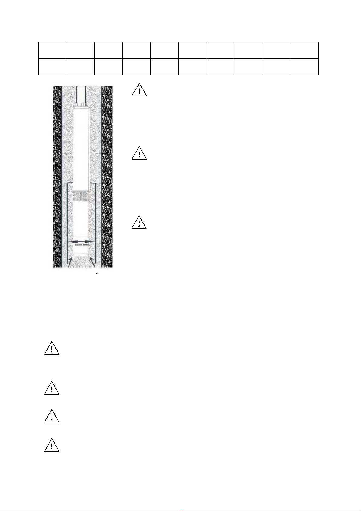
For pumps SD, SDm, SCM, ISPm, ISP, STm, due to th necessity to ensure motor
cooling on operation, the diameter of a borehole where the pump operates cannot
exceed the values presented in the table below. The values are in mm. The diameters
are consistent with the pump efficiency.

2
4
5
7
10
15
20
25
30
40
m3/h
m3/h
m3/h
m3/h
m3/h
m3/h
m3/h
m3/h
m3/h
m3/h
102
103
115
160
195
240
285
320
350
410
mm
mm
mm
mm
mm
mm
mm
mm
mm
mm
The Pump cannot operate “dry” without water. “Dry”
operation can lead to device damage. In such a case,
only paid repair is available.
In order to avoid potential dry operation, the pump must be
installed at such a depth so that the lowest, dynamic mirror level
(the mirror level set at the time of constant pumping with slow
inflow) was at least 2 m above the discharge port.
If the well efficiency disables such installation (the well is not efficient enough in relation to pump
efficiency), then you can choose one of the following solutions:
- install a valve on the pumping pipeline that will constantly limit the flow,
- install a security device protecting against dry operation, monitoring the water mirror
level which in case of dry operation hazard will switch off power supply to the
aggregate.
The use of the pump in a well with wider diameter than
shown in the table can result in motor overheating and its
failure. If the well in which the pump is to operate has
wider diameter than specified in the table, the pump must
be installed in a special jacket forcing the proper cooling.
In pic. the idea of such a jacket is presented.
The pump must be installed in the well section above the
filter. The minimal distance between the upper edge of
the top part of the well filter and the bottom edge of the
motor cannot be smaller than 30 cm. The use of the
pump installed nearer to the bottom can result in sand
suction which, in turn, can lead to faster wear and tear of
pumping elements. If the pump is placed in sludge, it can
result in motor overheating.
When lowering the pump into the well, attention must be paid that the supply cable of
the pump is fixed to the supply pipe with plastic bands in spans not exceeding 2 m.
In case of significant depth of pump installation, the cable which is not attached to the
delivery pipeline can, due to its weight, be broken.
It is also recommended that the pump is suspended on a steel line so that if the
delivery pipeline gets unscrewed, the aggregate does not sink in the well.
The check valve protecting the device against impacts of returning water must be
installed directly above the pump.
The pump motor isfilled with ecological oil. In case of motor failure, the oil can leak into
the well.
3

Prior to lowering of the pump into a new well, a user should ensure that the well
company that manufactured the well performed its purification by pumping out water.
On well construction the water inside the casing pipe and filter is contaminated with
sludge and sand.
Pumping water with sand contamination significantly shortens the life of borehole pumps.
ELECTRIC CONNECTION:
The electric network used to power the pump must be compliant with data provided on the
rating plate.
The pump must be connected to a network with active earthing.
The manufacturer and guarantor are not liable for any damage to people or property resulting
from lack of proper earthing.
The yellow-green core of the connection cable is earthing.
The powering network must be equipped with an installation, overcurrent motor circuit
breaker in e.g. M611, securing the motor against overload. In order to provide maximum
overload protection for the motor, the switch must be set to maximum coil current provided
on the rating plate.
The device can operate without this protection, but in case of a failure caused by overload,
the repair costs are incurred by the user.
The powering installation of the pump must be equipped with a residual
current device, with rated making current ΔInnot exceeding 30 mA. The
manufacturer and guarantor are not liable for any damage to people or
property resulting from supplying the pump with power without a proper
switch.
It is forbidden that there are present people or animals in the water where the
pump works.
In case of cable insulation destruction, the pump use is forbidden. In such a case, it
is necessary to contact the guarantor with the purpose of cable replacement.
Mechanical damages are not subject to warranty repairs that are free of charge.
The use of the pump with damaged cable insulation, in the best case scenario, will
lead to motor flooding with water, whereas, in the worst case scenario, it can result
in electrocution.
Prior to pump launch, the voltage at the end of the cable must be checked. It must be
remembered that the longer the cable, the lower the supply voltage at its end. Admissible
voltage drops for applied motors are ±6%.
In order to avoid excessive drop in voltage, the length of the cable must be properly selected
depending on the type of power supply (one or three-phase), motor power, cable length. The
table below facilitates the proper selection of the cable:
4
While setting the pressure switch and selecting the hydrophoric tank, the following rule
must be observed: the pump motor cannot be switched on more than 30 times an hour.
More frequent switching on can lead to motor overload and failure, or pump failure.

The maximum, acceptable cable length dependent on the
diameter of cable cores of the power supply cable
Type of
power
supply
Power of the
supplied
motor
[kW]
1
mm2
1.5
mm2
2.5
mm2
4
mm2
6
mm2
10
mm2
16
mm2
1x230 V
0.37
50
75
125
1x230 V
0.55
40
58
94
150
1x230 V
0.75
30
46
74
121
174
1x230 V
1.1
21
32
50
86
125
215
1x230 V
1.5
22
37
62
90
155
245
1x230 V
2.2
30
45
67
115
180
3x400 V
0.75
135
200
235
3x400 V
1.1
98
145
245
390
3x400 V
1.5
75
110
180
290
435
3x400 V
2.2
52
80
130
210
310
515
3x400 V
3
40
60
105
170
250
415
3x400 V
4
30
48
80
125
190
310
495
3x400 V
5.5
35
60
90
135
225
360
3x400 V
7.5
55
85
125
210
325
Not following the above instructions on cable selection can lead to pump operation
with too low voltage and consequent motor overload which can result in failure.
If the manufacturer equipped the pump with a short cable, then, it can be
extended according to the user needs. The hermetic connection of the cables
should be performed by a person with adequate knowledge and experience. The
user should assign such installation to a well fitter, or they can do it in the shop of
the well purchase. Unprofessional connection and insulation of the cables can
lead to automatic trigger of the residual-current devices, flooding motor with
water or electrocution of the user. Cable extension in types of pump equipped
with launching cable box may require its disassembly. Prior to disassembly, it is
recommended to check the connection of cable cores in the cable box and
connect the cable cores of the extension cable in the same way. Incorrect
connection can lead to motor failure, pump failure, pump operation with lowered
parameters. It is recommended that the extension of the power supply cable is
assigned to the guarantor or well fitter.
The cable box is separately delivered to some
types of pumps. There isa starting capacitor built in
the cable box as well as an overcurrent protection,
switch. The picture presents the diagram of cable
core connection of the power supply cable to the
connecting strip in the box. Cable cores of the
power supply cable aremarkedwith small tags with
core no. When identifying cores with tags or colour,
connect them according to the diagram.
5
Capacitor
(ea
rthi
ng)
Po
we
r
su
ppl
y
23
0V/
50
Hz
~1

Switch off the pump should be performed in this order:
First the pump must be disconnected, and then the aggregate can be switched off. Switching
off the aggregate with a connected pump can result in pump motor getting burnt. In such a
case, only paid repair is available.
STORAGE:
The cleaned pump must be stored in a dry room.
Attention must be paid so that the whole length of the pump is placed on an even surface.
Supporting pump in one or more points can lead to pump deflection which can result in failure.
DEVICE DISPOSAL:
the used product is subject to disposal as wastes only in selective waste
collection systems organised by the Network of Communal Electric and
Electronic Waste Collection Centres. the customer is entitled to return the used
equipment to the network of the electric equipment distributor, at least for free
and directly, if the returned device is of proper type and fulfils the same function
as a newly purchased device.
EC DECLARATION OF CONFORMITY (Module A):
PHU DAMBAT address: Gawartowa Wola 38, 05-085 KAMPINOS
Under the Act of 30 August 2002 on the conformity system (Journal of Laws of 2004, No. 204 item 2087) we
declare with full responsibility that pumps included in the series 3SDm, 3SD, 3ti, 3t2i, 3SKm, 4SKm, 4SCR,
4SD, 4SDm, 3,5”SCM, 3,5”SCR, 90MSC, 4SKt, 3SQIBO, DWP, STING, SPm, SP, 3”SCR, 4ISP,6ISP.4ISPM,
FL, OLA, STm to which this declaration refers to are consistent with the following guidelines of the Council
on legal regulations unification in member states of EC:
1) MD 2006/42/EC (applied standards EN 292-1:1991, EN 292-2-1991/A1: 1995, PN-
EN 809:1999/AC: 2004)
2) EMC 2004/108/EC (applied standards PN-EN 55014-1:2004, PN-EN 61000-3-2:2004)
3) LVD 2014/35/EU (applied standards, PN EN 60335-1:2012, PN EN 60335-2-41:2012)
Adam Jastrzębski
02.10.2017
POSSIBLE OPERATION PROBLEMS AND TROUBLESHOOTING
Sign:
Possible cause:
Problem solution:
The pump does not
operate
Security device protecting
against dry operation
triggered
Wait until the water amount in the well is sufficient for
automatic pump launch.
Overcurrent security device
triggered
Check if there is an overload. Remove the cause. Wait until
the motor cools down and switch on the pump by means of
the switch built in the protecting cable box.
6
PUMP MATCHING WITH POWER GENERATOR:
The power of the rated current of the power generator, due to its high starting
current, should be 3 to 5 times higher than the rated current power of the supplied
motor.
On pump launch the following rule must be observed: the pump can only be
connected upon the power generator launch. If the aggregate is switched on with a
connected pump, it can lead to burning of the pump motor. in such a case, only
paid repair is available.

No power supply
Check if the electric plug of the pump is properly inserted into
the electric socket.
Check fuses at home and all other types of installation fuses that
can cut off the power supply from the network
Check if there is a power supply in your neighbourhood - power
can be cut off by the power plant in the larger area
Incorrect voltage or its drop
on launch
Check the voltage Check if the cable cross-section is sufficient.
Pump operates but does
not feed water or feeds
too little
Blocked strained at suction
Disconnect the pump from power supply. Upon pump removal
from the well clean the filter
Incorrect direction of motor
rotation
Change two core cables of power supply cable in the supply strip
(only in case of three-phase motors).
Incorrect connection of core cables in the cable box (only if they
were disconnected by the user). Connect them in a correct
manner. Assign the correct connection to the service.
Too high resistance at flow
through the pumping
pipeline (hose).
Check if the maximal value of lifting for the said pump type was
not exceeded. The difference between the level of the water
mirror in the well from which the water is pumped, the level onto
which the water is pumped, the length of the pumping pipeline
(hose) and its diameter are factors which influence the height of
lifting that must be performed by the pump. If the resistance is
too high for the said pump type, replace the pump with another
one with greater lifting height.
Sand in the pump (water
with sand contamination)
Remove sand from the pump Clean the well. The pump is
installed to close to the well bottom. Pump sucks in sand.
Too low supply voltage
Check the supply voltage
Not enough water in the well
Check the pump position. The discahrge port should be placed at
least 2 m above the lowest dynamic water mirror level.
Water contamination with
sand
Worn and torn subassemblies pump water. The pump is installed
to close to the well bottom. Pump sucks in sand. Assign paid
replacement of worn and torn elements to the guarantee service.
Frequent switching on
and switching off the
pump Frequent
switching on and
switching off the pump
Hydrophoric tank is too
small
Replace the tank with a bigger one
There is no air cushion in the
tank
Check air pressure in the tank Pump in more. If the situation
often repeats, check if the tank membrane is not broken
The difference between the
switch-on and switch-off
pressure on the pressure
switch is too small
Readjust the switch
Suspended check valve
Remove the pump, replace the valve.
7

This manual suits for next models
22
Table of contents
Other IBO Water Pump manuals
Popular Water Pump manuals by other brands

Richter
Richter MNK Series Installation and operating manual

Pentair
Pentair Myers SRM4 Series Installation and operation manual

Allweiler
Allweiler NT Series Original operating manual

Sundyne
Sundyne Sunflo P-3000 Series instruction & operation manual

Meganex
Meganex MEG36300 instruction manual

Samoa
Samoa 560 230 Technical service guide

Grundfos
Grundfos MG instructions

Trebor
Trebor MAGNUM 610R Operation & maintenance manual

Sears
Sears 390.269150 owner's manual

Edwards
Edwards nEXT 55 instruction manual

Aero Mist
Aero Mist 60100K installation instructions

ALPHA DYNAMIC PUMPS
ALPHA DYNAMIC PUMPS Ruby Black Line 010 Non Metallic Installation, operation and maintenance manual