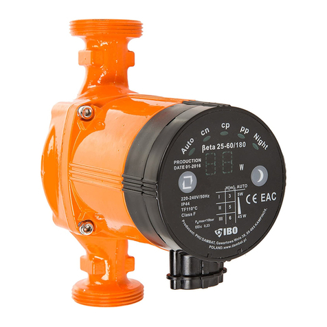
IBO BETA 25-60 User manual

1
Electronic circulator pump operating manual:
BETA 25-60
CAUTION Prior to operation, please read this operating
manual. Due to safety reasons, the use of this equipment
requires a thorough knowledge of this operating manual.
CAUTION This operating manual is the primary basis for the
equipment’s sale contract. Non-observance of the recommendations
listed in this manual will result in a breach of this contract and will
invalidate any claims made by the user relating to the equipment’s failure
resulting from its inappropriate use.
CAUTION Non-observance of recommendations listed in this
operating manual may result in personal injuries or damage to
units where the equipment is installed, the environment or the
pump itself.
CAUTION! Children and persons with reduced physical,
sensory or mental capabilities must not use this equipment;
also persons with no experience or knowledge of the product
unless under the supervision or in accordance with the equipment’s
operating manual and instructed by a person responsible for their safety.
Children must not play with this equipment.

2
APPLICATION:
The pumps which this operating manual applies to are used to enforce
circulation in central heating installations with constant or variable flows, where
the heating medium temperature does not exceed 110
o
C and the installation
pressure does not exceed 1Mpa (1 000 000Pa). The maximum ambient
temperature in the pump installation area must not exceed 40
O
C and the relative
humidity must be less than 90%.
The pumped water must not contain mechanical impurities.
The pump is designed to pump water which does not contain solids or abrasive
particles. Pumping water with mechanical impurities will shorten the pump’s
service life and may lead to its failure. This type of equipment damage is not
covered by the warranty and any repairs will have to be paid for.
The pump is not designed to pump substances which are corrosive, flammable
or have damaging or explosive properties (for example petrol, nitro, petroleum,
etc.), as well as foodstuffs and salt water. Equipment failures caused by this type
of damage are not covered by the product’s warranty.
The maximum temperature of pumped water is 110
o
C.
The pump is not adapted to pump water with an excessive level of mineral
particles, as this causes lime scale to build up on the pumping elements. Such
operating conditions will shorten the pump’s service life. This type of equipment
damage is not covered by the warranty and any repairs will have to be paid for.
The pump must not pump water which contains oils and petroleum derivatives.
If the pump operates in such conditions, it may lead to the damage of rubber
elements such as cables or seals, and as a result the pump may become unsealed
and the motor may become damaged. This type of equipment damage is not
covered by the warranty and any repairs will have to be paid for.

3
INSTALLATION:
Prior to any installation works, the power supply must always be disconnected.
It also must be secured to prevent accidental reconnections.
The pump can be connected after all the installation works are carried out on the
pipework which will form a part of the installation with the pump. It must be
remembered that welding or soldering works can introduce mechanical
impurities into the pipework. The pipework should be flushed through, prior to
the installation of the pump.
The pump should be installed with its shaft in a horizontal position. The pump’s
ports can be in different positions to the ones shown in the picture below,
however, the shaft of the pump must always be in a horizontal position.
If the pump is installed with its shaft in a vertical position, the bearings may
become quickly damaged and the pump may fail. This type of equipment
damage is not covered by the warranty and any repairs will have to be paid for.

4
The arrow moulded on the body shows the direction of water flow.
The pump should be installed in such a way that the junction box with the
control box is at the top, on the body of the motor. This will prevent water from
getting inside the junction box if the installation is not leaktight. This type of
equipment damage is not covered by the warranty and any repairs will have to
be paid for.
Although the pump can circulate water vertically down, the pump’s
manufacturer recommends that the pump circulates water vertically up or
horizontally.
ELECTRICAL CONNECTION:
The pump’s power supply network should satisfy the requirements listed on the
rating plate. The pump has a cable with a plug which can be inserted into an
earthed socket.
The pump needs to be connected to a network with an active earthing
system. The manufacturer and the guarantor will bear no responsibility for
injuries to people or any damage caused by the lack of an appropriate earthing
system.
The electrical installation which supplies power to the pump should be
equipped with an earth fault breaker for rated current which does not exceed
30 mA. The manufacturer and the guarantor will bear no responsibility for
injuries to people or any damage caused by the pump’s power supply failure due
to the lack of an appropriate breaker.

5
PUMP OPERATION CONTROL:
On the pump start-up, the electricity consumption meter’s display will display
the current power consumption level of the pump. If two horizontal bars „- - „
are displayed, it will signify that the pump is blocked. The pump should be
disconnected from the electrical network, it should be unblocked (failure
repaired) and switched on again. Switching it off and then switching it back on
again will reset the error message.
OPERATING MODE:
The subsequent pressing of the operating mode switch allows the user to select
one of the eight settings. The selected setting will be displayed by the operating
mode display.
The pump’s operating parameters are shown in the picture below, according to
chosen operating modes:

6
RECOMMENDED SETTINGS FOR DIFFERENT CENTRAL HEATING
SYSTEMS:
1) If a house has a two-pipe
heating system, where
one pipe is a supply pipe
to all the radiators in a
loop and the second
parallel pipe is used to
receive the cooled water
from the radiators, the most economic solution is to select the AUTO function.
This type of installation also permits the selection of a higher setting from PP
1
alternating pressure.
2)
If a house has a one-pipe
heating system, where
the cooled water from a
radiator enters a pipe
supplying hot water to
the next radiator and

7
only after passing through all the radiators in a loop it is taken to the boiler, the
most economic setting is the lower setting from PP
2
proportional-pressure curve.
Optionally, a higher setting from PP
1
proportional-pressure curve can also be
selected.
3) The optimum choice for under floor heating is AUTO or optionally a higher
CP
1
or a lower CP
2
constant-pressure curve setting.
NIGHT MODE:
The night mode operating setting can only be used in the following instances:
- The central heating installation and the boiler must be equipped with an
automatic regulator of the heating medium temperature which must
operate in night mode.
- The pump must be installed on the pipe coming out of the boiler. The
night mode does not work when the pump is installed on the return pipe.
- Central heating installations with a small volume of the heating medium
cannot work with a pump operating in night mode.
NIGHT MODE operating principles:
The selection of the night mode will set the pump to detect temperature changes
of the flowing water. If the temperature sensor detects a decrease in temperature
by at least 0.1
O
C/min during a period of approx. 2 hours, the pump will
automatically start operating in night mode. If the temperature of the heating
medium increases by approx. 10
O
C, the pump will automatically return to the
standard operating mode.
The night mode setting will not work if the pump is running in one of its
constant speeds. Disconnecting the electricity supply will deactivate the night
mode. Once the power supply is reconnected, the night mode needs to be
switched on again, using the appropriate switch.
START-UP, OPERATION:
Once the installation is filled up with water, the pump can be started-up.
CAUTION The installation needs to be leaktight as the pump must not be
exposed to leaking pipework. If water enters the internal elements of the pump,
the equipment will become damaged. This type of equipment damage is not
covered by the warranty and any repairs will have to be paid for. On the first
start-up, the pump should be vented using a metal plug located centrally on the
rating plate. The venting process is carried out with the pump running at a
constant speed with the plug removed, for a short period of time. A vented pump
is characterised by a lower noise level generated by the motor.
CAUTION The pump must not be used to purge the central heating
system of air! The vent valve installed above the pump should be used
for this purpose.

8
For the pump to operate correctly, there must be a minimum inlet
pressure of the heating medium (water) on the suction side of the pump.
The minimum inlet pressure of the medium is dependent on the temperature of
the medium. The higher the temperature, the higher the inlet pressure of the
heating medium on the suction side of the pump should be.
The following limits must be observed:
Heating medium
temperature [
O
C] Minimum inlet pressure on the
suction side [bar] / [m] / [Pa]
≤75 0.05 bar / 0.5 m / 5 000 Pa
90 0.28 bar / 2.8 m / 28 000 Pa
110 1.08 bar / 10.8 m / 108 000 Pa
An incorrect ratio of the ambient temperature to the heating medium
temperature may result in water vapour condensation in the terminal box
and in the motor stator. To prevent this from happening, the heating medium
temperature must be higher than the ambient temperature. The minimum
temperature of the heating medium is 2
O
C.
With the ambient temperature of 30
O
C, the maximum temperature of the
heating medium is 110
O
C. With the ambient temperature of 40
O
C, the maximum
temperature of the heating medium is 70
O
C. With the ambient temperature of
35
O
C,
the maximum temperature of the heating medium is 90
O
C.
Any equipment damage caused by water vapour condensation is not covered by
a warranty.
The surface temperature of the pump must not exceed 120
O
C.
Any equipment damage caused by the installation overheating is not
covered by the warranty.
STORAGE AND TRANSPORT:
The pump must be stored in a dry area and protected from damp. During
transport, the pump should be protected from damp and mechanical damage.
DISPOSAL OF THE PUMP:
Waste equipment must be disposed of as waste collected selectively
by the Municipal Network of Electrical and Electronic Waste
Collection Points. The consumer is entitled to return waste equipment
to the equipment distributor, free of charge and directly, if the
returned items are of the correct type and have the same function as the newly
purchased products. It is prohibited to dispose of waste electric equipment
together with other house municipal waste.

9
FAULT IDENTIFICATION AND RECOMMENDED SOLUTIONS:
Fault: Possible cause: Remedy:
Check if the pump’s electrical plug is
correctly inserted into the socket.
Check fuses at home and any other
installation fuses which could have
disconnected the power supply from the
supply network.
Electricity supply failure
Check the electrical power supply in the
vicinity of your home- the electrical current
might have been disconnected by your
energy company for the whole area.
The pump does not
run. The panel does
not display any
information.
The pump is damaged. Contact the technical maintenance
department.
The parameters of the electrical supply
current are inadequate. Check the parameters of the electrical
supply. If they are not adequate, contact the
relevant energy supplier.
The pump does not
run. The display
shows „- -„.
The bearings or the impeller are blocked
with impurities. After disconnecting the power supply from
the pump, remove it from the installation
and remove any impurities.
There is air in the pump. Remove air from the system and vent the
pump.
Increase inlet pressure by adding the
heating medium to the installation.
The inlet pressure is too low.
Check the air quantity in the expansion
vessel.
The pump is noisy;
there is noise in the
installation. The panel
displays a number.
The pump performance is too high. Decrease the pressure on the suction side.
The pump is running
but provides
insufficient heat. The
panel displays a
number.
The pump operating parameters are too
low. Increase the pressure on the suction side.
Run the pump in a higher operating mode.
CE DECLARATION OF CONFORMITY (Module A):
PHU DAMBAT
Gawartowa Wola 38, 05-085 KAMPINOS
Pursuant to the Conformity Assessment System Act of 30 August 2002 (Journal of Laws, Dz. U. from
2004, No. 204, item 2087) we declare under our sole responsibility that the series BETA pumps, to
which declaration relates, are in conformity with these following directives of the European Parliament
and the European Council, which apply to:
1) machines no. 98/37/EC (standards used PN-EN292-1:1991, PN-EN292-2-1991/A1:1995, PN-EN
809:1999/AC:2004)
2) electromagnetic compatibility no. 89/336/EEC (standards used PN-EN 55014-1:2004,
PN-EN 61000-3-2:2004)
3) electrical equipment designed to be used for selected voltage limits no. 73/23/EWG (used
standards PN-EN 60335-1:2004+ A1:2005+ A2:2008+ A12:2008, PN-EN 60335-2-51:2005)
Adam Jastrzębski
23.05.2010
Table of contents
Other IBO Water Pump manuals
Popular Water Pump manuals by other brands

Oase
Oase Neptun 1600 Warranty, safety and operating instructions

evenes
evenes HE-HL Series manual

ProMinent
ProMinent gamma XL operating instructions

NEPTUN classic
NEPTUN classic NCGP-E 70 Original operating instructions

Oase
Oase ProMax Garden Automatic 3500 operating instructions
Theralux
Theralux Theraflo TVS 1hp instruction manual