IBO BETA User manual

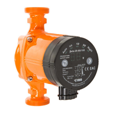
Instruction manual for electronic circulation pump:
BETA
reading the instruction
manual is obligatory
device damage hazard
electrocution hazard
NOTE: read the manual prior to commencement of use.
For safety reasons, the pump can only be operated by
persons well-familiarised with the manual.
NOTE: the manual is a primary part of the purchase and sale contract.
The user’s failure to observe
the instructions included in the manual is a breach of the contract and excludes
any complaints arising from potential device failure caused by the use that is
inconsistent with instructions of its use.
NOTE: failure to observe the instructions included in the
manual can result in hazard for persons, properties in which
they are installed, environment and the pump itself.
CAUTION! This equipment is not intended for use by persons
(including children) with reduced motor, sensory or mental
capacities, or persons
without experience or not familiarised with the equipment, unless it is
performed under supervision or according to the instruction regarding
operation provided by persons responsible for their safety.
Attention should be paid so that children do not play with the equipment.

APPLICATION:
Pumps described in this manual are intended for forcing circulation in central
heating installations with constant or variable flow in which the temperature of
heating medium does not exceed 110 oC, and pressure in the installation does not
exceed 1 Mpa (1,000,000 Pa). The maximum temperature of the surroundings
where the pump will be installed cannot exceed 40 oC, and relative moisture at the
installation site must be lower than 90%.
PUMP INSTALLATION:
Prior to any installation works, power supply must be
disconnected. Provide security against accidental switch-on.
The pump can be connected upon completion of all installation works in the
pipeline where it will operate. One should remember that, as a result of
welding or soldering works, mechanical contamination can be accumulated
in
2
The pumped water cannot contain any mechanical contamination. The
pump is intended for pumping of clean water, with no
solid or abrasive particles. Pumping water containing mechanical contamination
results in fast wear and tear of the pump and, in consequence, it its failure. In such
a case, only paid repair is available.
The pump is not adjusted to pump caustic, flammable, destructive or explosive
substances
(e.g. petrol, nitro, oil, etc.), foodstuffs or salty water. Failure caused by pumping of the
same type of liquid is not subject to warranty repair.
The maximal temperature of the pumped water is 110 oC.
The pump is not adjusted to pump water containing excessive amounts of
mineral elements causing deposition of scale on the pumping elements. Using
the pump in such conditions results in premature wear and tear of the operating
elements of the pump. In such a case, only paid repair of the pump is available.
The pump cannot pump water containing oils and petroleum derivatives.
Pump operation in such water can lead to destruction of rubber elements,
e.g. cables or sealing, and result in leakage in the pump and motor failure. In
such a case, only paid repair of the pump is available.

in the pipeline. It is recommended to flush the pipeline in which the pump is
installed prior to installation.
The pump must be
installed in such a manner
that its shaft is in a
horizontal position. Ports
can be in a different
position than shown in
this picture, however, the
motor shaft must always
be in a horizontal position.
Installation of the pump in a manner where the shaft is in vertical position results
in fast wear and tear of the bearings and failure of the pump. In such a case, only
paid repair is available.
The arrow cast on the corpus indicates the direction of water flow.
The pump should be installed in such a manner which allows for cable inlet
in the control panel box was placed in the bottom. This type of installation protects
against water penetration into the cable box in case of leakage in the water
installation. Device destruction caused by pouring water into the terminal box
from the outside is not subject to warranty repair.
Despite the possibility of pump operation in water pumping in a vertical downward
direction, the manufacturer recommends the installation which makes it pump
water vertically upward or horizontally.
ELECTRIC CONNECTION:
The electric network used to power the pump must be compliant with data
provided on the rating plate. The pump is fitted with a cable with a plug intended
for its connection to the socket with earthing.
The pump must be connected to a network with active earthing.
The manufacturer and guarantor are not liable for any
damage to people or property resulting from lack of proper earthing.
3
Vertical
motor axis
WRONG !
Horizontal
motor axis
GOOD !

OPERATION MODE:
With the use of operation mode switch, the user can select one of eleven modes by
consecutive pressing. The operation modes are classified into five setpoint groups.
Selection of one group is displayed by the light of the appropriate signal lamp in
the panel of the pump. By consecutive pressing of the operation mode switch, a
user can go through all setpoints, and within them through different operation
modes. The information on current active operation mode will be displayed for a
short time on the screen of power consumption meter mode upon pressing the
operation mode switch.
Information displayed on the screen of the meter:
AU - automatic pump parameter selection according to the installation needs
(diagram - grey colour)
∩1- constant speed, the lowest first gear (diagram - black colour)
4
The powering installation of the pump must be equipped with a
residual current device, with rated making current In not exceeding 30
mA. The manufacturer and guarantor are not liable for any damage to
people or property resulting from supplying the pump with power
without a proper switch.
PUMP OPERATION CONTROL:
Upon launch of the pump the display of the power consumption meter will show
the current power consumption of the pump. When the message “--” (two
horizontal lines) is displayed, it means that the pump is blocked. In this case the
pump must be disconnected from the electrical grid, unblocked (failure must be
eliminated) and turned on again. Turing off and again on resets the failure
message.
Operation mode signalling
unit according to fixed
gears, 1, 2, 3
Signalling unit of
automatic mode of
parameter selection
according to installation
needs
Operation mode switch
Current consumption
meter display
Night mode switch
Night mode signalling unit
Signalling unit for operation acc. to
proportional pressure PP1 PP2, PP3
characteristics
Signalling unit
for operation acc. to constant
pressure CP1.CR2.CP3

∩2 - constant speed, medium second gear (diagram - black colour)
∩3 - constant speed, highest third gear (diagram - black colour)
C1 - operation acc. to constant pressure characteristics (diagram - red colour)
C2 - operation acc. to constant pressure characteristics (diagram - red colour)
P1 - operation acc. to proportional pressure characteristics (diagram - blue colour)
P2 - operation acc. to proportional pressure characteristics (diagram - blue colour)
Parameters of pump operation depending on the selected operation mode are
presented in the diagram (example diagram for pump BETA 25-60):
RECOMMENDED SETPOINTS DEPENDING ON THE TYPE OF CENTRAL
HEATING (CO) INSTALLATION:
1)
If there is a “two-pipe” central heating installation routed in the house, i.e. one
pipe serves as the supply
line for all heaters in the
loop, and the other, in
parallel position, is used
only for collection of
cooled water from the heaters, choosing the AUTO function is most cost efficient.
In such installation it is also possible to select higher setpoint from the
characteristics of proportional pressure PP1.
5

2)
If there is a “disposable”
CO installation in the
house, i.e. water from the
radiator is cooled down
and drained into the pipe
feeding hot water into the
next radiator, and then, upon going through all radiators in an loop, it is drained to
the boiler, the most economical setpoint is the lower setpoint from characteristics
of proportional pressure PP2. The higher setpoint can also be selected from the
characteristics of proportional pressure PP2.
3) In case of floor heating, an optimal choice is an AUTO or a potentially higher
setpoint CP1, or lower CP2 from the characteristics of constant pressure.
NIGHT MODE:
Night pump operation mode can be used only when:
-CO installation with a furnace must be equipped with automatic
temperature regulation of a heating medium - that is, it must have capacity
to work in the night mode.
-The pump must be installed on the pipe exiting the furnace. The night mode
does not operate on the entering pipe.
-CO installation with small volume of heating medium cannot cooperate
with a pump operating in a night mode.
The principle of NIGHT MODE operation:
The use of the night mode switch will cause the automatic system of the pump will
monitor the temperature changes in flowing water. If the temperature signalling
unit detects temperature lowering of at least 0.1 OC/min in the period of about 2
hours, it will result in automatic switch the pump into night operation mode. In
case of increase in temperature of the heating medium of about 10OC, the pump
will automatically switch back into standard operation mode.
Night operation mode can only be launched in the automatic mode of
parameter selection of pump operation for installation parameters - AUTO
mode.
Power cut results in deactivation of the night mode. Upon restoration of power it is
necessary to switch the night mode on by pressing the proper button.
START-UP, OPERATION:
The pump can be started after the installation is filled with water.
CAUTION Attention must be paid to installation tightness, i.e. if the pump is
not flooded with dropping or leaking water from the installation.
Pump flooding with water coming from the exterior can result in device
destruction. In such a case, only paid repair is available.
6

On first launch, the installation and pump must be carefully deaerated. When the
pump is deaerated, the level of the noise generated by the device motor drops.
Observe the following limitations:
Heating medium
temperature [OC]
Minimal inflow pressure on the
suction side [bar] / [m] / [Pa]
≤ 75
0.05 bar / 0.5 m / 5 000 Pa
90
0.28 bar / 2.8 m / 28 000 Pa
110
1.08 bar / 10.8 m / 108 000 Pa
When the surrounding temperature and heating medium temperature ratio is
incorrect, it can result in water steam condensation in the terminal box and
motor stator. In order to avoid it, it is essential to observe the following rule
at all times: the temperature of heating agent must be higher than the
temperature of surroundings. Minimal temperature of heating medium is
2OC.
The temperature of surroundings cannot exceed 30OC, and the maximum
temperature of heating medium is 110OC. When the temperature of surroundings is
40OC, the temperature of heating medium cannot exceed 70OC. For 35OC of
surroundings, the max. temp. of medium is 90OC.
Device destruction as a result of water steam condensation is not subject to
warranty repair.
The temperature of pump surface can never exceed 120OC. Device
destruction as a result of installation overheating is not subject to warranty
repair.
PUMP DISPOSAL:
The used product is subject to disposal as wastes only in selective waste
collection systems organised by the Network of Communal Electric and
Electronic Waste Collection Centres. The customer is entitled to return
the used equipment to the network of the electric equipment distributor,
at least for free and directly, if the returned device is of proper type and
fulfils the same function as a newly purchased device. It is prohibited to
dispose of electric equipment together with other household wastes.
7
Failure-free pump operation requires minimal inflow pressure of heating
medium (water) on the suction side of the pump. The minimal inflow pressure
depends on the heating medium temperature. The higher the temperature, the
higher inflow pressure must be provided on the suction side of the pump.

POSSIBLE OPERATION PROBLEMS AND
TROUBLESHOOTING
Sign:
Possible cause:
Problem solution:
The pump does not
operate. The panel does not
display anything.
No power supply. Pump damaged
Check if the electric plug of the pump is properly
inserted into the electric socket.
Check fuses at home and all other types of
installation fuses that can cut off the power supply
from the network
Check if there is a power supply in your
neighbourhood - power can be shut down by the
power enterprise in the larger area Contact service.
The pump does not
operate. The panel displays
the following message: “-
-”
Incorrect parameters of supplying power.
Check parameters of supplying power. If they are
incorrect, contact with the proper power plant
Bearing or rotor is blocked with contamination.
Upon disconnection of the pump from power and
water supply, remove the pump from the
installation. Remove contamination.
Loud pump operation,
noise in the installation
Panel displays a number
Air pockets in installation
Deaerate the system, deaerate the pump.
Suction pressure is too low
Increase suction pressure by adding more heating
medium to the installation.
Check the amount of air in the collecting container.
Pump capacity is too high
Decrease pressure on the suction side of the device
Pump is operating but
installation fails to supply
enough heat. Panel
displays a number
Too low pump operation parameters
Increase pressure on the suction side of the device
Switch the pump setpoint into a higher operation
mode.
EC DECLARATION
OF CONFORMITY (Module A):
PHU Dambat
30 August 2002 on the conformity system (Journal of Laws of 2004, No. 204, item 2087) we
declare with full responsibility that BETA pumps to which this declaration refers to are
consistent with the following guidelines of the Council on legal regulations unification in
member states of EC:
—Low Voltage Directive LVD (2006/95/EC). Applied standard: EN 60335-2- 51:2003.
—Directive EMC (2004/108/EC) Applied norms: EN 55014-1:2006 and EN 55014- 2:1997.
—Eco-design Directive (2009/125/EC) Circulation pumps:
Regulation of the Commission (EC) no. 641/2009. Applied norms: EN 16297-1:2012 and EN
16297-2:2012. Gawartowa Wola 23.08.2011
Adam Jastrzębski
The reference criterion for most energy saving circulation pumps is EEI < 0.20.
For BETA pump, the coefficient EEI< 0.23 which means that BETA pump is an energy saving
pump.
8
Table of contents
Other IBO Water Pump manuals

IBO
IBO CONIBO1 User manual

IBO
IBO BETA 2 25-40/180 User manual

IBO
IBO NOVA 25-40/180 User manual

IBO
IBO STING User manual

IBO
IBO PSI Series User manual

IBO
IBO WQ User manual

IBO
IBO OHI Single-phase pipeline Series Technical Document

IBO
IBO SWIM025 User manual

IBO
IBO E-IBO 15-14 User manual

IBO
IBO BETA 25-60 User manual
Popular Water Pump manuals by other brands

SKY KING
SKY KING 3SSH1.6/80-D36/400 user manual

Profi-pumpe
Profi-pumpe DIRT-STAR-EXTRA-SS 550-1 operating instructions

Warren rupp
Warren rupp SandPIPER EB3-M Service & operating manual

Wilo
Wilo Medana CH1-LC Installation and operating instructions

KSB
KSB Etachrom L Installation & operating manual

Xylem
Xylem Bell & Gossett 1335 Series Installation, operation and maintenance manual