Middleton, WI, USA 53562
Tel: (608) 831-1255
Fax: (608) 831-2045
Email: sales@iccdesigns.com
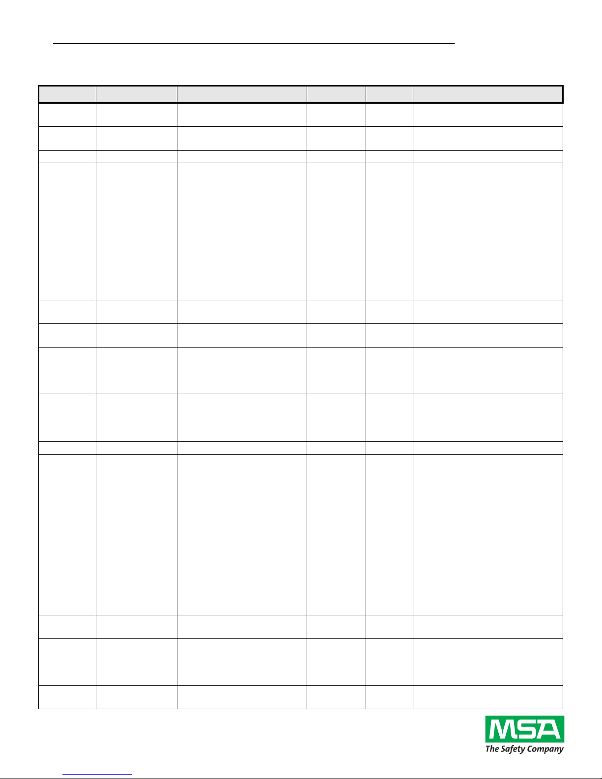
Troubleshooting
This section details some troubleshooting tips to follow if any issues are encountered when installing the gateway
and Chillgard LC onto a BACnet MS/TP network.
1. Power
a. Confirm that the gateway is receiving power from the 7 - 24V DC supply. The MS (Module Status)
LED should light green when the gateway is powered.
2. Wiring
a. Confirm the wiring matches the connections shown in Figure 2.
3. Configuration
a. Confirm that the gateway is configured with the appropriate network parameters (baud rate, MAC
address, device instance, etc) using the ICC Configuration Studio as described in the
Customizing the ETH-1000’s Configuration section.
4. Gateway LEDs
a. The MS (Module Status) LED should light green when the gateway is powered and should flash
green when the gateway is connected via USB.
i. If this is not observed, check the gateway’s power.
b. The RS-485 RX LED should flash red. The TX LED will always be off.
i. If this is not observed, check the wiring between the gateway and the Chillgard LC.
ii. Check the gateway’s configuration using the ICC Configuration Studio and confirm that
the RS-485 port is configured for Modbus Sniffer.
5. Chillgard LC Data Confirmation
a. View the gateway’s internal database via the Database pane in ICC Configuration Studio and
select the 16-bit Unsigned data type from the dropdown. There should be some highlighted cells
which do not show a value of 0.
6. BACnet Data Confirmation
a. View the gateway’s internal database via the Database pane in ICC Configuration Studio and
select the 16-bit Unsigned data type from the dropdown. The data shown in the highlighted cells
should match the data read on the BACnet system. The specific BACnet object mapped at an
address is shown when the mouse is hovered over a cell in the Database Pane.