ICC Mirius Service manual

Installation Instruction Manual
INDUSTRIAL CONTROL COMMUNICATION
100318030 2000571701 (Rev. A)
PRINTED 0419
Communication Node
for EMS/BMS
Control
Models
Ethernet (ETH-1000) for BACnet IP
and Modbus TCP
Serials
Mirius (Serial RS-485) for BACnet MS/TP)
and Modbus RTU
Energy Management System
Building Management System
Installation

2
CONTENTS
INTRODUCTION........................................................................... 3
Warnings ...................................................................................3
Parts..........................................................................................3
Tools Required ..........................................................................3
General Guidelines ...................................................................3
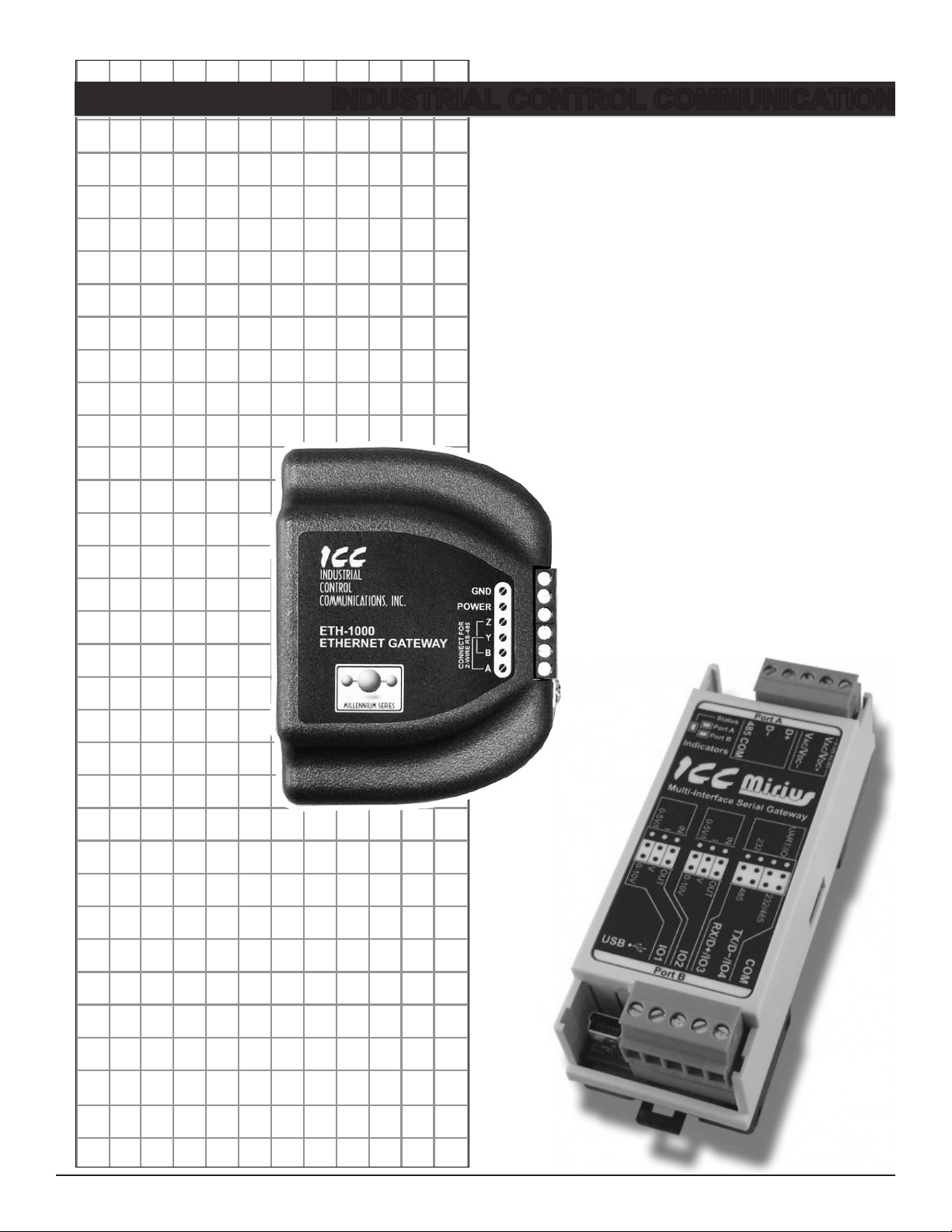
FEATURES AND COMPONENTS ................................................ 5
DEVICE CONFIGURATIONS........................................................ 6
ETH-1000 Wiring.......................................................................6
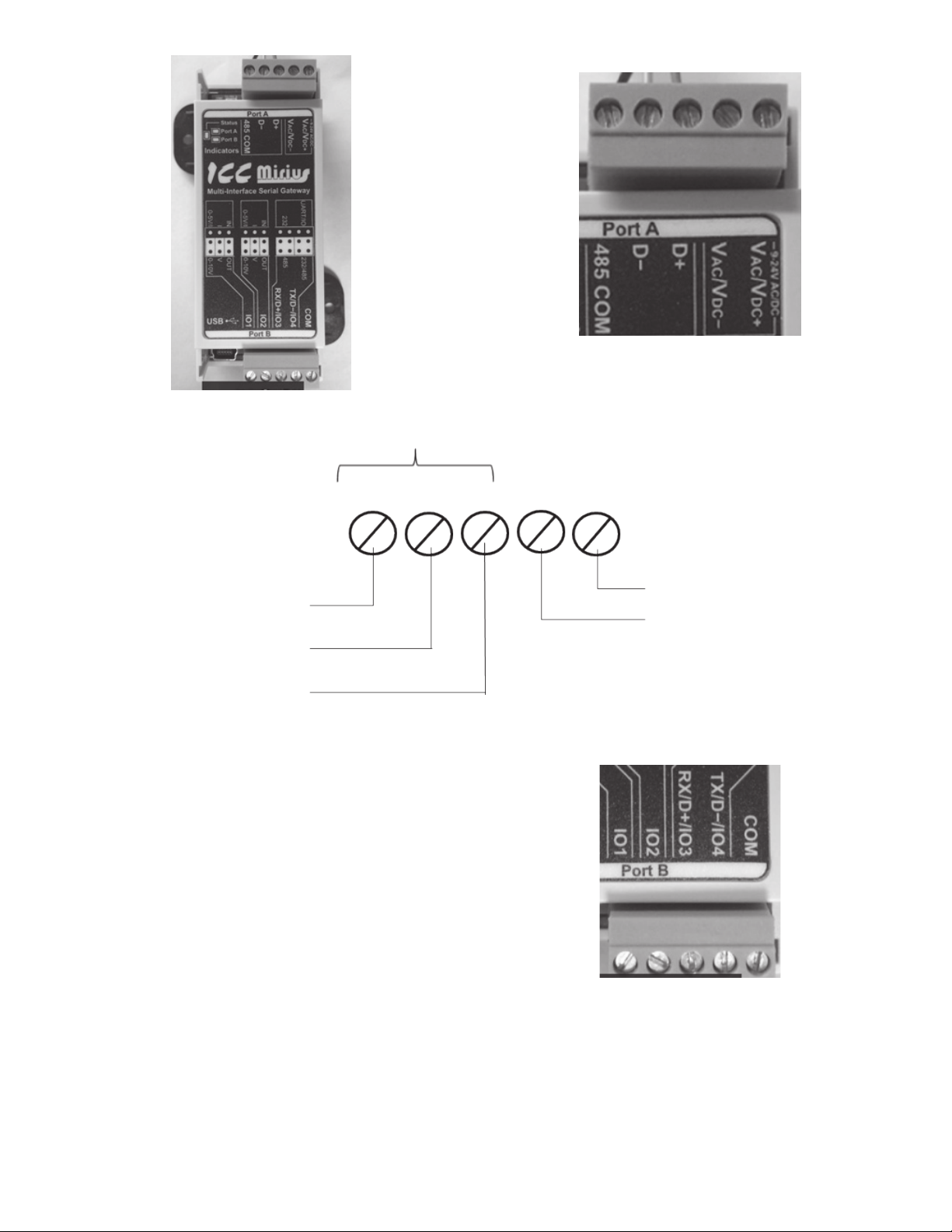
Mirius Wiring .............................................................................6
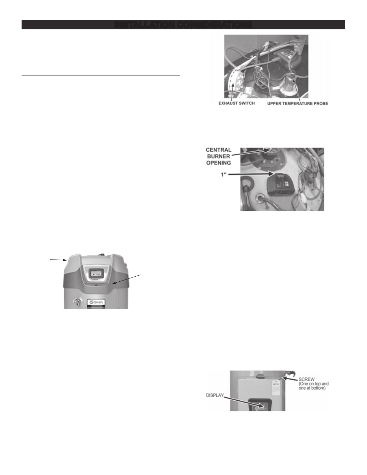
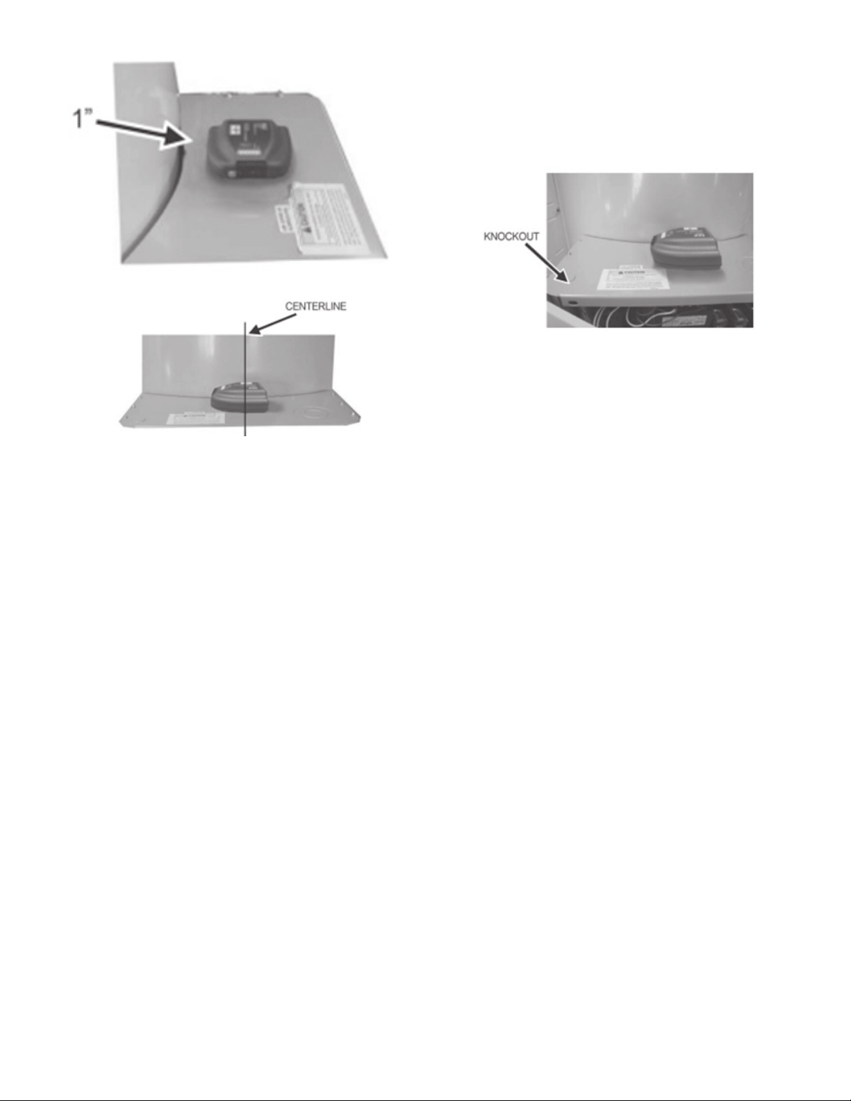
INSTALLATION CONSIDERATIONS ............................................ 8
Touch Screen Style Display Installation ....................................8
High Efciency Water Heater Installation – (BTH Or BTX
Models)................................................................................. 8
Commercial Electric Water Heater (Touch Screen
Installation) ........................................................................... 8
Membrane Switch Style Display Installation ..........................10
High Efciency Water heater Installation............................ 10
Commercial Electric Water heater Installation.................... 10
Boiler Installation.....................................................................12
XP XWH Boiler Installation................................................. 12
ECC DEVICE VERSIONS........................................................... 13
BACnet / Gas Water Heaters ..................................................13
Product Description ............................................................ 13
Protocol Implementation Conformance
Statement (PICS) ............................................................... 14
BACnet Standardized Device Prole (Annex L): .....................14
BACnet Interoperability .............................................................14
Segmentation Capability ...........................................................14
Data Link Layer Options............................................................ 14
Device Address Binding ............................................................14
Character Sets ..........................................................................15
Data Types ................................................................................15
Object Types and Properties..................................................... 16
Device Object Listings........................................................ 16
Object Min/Max Values ............................................................. 16
BACnet/Gas Water Heaters Object List .................................... 17
Central Control Board Major State Denitions .......................... 20
Xi 1.0 Energy Management System (EMS) Control..................20
Mxi Energy Management System (EMS) Control .....................21
Fault Codes and Warnings........................................................ 22
BACnet / Electric Water Heaters ............................................23
Product Description ............................................................ 23
Protocol Implementation Conformance
Statement (PICS) ............................................................... 23
BACnet Standardized Device Prole (Annex L):.......................23
BACnet Interoperability ............................................................ 23
Data Link Layer Options............................................................ 24
Device Address Binding ............................................................24
Networking Options...................................................................24
Character Sets .......................................................................... 24
Data Types ................................................................................25
Object Types and Property Support ..........................................25
Device Object Listings........................................................ 26
Device Objects Initial Values..................................................... 26
Device Objects Minimum/Maximum Values ..............................26
Central Control Board Major State Denitions .......................... 30
Energy Management System (EMS) Control ............................ 30
Fault Codes and Warnings........................................................ 30
BACnet / Boilers......................................................................32
Product Description ............................................................ 32
Protocol Implementation Conformance
Statement (PICS) ............................................................... 32
BACnet Standardized Device Prole (Annex L): ......................32
BACnet Boiler Interoperability ................................................... 32
Segmentation Capability: .......................................................... 32
Data Link Layer Options............................................................ 33
Device Address Binding ............................................................33
Character Sets .......................................................................... 33
Data Types Supported...............................................................33
Boiler Device Object Types/Property Support.......................... 34
Object Listings.................................................................... 34
Boiler Device Object Initial Values ............................................ 34
Boiler Device Object Min/Max Values .......................................35
Boiler Slave States....................................................................36
Boiler Modbus Register Access ................................................ 36
Boiler Modulating Sensor Select/DHW Demand Switch ........... 37
Lock and Hold Codes................................................................37
Modbus / Gas Water Heaters .................................................44
Product Description ............................................................ 44
Modbus Gas Water Heater Register Listings ..................... 44
Modbus Gas Water Heater Register Properties........................ 44
Central Control Board Major State Denitions .......................... 47
Xi 1.0 Energy Management System (EMS) Control..................47
Mxi Energy Management System (EMS) Control .....................47
Fault Codes and Warnings........................................................ 48
Modbus / Electric Water Heaters.............................................49
Product Description ............................................................ 49
Electric Water Heater Register Listings.............................. 49
Modbus Electric Water Heaters Register Properties................. 49
Central Control Board Major State Denitions .......................... 52
Energy Management System (EMS) Control ............................ 52
Fault Codes and Warnings........................................................ 52
ICC PROGRAM INFORMATION................................................. 53

3
INTRODUCTION
New building construction and energy saving techniques have
driven the need for improved communications between appliances
and building environmental systems. There are several different
protocols that have developed for accomplishing this task
including BACnet and Modbus. Since appliances come with a
variety of controls, interfacing with the various protocols presents
different challenges.
Industrial Control Communications (ICC) has developed the
devices to act as a communication gateway allowing appliances
to communicate to the different building management protocols.
The ICC module translates the appliance codes and commands
into the appropriate protocol language giving the end user the
ability to monitor and control the appliance. The end user will be
able to adjust and monitor the equipment and obtain better levels
of efciency and cost savings.
The ICC module in this kit has been designed to seamlessly
integrate with the water heater controls. Once the unit is
connected to the control and to the energy management system,
the user will be able to operate the unit with the Building
Management system interface.
WARNINGS
When installing the unit, ensure that all power is off before
opening any water heater enclosure. Failure to do so could result
in electrical shock and/or possible damage to the unit.
Do not install in areas of high temperature, in excess of 167° F.
Install in areas not subject to water or excess moisture.
PARTS
Table 1. Parts Required
Item Ethernet Serial (RS-485)
ICC Module X X
Communication Cable X X
Power Adapter X X
Jumpers 4 4
Splitter X X
USB Key X X
TOOLS REQUIRED
Wire Cutters
24 AWG Wire Stripper
2.5 mm Flat Blade Screw Driver
GENERAL GUIDELINES
The module should be installed as close as practical to the water
heater control.
The ICC module uses a 120 Volt power adapter to supply 9 volts
DC for the unit. One 120 VAC outlet is required for each module
installed. The power adapter comes with a six foot length of wire.
If additional wire is needed, extra wire may be added, in
accordance with local ordinances for installation of low voltage
wire.
The ICC Gateway kit contains a USB key with the ICC
Conguration Studio program, all conguration les, parameter
lists and instructions required to install and congure to your water
heater/boiler and BMS system.
Before plugging in the ICC Gateway, install the ICC Conguration
Studio from the USB key and run the program. Once running,
select File, Open Project and browse to the USB key and select
the conguration le whose name matches the gateway,
Because some USB hubs may not supply sufcient current to run
the Gateway, insure that the ICC Gateway is connected to the
power adaptor. Then connect the ICC Gateway using the USB
cable provided. Run the ICC Gateway Studio application from the
start menu.
Each conguration has default address and BACnet instance
settings that can be changed. For Mirius gateways, the default
Modbus address is 1 and the default BACnet address is 81. For
gas models the default BACnet Instance Number is 520081 and
for electric models the default instance number is 530081. For
Ethernet Gateways, the default setting is to acquire an IP address
automatically from the router (DHCP). If a static IP address is
desired this can also be set. To change these addresses and
communication settings, use the ICC Conguration Studio
application program. The latest version of this application program
can be downloaded from:
www.iccdesigns.com/icc-conguration-studio.html
Before making any changes, it is recommended to save the
installed conguration project using the disk icon or File -> Save
Project As, then give it a name and select the folder, nally press
Save.
To change the Instance number and the Device Name, scroll
down and select the Device Object and replace the text in the
boxes in the upper right corner.
Figure 1. Changing Instance Number and Device Name
For ETH-1000 (Ethernet interface) the IP settings, including
DHCP/Static, the IP address and authentication can be changed
by selecting Ethernet from the upper left hand window and
changing the text and drop down list selection similar to changing
the Instance number above.
For Mirius (RS-485 A interface for BACnet MS/TP or ModBus
RTU), the baud rate and other serial communication parameters
can be changed by scrolling down to and selecting RS-485 A ->
ModBus RTU Slave.

4
Figure 2. Changing ModBus Parameters
The ModBus address can be changed by selecting Node under
the RS-485 A -> ModBus RTU item.
Likewise for BACnet, the baud rate and other serial
communication parameters can be changed by scrolling down to
and selecting RS-485 -> BACnet MS/TP Server. The BACnet
MAC Address can be changed by selecting Node under the
RS-485 A->BACnet MS/TP Server.
Warning: Do not change any other values other than these or the
gateway conguration may not function properly. In this
case, the le saved above can be reloaded to start over.
When changes are complete press the Download Conguration icon:
Figure 3. Changing BACnet Parameters

5
FEATURES AND COMPONENTS
Figure 4. ICC ETH-1000 (Ethernet) Version Figure 5. ICC Merius Serial RS-485 Version
• Works with Cyclone (BTH, BTX-100, BTXL-100, DVE, DSE/
DVE/DHE
• Use the ICC Control to enable/disable the water heater.
• Change Temperature Set points and differentials.
• Two models with four different congurations to connect to
BACnet and Modbus.
• Ethernet and Serial RS-485 versions available.
• Two-wire or four-wire RS-485 versions available.
• Power can be supplied via the USB cable, as a 7-24 VDC
input on the main termainal block, or via IEEE 802.3af Power
over Ethernet (PoE on ETH-1000 only).
• Congure protocols, network characteristics, and client/server
object denitions.
• Graphically interact with the interal database in real-time via
the USB connection.
• Automatically discover and congure IP settings Ethernet
gateways connected to the current subnet.
• Update rmware.
Table 2. ICC Versions
Kit Connection Part Number
Mirius Serial - RS485 (RTU/MS/TP) 100316044
ETH-1000 Ethernet - RJ-45 100316045

6
DEVICE CONFIGURATIONS
ETH-1000 WIRING
Figure 6 shows the standard conguration of the Ethernet modules.
The module has connections for 9 VDC power, three wire
connections for the communication cable, and a port for the
connection of the EMS system through Ethernet RJ-45 cable or
serial communications.
Figure 6. Standard Conguration for Ethernet Modules
Connecting of the power adapter and the boiler or water heater
communication cable to the module is accomplished on the same
end of the unit. Figure 7 is a close up of the connection terminal
and Figure 8 shows the appropriate connection to the strip using
the power adapter and communication cable.
The provided communication cable has two RJ-45 plugs.
Remove one with a wire cutter, then locate and strip the 3 wires
described below and strip 1/2 inch of insulation before connecting.
Figure 7. Connecting the Power Adapter
Brown/White Wire*
Jumper
Brown Wire*
Blue/White Wire*
Black/White Wire†
Black Wire†
*From Communication Cable
†
From 9 VDC Power Adapter Cable
RS 485
AB YZ
Power
GND
Power
Pos
Jumper
Figure 8. Connections from the Communications and Power Adapter Cables
The connections in Figure 8 are the same regardless of the
appliance or the communication protocol.
At the opposite end of the module is the connection location for
the EMS LAN connection. The EMS uses an Ethernet connection
with an RJ-45 connector. Plug the cable into the RJ-45 receptacle.
When connecting the RS-485A connections, please note the
following:
For 2-wire systems, jumper terminal A to Y. Also jumper B to Z.
Connect the RX/TX+ (plus) wire from your Building Management
System to terminal A/Y. Connect the RX/TX– (minus) wire from
your Building Management System to terminal B/Z.
For more information on connecting the ICC Gateway to your
Building Management System, please refer to the User Manual
provided on the enclosed USB key in the “Documents” folder. The
two applicable documents will be found in the Manuals.
MIRIUS WIRING
Figure 9 shows the he standard conguration of the module. Port A
of the module has connections for 9 VDC power, three wire
connections for the communication (breakout) cable, for Serial
communications to the water heater/boiler.
Figure 10 is a close up of the connection terminal and Figure 11
shows the appropriate connection to the strip using the power
adapter and communication cable.

7
Figure 9. Mirius Unit with Communications Terminal
Figure 10. Close-Up View of Connection Terminal
The provided communication cable has two RJ-45 plugs.
Remove one with a wire cutter, then locate and strip the 3 wires
described below and strip 1/2 inch of insulation before connecting.
RS485
Power
GND
Power
POS
COM BA
Blue/White Wire*
Brown Wire*
Brown/White Wire*
Black/White Wire†
Black Wire†
†From 9VDC Power Adapter Cable
* From Communicaon Cable
Figure 11. Mirius Wiring Schematic
The connections in Figure 11 are the same regardless of the
appliance or the communication protocol.
At the opposite end, Port B of the module is the connection
location for the EMS/BMS connection. See Figure 12. For
connections to the terminal use the labeling on the module as a
guide.
When connecting the RS-485A connections (BACnet or Modbus)
please note the following:
• Only 2-wire systems are supported
• Connect the RX/TX+ (plus) wire from your Building
Management System to terminal RX/D+. Connect the RX/
TX– (minus) wire from your Building Management System to
terminal TX/D-. Figure 12. Mirius Port B Terminal

8
INSTALLATION CONSIDERATIONS
There are two types of displays to consider when installing the
ICC gateway modules to the water heaters, the older type with
membrane switches and the newer style with a touch screen. The
new touch screen style display does not need the provided
RJ-485 splitter and it can be discarded.
TOUCH SCREEN STYLE DISPLAY INSTALLATION
HIGH EFFICIENCY WATER HEATER INSTALLATION – (BTH OR
BTX MODELS)
Follow the directions under general guidelines for connecting the
module to the Energy Management System and power. This
section will guide the installer on how to mount and connect the
module to the water heater. The control box and mounting location
on the water heater is on the top of the unit behind the display
module. See Figure 13.
Connection of the RJ-45 end of the communication cable to the
heater is required to plug into J13 of the control board inside the
“black controls box” (for newer models) requiring removal of two
screws holding the lid on. After plugging in the communications
cable, route the cable to the bottom side with the other cables and
put the lid back on with the two screws.
If the control board is in a “grey controls box” (for older model),
double check to make sure the display is not one with membrane
switches below and to the right of the display. If the display uses
membrane switches, please follow directions under the section
“MEMBRANE SWITCH STYLE DISPLAY INSTALLATION”. If it
has a grey box and is a touch screen display (replacement of
original) then the communications cable must be plug inside the
box to J9 or J10. This will require removal of the two screws
holding the lid on. After plugging in the communications cable,
route the cable to the right side with the other cables and put the
lid back on with the two screws.
Control
Location
Top
Figure 13. Controller Location (BTH or BTX models)
Removal of the top is not required, but it may be helpful to remove
the control box lid. Use a ladder to access the top of taller water
heaters.
Next locate the upper temperature probe and exhaust switch.
Position the module between the two about 1 inch from the central
burner opening. For the 500 MBTUH Model this would be next to
the upper temperature probe.
Figure 14. Location of Exhaust Switch and Upper Temperature Probe
Connect the three wires from the end of the communication cable
to the module in Accordance with page 4. Once the unit is
installed and connected, the building management system can be
connected to the appropriate connection point on the module.
Figure 15. Clearance of ICC Unit from Central Burner Opening
COMMERCIAL ELECTRIC WATER HEATER (TOUCH SCREEN
INSTALLATION)
Normally the commercial electric heaters have a display with
membrane switches, but may have had a replacement touch
screen or future models may one day include touch screens. If
this heater has membrane switches on the bottom and right of the
display, then see the section below COMMERCIAL ELECTRIC
WATER HEATER INSTALLATION.
Follow directions under general guidance for connecting module
to the Energy Management System and power. This section will
guide the installer on how to mount and connect the module to the
water heater.
The module should be located where it will not interfere with the
door or in a location that is acceptable to the customer. Care
should be exercised to avoid drilling the self-tapping screws into
electrical or sensitive components. Electrical power should be
disconnected before proceeding with ICC installation.
Using a flat blade screwdriver, loosen the screws holding the door
of the unit. See Figure B1. Swing the door to the open position
and locate the control board.
Figure 16. Opening the Control Board Compartment Door
Locate the module on the top of the door cabinet approximately 1
inch from the water heater jacket and on the centerline of the unit
(See Figure 17 and Figure 18).

9
Figure 17. ICC Location Relative to Water Heater Jacket
Figure 18. ICC Location Relative to Centerline
Remove the hole plug from the 0.875” knockout on the left corner
of the top panel. See Figure 19.
Plug the communications cable into D9 and run the three wire
connection up through the knockout and connect the three wires
to the module as shown on page 4. Once the unit is installed and
connected, the building management system can be connected to
the appropriate connection point on the module.
Figure 19. Location of Communications Wiring Knockout

10
MEMBRANE SWITCH STYLE DISPLAY INSTALLATION
HIGH EFFICIENCY WATER HEATER INSTALLATION
Follow the directions under general guidelines for connecting the
module to the Energy Management System and power. This
section will guide the installer on how to mount and connect the
module to the water heater.
The control box and mounting location on the water heater is on
the top of the unit behind the display module. See Figure 20.
Figure 20. Locating the Control Box
Removal of the top is not required. Use a ladder to access the top
of taller water heaters. Locate the back of the display as shown in
Figure 21. Disconnect the RJ45 plug from the display and connect
the RJ45 plug from the split communication cord into the display
receptacle. Plug the display communication cord back into the
receptacle on the split communication cord as shown in Figure 22.
Plug the supplied wiring harness with the gateway controller into
the remaining open RJ45 port on the Split Communication cord.
Figure 21. Locating the Back of the Display
Figure 22. Reconnecting the Communication cord to the Receptacle
Next locate the upper temperature probe and exhaust switch. See
Figure 23. Position the module between the two about 1 inch from
the central burner opening. See Figure 24. For the 500 MBTUH
model this would be next to the upper temperature probe.
Figure 23. Locating Upper Temperature Probe and Exhaust Switch
Figure 24. Connecting the Communications Cable to the Module
Connect the three wires from the end of the communication cable
to the module in accordance with Figure 24. Once the unit is
installed and connected, the building management system can be
connected to the appropriate connection point on the module.
COMMERCIAL ELECTRIC WATER HEATER INSTALLATION
Follow directions in Device Congurations (page 6) for connecting the
module to the Energy Management System and power. This
section will guide the installer on how to mount and connect the
module to the water heater.
The module should be located where it will not interfere with the
door or in a location that is acceptable to the customer. Care
should be exercised to avoid drilling the self tapping screws into
electrical or sensitive components. Electrical power should be
disconnected before proceeding with ICC installation.
Using a flat blade screwdriver, loosen the screws holding the door
of the unit. See Figure 25.
Swing the door to the open position and locate the back of the
display module. See Figure 26.
Figure 25. Loosening the Screws to the Door of the Unit

11
Unplug the display communication cable from the display. Plug
the RJ45 plug from the split communication cable into the back of
the display. See Figure 27.
Plug the display cable into the split cable receptacle as shown in
Figure 28. Plug the supplied wiring harness with the gateway
controller into the remaining open RJ45 port on the Split
Communication cable (Not shown).
Figure 26. Locating the Communications Cable on Back of the
Display
Figure 27. Reconnecting RJ45 Plug from Split Communication Cable
Figure 28. Connecting the Display Cable to Split Cable Receptacle
Locate the module on the top of the door cabinet approximately 1
inch from the water heater jacket and on the centerline of the unit
(See Figure 29 and Figure 30).
Figure 29. Locating the Module
Figure 30. Module Location Relative to Centerline
Remove the hole plug from the 0.875” knockout on the left corner
of the top panel. See Figure 31.
Run the three wire connection from the split cable up and through
the knockout and connect the three wires to the module as shown
on page 4. Once the unit is installed and connected, the building
management system can be connected to the appropriate
connection point on the module.
Figure 31. Knockout on Left Corner of Top Panel

12
BOILER INSTALLATION
XP XWH BOILER INSTALLATION
Follow directions under general guidance for connecting module to the Energy Management System and power. This section will guide
the installer on how to mount and connect the module to the boiler.
Open the door on the low voltage wiring box on the back side of the heater to see the terminal strip where to connect the gateway to the
boiler as shown in Figure 32
Figure 32. Boiler Terminal Strip
Inside the cover of the box shows the wiring legend for the terminal strip (see Figure 33).
Figure 33. Terminal Strip Wiring Legend
Place the Gateway on top of the heater or conveniently nearby.
Locate a knock out on the right side of the low voltage box to run the communication cable through to the inside of the low voltage box.
The boiler does not have an RJ-45 connector as do the water heaters to connect Port A of the gateway, so the plug on the other end of
the communications cable must also be cut off with a wire cutter. Locate and strip the insulation ½ inch from the brown, brown/white
and blue/white wires. Connect the brown/white wire to COM2_A, the brown wire to COM2_B, and the blue/white wire to COM2_C.

13
BACnet / Gas Water Heaters
ECC DEVICE VERSIONS
Two versions of the ECC are available as follows:
Product: ICC Gateway (for use with XiTM and MXiTM Gas Water Heaters)
Product Model Number: • 100316044 (Mirius for BACnet MT/TP)
• 100316045 (ETH-1000 for BACnet IP)
Product Version: V3.000 (Mirius) or
V4.001 or greater (ETH-1000)
BACnet Protocol Revision: 12 (135-2010)
The following sections describe the ECC communications characteristics available with each of the following types of water heaters:
• BACnet/Gas
• BACnet/Electric
• BACnet/Boilers
• ModBus/Gas
• ModBus/Electric
BACNET / GAS WATER HEATERS
Figure 34. Cyclone Xi Gas Water Heaters (Virtual BACnet device via ICC Gateway)
PRODUCT DESCRIPTION
The Mirius is a multiprotocol RS-485 to RS-485 gateway. The ETH-1000 is an Ethernet to RS-485 multiprotocol gateway. These
products supports native BACnet, connecting directly to IP or the MS/TP LAN using baud rates of 4800, 9600, 19200, 38400, 57600,
76800, and 115200. As shipped the devices are congured as a BACnet Server.
All XI™ MXi™ controls provide communications via propriety protocol with the ICC Gateway. The Mirius supports BACnet MS/TP
communications and the ETH-1000 supports BACnet/IP to access data available at the display plus control of a limited number of
points such as Operating Setpoint.

14
BACnet / Gas Water Heaters
PROTOCOL IMPLEMENTATION CONFORMANCE STATEMENT (PICS)
BACnet Standardized Device Prole (Annex L):
BACnet Application Specic Controller (B-ASC)
BACnet Interoperability
Table 3. BACnet Interoperability Building Blocks Supported (Annex K):
Data Sharing - ReadProperty-A (DS-RP-A)
Data Sharing - ReadProperty-B (DS-RP-B)
Data Sharing - ReadPropertyMultiple-B (DS-RPM-B)
Data Sharing - WriteProperty-A (DS-WP-A)
Data Sharing - WriteProperty-B (DS-WP-B)
Data Sharing - WritePropertyMultiple-B (DS-WPM-B)
Data Sharing – COV-B (DS-COV-B) (BACnet/IP only)
Device Management-Dynamic Device Binding-A (DM-DDB-A)
Device Management-Dynamic Device Binding-B (DM-DDB-B)
Device Management-Dynamic Object Binding-B (DM-DOB-B)
Device Management-Device Communication Control-B (DM-DCC-B)
Device Management – ReinitializeDevice-B (DM-RD-B)
Segmentation Capability
Segmentation not supported.
Data Link Layer Options
Table 4. Data Link Layer Options
BACnet IP (Annex J) (ETH-1000 only)
BACnet IP (Annex J), Foreign Device (ETH-1000 only)
ANSI/ATA 878.1, 2.5Mb. ARCNET (Clause 8)
ANSI/ATA 878.1, RS-485. ARCNET (Clause 8), baud rates() ________
MS/TP master (Clause9) baud rate(s): 4800, 19200, 38400, 57600,
76800, 115200
MS/TP slave (Clause9) baud rate(s): _________
Point-To-Point, EIA 232 (Clause 10), baud rate(s): _________
Point-To-Point, modem (Clause 10), baud rate(s): _________
LonTalk, (Clause 11), medium ________
Other: _________________
Device Address Binding
Is static device binding supported? (This is currently for two-way communications with MS/TP slaves and certain other devices.) YES

15
BACnet / Gas Water Heaters
Networking Options
Table 5. Networking Options
Router, Clause 6 – List all routing congurations
Annex H, BACnet Tunneling Router over IP
BACnet/IP Broadcast Management Device (BBMD). Does the BBMD
support registrations by Foreign Devices? (ETH-1000 only)
Character Sets
Table 6. Character Sets Supported
ANSI X3.4
IBMTM /MicrosoftTM DBCS
ISO 8859-1
ISO 10646 (UCS-2)
ISO 10646 (UCS-4)
JIS C 6226
Data Types
The following table summarizes the data types that are accepted (in the case of a write property service) and returned (in the case of a
read property service) when targeting the present value property of each supported object type.
Table 7. Data Types Supported
Object Type
Service
Read Property Write Property
Analog Output
Analog Value
Real Real, Unsigned, Integer, Null
Analog Input Real N/A
Binary Output
Binary Value
Enumerated Enumerated, Boolean, Real, Unsigned, Integer, Null
Binary Input Enumerated N/A
Multi-state Output
Multi-state Value
Unsigned Real, Enumerated, Unsigned, Integer, Null
Multi-state Input Unsigned N/A

16
BACnet / Gas Water Heaters
Object Types and Properties
Table 8. Object Types/Property Support Table
Property Device
Binary
Input
Binary
Output
Binary
Value
Analog
Input
Analog
Output
Analog
Value
Multi
Input
Multi
Output
Multi
Value
Object Identier R R R R R R R R R R
Object Name R R R R R R R R R R
Object Type R R R R R R R R R R
System Status R
Vendor Name R
Vendor Identier R
Model Name R
Firmware Revision R
App S/W Revision R
Protocol Revision R
Services Supported R
Object Types Supported R
Object List R
Max APDU Length R
Segmentation Support R
APDU Timeout R
Number APDU Retries R
Max master R
Max Info Frames R
Device Address Binding R
Database Revision R
Present Value R W W R W W R W W
Status Flags R R R R R R R R R
Event State R R R R R R R R R
Out-of Service R R R R R R R R R
Units R R R R R R
Priority Array R R R R R
Relinquish Default R R R R R
Polarity R R
Inactive Text R R
Active Text R R
R - readable using BACnet services
W - readable and writable using BACnet services
DEVICE OBJECT LISTINGS
Object Min/Max Values
Note: Point listings have been changed completely from earlier versions of this listing.
Table 9. Device Object
Property Name ID BACnet Data Type RW Initial Value
(Mirius)
Initial Value
(ETH-1000)
Object_Identier 75 Object Identier RW Device, 520081 Device, 520081
Object_Name 77 Character String RW Water Heater-01 Water Heater-01
Object_Type 79 Enumerated R Device Device
System_Status 112 R Operational Operational

17
BACnet / Gas Water Heaters
Table 9. Device Object
Property Name ID BACnet Data Type RW Initial Value
(Mirius)
Initial Value
(ETH-1000)
Vendor_Name 121 R ICC, Inc. ICC, Inc.
Vendor_Identier 120 R 242 242
Model_Name 70 R Mirius ETH-1000
Firmware_Revision 44 Character String R V3.300 V4.002
Application_Software_Version 12 R V3.300 V4.002
Protocol_Version 98 R 1
Protocol_Revision 139 R 2
Protocol_Services_Supported 97 R See PICS
Protocol_Object_Types_Supported 96 R AI, AO, AV, BI,
BO, BV, MSI,
MSO, MSV
AI, AO, AV, BI,
BO, BV, MSI,
MSO, MSV
Object_List 76 R See Table See Table
Max_APDU_Length_Accepted 62 R 480 1444
Segmentation_Supported 107 R 3 3
APDU_Timeout 10 RW 1000ms 1000ms
Number_Of_APDU_Retries 73 R 3 3
Max_Master 64 RW 127 Unsupported
Device_Address_Binding 30 R {} {}
Local_Date 56 R Unsupported Unsupported
Local_Time 57 R Unsupported Unsupported
BACnet/Gas Water Heaters Object List
• Not all models support all registers. Also parameter names may be different than shown here on some models.
• This table may be subject to change in the future.
• Adjustable objects are in bold and indicated by “W” (writable).
Table 10. BACnet/Gas Water Heaters Object List
BACnet
Object Name
(Description)
BACnet
Object
Type/Inst.
BACnet
Object
Property R/W Units
Min
Value
(if W)
Max
Value
(if W) Xi 1.0 Mxi
Firmware Ver-Rev1
(Firmware Version)
Analog Input 1 Present_Value R
Conguration Analog Input 2 Present_Value R
Upper Temperature
(Upper or Primary Temperature)
Analog Input 3 Present_Value R ºC
Lower Temperature
(Lower or Secondary Temperature)
Analog Input 4 Present_Value R ºC
Tank Temperature
(Controlling Tank Temperature algorithmically
calculated)
Analog Input 5 Present_Value R ºC
Temper Setpoint
(Desired Tank Temperature)
Analog Value 201 Present_Value R/W ºC
(ºF)
32.2
(90)
82.2
(180)
SetPoint Differ
(Setpoint Differential)
Analog Value 202 Present_Value R/W °C
(°F)
1.1
(2)
11.1
(20)
1. Data is encoded into the 16 bits as major revision (upper 8 bits) and minor revision (lower 8 bits).
2. Not recommended for use currently as UIM does not currently support and warning will come up as “Unknown.”

18
BACnet / Gas Water Heaters
Table 10. BACnet/Gas Water Heaters Object List
BACnet
Object Name
(Description)
BACnet
Object
Type/Inst.
BACnet
Object
Property R/W Units
Min
Value
(if W)
Max
Value
(if W) Xi 1.0 Mxi
Mxi Mod% Cmd
Commands Modulation % (0%=minimum heat,
100%=rated heat). Note: It is really an upper limit.
If heater wants to command less it will.
Analog Value 207 Present_Value R/W % 0 100
MxiLowTempAlrmSP2
(Low Temperature Alarm)
Analog Value 208 Present_Value R/W ºC
(ºF)
32.2
(90)
82.2
(180)
Number of Cycles
(Number of heating cycles)
Analog Value 209 Present_Value R
Elapsed Time
(Time heater has been powered up in Hours with
two place beyond the decimal)
Analog Value 210 Present_Value R Hours with two
places beyond
the decimal.
Elapsed Days
(The number of days that the heater has been
powered up)
Analog Value 211 Present_Value R Days
Elapsed Hours
(The hours portion that the heater has been pow-
ered up. Use with Elapsed Days)
Analog Value 212 Present_Value R Hours
Heating Time
(Time heater has been actually heating water in
Hours with two place beyond the decimal)
Analog Value 213 Present_Value R Hours with two
places beyond
the decimal.
Heating Days
(The amount of time in number of days heater has
been actually heating water)
Analog Value 214 Present_Value R Days
Heating Hours
(The hours portion of the amount of time heater
has been actually heating water. Use with Heating
Days)
Analog Value 215 Present_Value R Hours
IgniterCurrent
(Hot Surface Igniter current in amps)
Analog Value 216 Present_Value R Amps
#CCB HW Faults
(CCB Hardware Fault Counter)
Analog Value 217 Present_Value R
#Model Faults
(Model Fault Counter)
Analog Value 218 Present_Value R
#Upper Temp Faults
(Upper Temperature Probe Fault Counter)
Analog Value 219 Present_Value R
#Lower Temp Faults
(Lower Temperature Probe Fault Counter)
Analog Value 220 Present_Value R
#Flame Probe Flt
(Flame Probe Fault Counter)
Analog Value 221 Present_Value R
#Flame Status Flt
(Flame detect or not detected at proper time Fault
Counter)
Analog Value 222 Present_Value R
#CCB Comm Faults
(Communication Fault Counter)
Analog Value 223 Present_Value R
#ECO Faults
(High temperature Energy Cut Off switch in Upper
temperature probe Fault Counter)
Analog Value 224 Present_Value R
#LowGasPress Flt
(Low Gas Pressure switch Fault Counter)
Analog Value 225 Present_Value R
#Blocked In Flts
(Blocked Inlet pressure switch Fault Counter)
Analog Value 226 Present_Value R
#Blocked Exhst Flt
(Blocked Exhaust Pressure & Condensate switch
Fault Counter)
Analog Value 227 Present_Value R
#Ext Vent Faults
(External Vent Fault Counter)
Analog Value 228 Present_Value R
#Blower Prv Flts
(Blower Prove Pressure Switch Fault Counter)
Analog Value 229 Present_Value R
#Igniter Faults
(Igniter Fault Counter)
Analog Value 230 Present_Value R
1. Data is encoded into the 16 bits as major revision (upper 8 bits) and minor revision (lower 8 bits).
2. Not recommended for use currently as UIM does not currently support and warning will come up as “Unknown.”

19
BACnet / Gas Water Heaters
Table 10. BACnet/Gas Water Heaters Object List
BACnet
Object Name
(Description)
BACnet
Object
Type/Inst.
BACnet
Object
Property R/W Units
Min
Value
(if W)
Max
Value
(if W) Xi 1.0 Mxi
#Ignition Failure
(Ignition Failure Fault Counter)
Analog Value 231 Present_Value R
#Powr Supply Flt
(Power Supply Fault Counter)
Analog Value 232 Present_Value R
#Powr Anode Flts
(Powered Anode Alert Counter)
Analog Value 233 Present_Value R
EMS Mode-Status Analog Value 263 Present_Value R/W Xi 1.0 see table 3
Upper Temp Open
(Upper temperature Probe open status)
Binary Input 301 Present_Value R 0 = Okay
1 = Open
Upper Temp Short
(Upper temperature Probe shorted status)
Binary Input 302 Present_Value R 0 = Okay
1 = Shorted
MXi Call For Heat Binary Input 303 Present_Value R 0 = No
1 = Yes
Lower Temp Open
(Upper temperature Probe open status)
Binary Input 304 Present_Value R 0 = Okay
1 = Open
Lower Temp Short
(Upper temperature Probe shorted status)
Binary Input 305 Present_Value R 0 = Okay
1 = Shorted
Igntr Current OK
(Igniter Current Sensed)
Binary Input 306 Present_Value R 0=No Current
1=Current
Sensed
Flame Sensed
(Igniter Current Sensed)
Binary Input 307 Present_Value R 0=No Flame
1=Flame Sensed
Blower Prove PS
(Blower Prove pressure switch)
Binary Input 308 Present_Value R 0=Open Switch
1=Closed Switch
Ext Vent PS
(External Vent pressure switch status if selected by
DIP switch on CCB)
Binary Input 309 Present_Value R 0=Open Switch
1=Closed Switch
Blocked Exhaust PS
(Blocked exhaust pressure switch)
Binary Input 310 Present_Value R 0=Open Switch
1=Closed Switch
Blocked Inlet PS
(Blocked air intake pressure switch)
Binary Input 311 Present_Value R 0=Open Switch
1=Closed Switch
Low Gas PS
(Low Gas supply pressure switch)
Binary Input 312 Present_Value 0=Open Switch
1=Closed Switch
Upper Temp ECO
(Upper temperature probe high temperature Ener-
gy Cut Out Status)
Binary Input 313 Present_Value 0=Open Switch
1=Closed Switch
External T’stat
(External Thermostat status if selected by DIP
switch on CCB)
Binary Input 314 Present_Value 0 = No
1 = Yes
Xi 1.0 Call For Heat
(Conditions are satised to allow heater to heat
water)
Binary Input 315 Present_Value 0 = Okay
1 = Alarm
MXi LowTemp Alrm
(Tank temperature below Low Tank Temperature
Alarm setpoint)
Binary Input 316 Present_Value 0 = Okay
1 = Alarm
MXi LeakDetected
(Optional Leak detector circuit detected water)
Binary Input 317 Present_Value 0=No Leak
1=Leak Detected
Mxi HeaterEnab’d
(Front Switch Heater Enable status)
Binary Input 318 Present_Value 0=Disabled
1 = Enabled
MXi External Enab
(Optional input status)
Binary Input 319 Present_Value 0=Disabled
1 = Enabled
Xi 1.0 Ign Tries
(Number of tries for ignition set by DIP switch on
CCB)
Binary Input 320 Present_Value 0 = 3 tries
1 = 1 try
Ext Vent Relay
(External Vent Relay output commanded status)
Binary Output 401 Present_Value 0 = Off
1 = On
1. Data is encoded into the 16 bits as major revision (upper 8 bits) and minor revision (lower 8 bits).
2. Not recommended for use currently as UIM does not currently support and warning will come up as “Unknown.”

20
BACnet / Gas Water Heaters
Table 10. BACnet/Gas Water Heaters Object List
BACnet
Object Name
(Description)
BACnet
Object
Type/Inst.
BACnet
Object
Property R/W Units
Min
Value
(if W)
Max
Value
(if W) Xi 1.0 Mxi
Blower Relay
(Blower Relay output commanded status)
Binary Output 402 Present_Value 0 = Off
1 = On
Ignition Relay
(Ignition Relay output commanded status)
Binary Output 403 Present_Value 0 = Off
1 = On
Gas Valve Relay
(Gas valve Relay output commanded status)
Binary Output 404 Present_Value 0 = Off
1 = On
MXi Ign Tries
(Selects 1 or 3 tries for ignition. Settable at UIM)
Binary Value 501 Present_Value 0 = 3 tries
1 = 1 try
MXi Use Ext Enab
(Selects whether or not to use Optional External
Enable Input. Settable at UIM)
Binary Value 502 Present_Value 0 = No
1 = Yes
MXi Modulation
(CCB S/W version 3.15 or higher. Disables mod-
ulation on heaters that have it. May be helpful if
plumbed with Xi 1.0. Settable at UIM)
Binary Value 503 Present_Value 0=Disabled
1=Enabled
System In Fault Binary Value 504 Present_Value 0 = Okay
1 = Alarm
System State
(CCB Control State)
Multistate Value 801 Present_Value
See Table 10
Fault Code Multistate Value 802 Present_Value See Table 13
Alert Code Multistate Value 803 Present_Value See Table 13
1. Data is encoded into the 16 bits as major revision (upper 8 bits) and minor revision (lower 8 bits).
2. Not recommended for use currently as UIM does not currently support and warning will come up as “Unknown.”
Central Control Board Major State Denitions
Table 11. Gas Central Control Board (CCB) Major State Denitions
Value Xi 1.0 State MXi State
1 Off (Standby) Off (Standby)
2 Pre-Purge Pre-Purge
3 Igniter Warmup Igniting
4Ignition Activation Gas Valve On
5Ignition Verication Inter-Purge
6 Inter-Purge Heating
7 Heating Post-Purge
8 Post-Purge In Fault
9 Fault
Xi 1.0 Energy Management System (EMS) Control
Xi 1.0 uses a single bit setting method. Within the EMS Mode-Status point one bit command (bit 15) sets it in EMS mode, and other
ends EMS mode. Once in EMS mode, another bit command (bit 0) enables heating another disables heating.
Once in EMS mode the EMS Mode Refresh command must be periodically issued which clears a third bit (bit 14) to maintain EMS
mode, otherwise the heater will end EMS mode and resume normal operation.
Other manuals for Mirius
1
This manual suits for next models
1
Table of contents
Other ICC Gateway manuals
Popular Gateway manuals by other brands

AudioCodes
AudioCodes Mediant 600 user manual

H3C
H3C SecPath M9000 Series Installation, quick start

Iseo
Iseo Zero1 user manual

Sargent and Greenleaf
Sargent and Greenleaf 6128 Programming and operations guide

Panduit
Panduit SmartZone EPA064 user manual

ZyXEL Communications
ZyXEL Communications ZyAIR G-4100 user guide

Eaton
Eaton Moeller SmartWire-Darwin EU5C-SWD-DP Instruction leaflet

Yeastar Technology
Yeastar Technology TB200 installation guide

Grace Digital
Grace Digital Xlink ITC-BT owner's manual

Epygi
Epygi QuadroFXO Administrator's guide

Eurotech
Eurotech BoltGATE 20-25 user manual

US Robotics
US Robotics USR3520 user guide