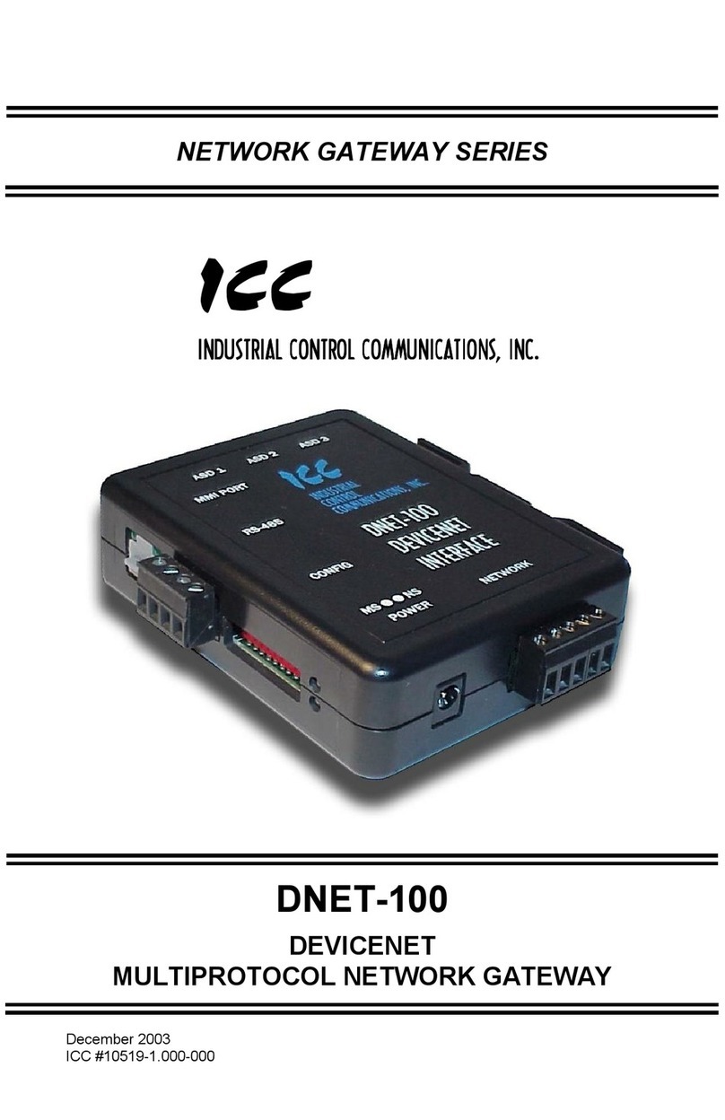
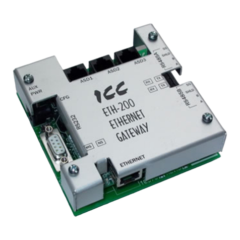
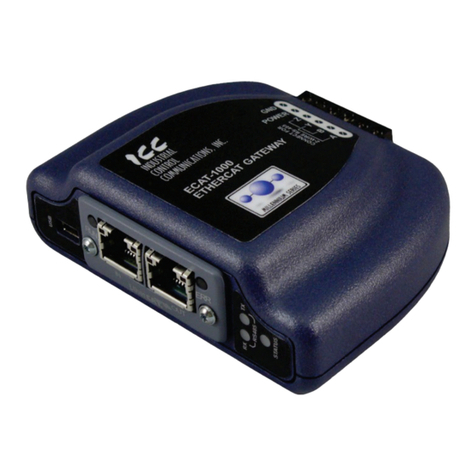
ICC ETH-1000 User manual

100334325 2000590389A
PRINTED 0620
Installation Manual
INTER-APPLIANCE COMMUNICATIONS
Models
Ethernet (ETH-1000) for BACnet IP
and Modbus TCP
Serials
Mirius (Serial RS-485) for BACnet MS/TP)
and Modbus RTU
Energy Management System
Building Management System
Installation
Communication Node
for EMS/BMS
Control

2
CONTENTS
CONTENTS
INTRODUCTION...........................................................................3
Warnings...................................................................................3
Parts..........................................................................................3
Tools Required..........................................................................3
General Guidelines ...................................................................3
FEATURES AND COMPONENTS ................................................5
DEVICE CONFIGURATIONS........................................................6
ETH-1000 Wiring.......................................................................6
Mirius Wiring .............................................................................6
INSTALLATION CONSIDERATIONS ............................................8
Touch Screen Style Display Installation....................................8
+LJK(I¿FLHQF\:DWHU+HDWHU,QVWDOODWLRQ±%7+2U%7;
Models).................................................................................8
&RPPHUFLDO(OHFWULF:DWHU+HDWHU7RXFK6FUHHQ
Installation)...........................................................................8
Membrane Switch Style Display Installation ............................9
+LJK(I¿FLHQF\:DWHUKHDWHU,QVWDOODWLRQ..............................9
Commercial Electric Water heater Installation....................10
%RLOHU,QVWDOODWLRQ.....................................................................11
;3;:+%RLOHU,QVWDOODWLRQ ................................................. 11
ECC DEVICE VERSIONS...........................................................12
%$&QHW*DV:DWHU+HDWHUV ..................................................12
Product Description............................................................12
3URWRFRO,PSOHPHQWDWLRQ&RQIRUPDQFH6WDWHPHQW3,&6.13
%$&QHW6WDQGDUGL]HG'HYLFH3UR¿OH$QQH[/.....................13
%$&QHW,QWHURSHUDELOLW\ .............................................................13
6HJPHQWDWLRQ&DSDELOLW\ ...........................................................13
'DWD/LQN/D\HU2SWLRQV............................................................13
'HYLFH$GGUHVV%LQGLQJ ............................................................13
&KDUDFWHU6HWV ..........................................................................14
'DWD7\SHV ................................................................................14
2EMHFW7\SHVDQG3URSHUWLHV.....................................................15
Device Object Listings........................................................15
2EMHFW0LQ0D[9DOXHV .............................................................15
%$&QHW*DV:DWHU+HDWHUV2EMHFW/LVW ....................................16
&HQWUDO&RQWURO%RDUG0DMRU6WDWH'H¿QLWLRQV ..........................19
;L(QHUJ\0DQDJHPHQW6\VWHP(06&RQWURO..................19
0[L(QHUJ\0DQDJHPHQW6\VWHP(06&RQWURO .....................20
)DXOW&RGHVDQG:DUQLQJV........................................................21
%$&QHW(OHFWULF:DWHU+HDWHUV............................................22
Product Description............................................................22
3URWRFRO,PSOHPHQWDWLRQ&RQIRUPDQFH6WDWHPHQW3,&6.22
%$&QHW6WDQGDUGL]HG'HYLFH3UR¿OH$QQH[/.......................22
%$&QHW,QWHURSHUDELOLW\ ............................................................22
'DWD/LQN/D\HU2SWLRQV............................................................23
'HYLFH$GGUHVV%LQGLQJ ............................................................23
1HWZRUNLQJ2SWLRQV...................................................................23
&KDUDFWHU6HWV ..........................................................................23
'DWD7\SHV ................................................................................24
2EMHFW7\SHVDQG3URSHUW\6XSSRUW ..........................................24
Device Object Listings........................................................25
'HYLFH2EMHFWV,QLWLDO9DOXHV.....................................................25
'HYLFH2EMHFWV0LQLPXP0D[LPXP9DOXHV ..............................25
&HQWUDO&RQWURO%RDUG0DMRU6WDWH'H¿QLWLRQV ..........................29
(QHUJ\0DQDJHPHQW6\VWHP(06&RQWURO ............................29
)DXOW&RGHVDQG:DUQLQJV........................................................29
%$&QHW%RLOHUV......................................................................31
Product Description............................................................31
3URWRFRO,PSOHPHQWDWLRQ&RQIRUPDQFH6WDWHPHQW3,&6.31
%$&QHW6WDQGDUGL]HG'HYLFH3UR¿OH$QQH[/......................31
%$&QHW%RLOHU,QWHURSHUDELOLW\ ...................................................31
6HJPHQWDWLRQ&DSDELOLW\ ..........................................................32
'DWD/LQN/D\HU2SWLRQV............................................................32
'HYLFH$GGUHVV%LQGLQJ ............................................................32
&KDUDFWHU6HWV ..........................................................................32
'DWD7\SHV6XSSRUWHG...............................................................32
%RLOHU'HYLFH2EMHFW7\SHV3URSHUW\6XSSRUW..........................33
Object Listings....................................................................33
%RLOHU'HYLFH2EMHFW,QLWLDO9DOXHV ............................................33
%RLOHU'HYLFH2EMHFW0LQ0D[9DOXHV .......................................34
%RLOHU6ODYH6WDWHV....................................................................35
%RLOHU0RGEXV5HJLVWHU$FFHVV ................................................35
%RLOHU0RGXODWLQJ6HQVRU6HOHFW'+:'HPDQG6ZLWFK ...........36
/RFNDQG+ROG&RGHV................................................................36
0RGEXV*DV:DWHU+HDWHUV.................................................43
Product Description............................................................43
Modbus Gas Water Heater Register Listings.....................43
0RGEXV*DV:DWHU+HDWHU5HJLVWHU3URSHUWLHV........................43
&HQWUDO&RQWURO%RDUG0DMRU6WDWH'H¿QLWLRQV ..........................46
;L(QHUJ\0DQDJHPHQW6\VWHP(06&RQWURO..................46
0[L(QHUJ\0DQDJHPHQW6\VWHP(06&RQWURO .....................46
)DXOW&RGHVDQG:DUQLQJV........................................................47
0RGEXV(OHFWULF:DWHU+HDWHUV.............................................48
Product Description............................................................48
Electric Water Heater Register Listings..............................48
0RGEXV(OHFWULF:DWHU+HDWHUV5HJLVWHU3URSHUWLHV.................48
&HQWUDO&RQWURO%RDUG0DMRU6WDWH'H¿QLWLRQV ..........................51
(QHUJ\0DQDJHPHQW6\VWHP(06&RQWURO ............................51
)DXOW&RGHVDQG:DUQLQJV........................................................51
ICC PROGRAM INFORMATION.................................................52

3
INTRODUCTION
INTRODUCTION
Newbuilding construction andenergy saving techniqueshave driven
the need for improved communications between appliances and
buildingenvironmentalsystems.There are severaldifferentprotocols
WKDWKDYHGHYHORSHGIRUDFFRPSOLVKLQJWKLVWDVNLQFOXGLQJ%$&QHW
and Modbus. Since appliances come with a variety of controls,
interfacing with the various protocols presents different challenges.
,QGXVWULDO&RQWURO&RPPXQLFDWLRQV,&&KDVGHYHORSHGWKHGHYLFHV
to act as a communication gateway allowing appliances to
communicate to the different building management protocols. The
ICC module translates the appliance codes and commands into the
appropriate protocol language giving the end user the ability to
monitorand controlthe appliance. The enduser willbe abletoadjust
DQGPRQLWRUWKHHTXLSPHQWDQGREWDLQEHWWHUOHYHOVRIHI¿FLHQF\DQG
cost savings.
TheICC module inthis kit hasbeendesigned toseamlesslyintegrate
with the water heater controls. Once the unit is connected to the
control and to the energy management system, the user will be able
WRRSHUDWHWKHXQLWZLWKWKH%XLOGLQJ0DQDJHPHQWV\VWHPLQWHUIDFH
WARNINGS
When installing the unit, ensure that all power is off before opening
anywater heaterenclosure. Failureto doso couldresult inelectrical
VKRFNDQGRUSRVVLEOHGDPDJHWRWKHXQLW
Donot installinareas ofhightemperature, inexcess of167°F. Install
in areas not subject to water or excess moisture.
PARTS
Table 1. Parts Required
Item Ethernet Serial (RS-485)
ICC Module ;;
Communication Cable ;;
Power Adapter ;;
Jumpers 4 4
Splitter ;;
86%.H\ ; ;
TOOLS REQUIRED
Wire Cutters
• 24 AWG Wire Stripper
• PP)ODW%ODGH6FUHZ'ULYHU
GENERAL GUIDELINES
The module should be installed as close as practical to the water
heater control.
The ICC module uses a 120 Volt power adapter to supply 9 volts
DC for the unit. One 120 VAC outlet is required for each module
installed. The power adapter comes with a six foot length of wire. If
additional wire is needed, extra wire may be added, in accordance
with local ordinances for installation of low voltage wire.
7KH,&&*DWHZD\NLWFRQWDLQVD86%NH\ZLWKWKH,&&&RQ¿JXUDWLRQ
6WXGLRSURJUDPDOOFRQ¿JXUDWLRQ¿OHVSDUDPHWHUOLVWVDQGLQVWUXFWLRQV
UHTXLUHGWRLQVWDOODQGFRQ¿JXUHWR\RXUZDWHUKHDWHUERLOHUDQG%06
system.
%HIRUHSOXJJLQJLQWKH,&&*DWHZD\LQVWDOOWKH,&&&RQ¿JXUDWLRQ
6WXGLRIURPWKH86%NH\DQGUXQWKHSURJUDP2QFHUXQQLQJVHOHFW
)LOH 2SHQ 3URMHFW DQG EURZVH WR WKH 86% NH\ DQG VHOHFW WKH
FRQ¿JXUDWLRQ¿OHZKRVHQDPHPDWFKHVWKHJDWHZD\
%HFDXVHVRPH86%KXEVPD\QRWVXSSO\VXI¿FLHQWFXUUHQWWRUXQ
theGateway, insurethat theICC Gatewayisconnected tothe power
DGDSWHU 7KHQ FRQQHFW WKH ,&& *DWHZD\ XVLQJ WKH 86% FDEOH
provided. Run the ICC Gateway Studio application from the start
menu.
(DFKFRQ¿JXUDWLRQKDVGHIDXOWDGGUHVVDQG%$&QHWLQVWDQFHVHWWLQJV
that can be changed. For Mirius gateways, the default Modbus
DGGUHVVLVDQGWKHGHIDXOW%$&QHWDGGUHVVLV)RUJDVPRGHOV
WKH GHIDXOW %$&QHW ,QVWDQFH 1XPEHU LV DQG IRU HOHFWULF
models the default instance number is 530081. For Ethernet
Gateways,thedefaultsettingistoacquireanIPaddressautomatically
IURPWKHURXWHU'+&3,IDVWDWLF,3DGGUHVVLVGHVLUHGWKLVFDQDOVR
be set. To change these addresses and communication settings,
XVHWKH,&&&RQ¿JXUDWLRQ6WXGLRDSSOLFDWLRQSURJUDP7KHODWHVW
version of this application program can be downloaded from:
ZZZLFFGHVLJQVFRPLFFFRQ¿JXUDWLRQVWXGLRKWPO
%HIRUHPDNLQJDQ\FKDQJHVLWLVUHFRPPHQGHGWRVDYHWKHLQVWDOOHG
FRQ¿JXUDWLRQSURMHFWXVLQJWKHGLVNLFRQRU File->SaveProjectAs,then
JLYHLWDQDPHDQGVHOHFWWKHIROGHU¿QDOO\SUHVVSave.
To change the Instance number and the Device Name, scroll down
and select the Device Object and replace the text in the boxes in
the upper right corner.
Figure 1. Changing Instance Number and Device Name
)RU(7+(WKHUQHWLQWHUIDFHWKH,3VHWWLQJVLQFOXGLQJ'+&3
Static,theIPaddressand authentication canbechangedby selecting
Ethernetfrom the upperleft handwindow and changingthe textand
drop down list selection similar to changing the Instance number
above.
)RU0LULXV56$LQWHUIDFHIRU%$&QHW0673RU0RG%XV578
the baud rate and other serial communication parameters can be
changed by scrolling down to and selecting RS-485 A -> ModBus RTU
Slave.

4
Figure 2. Changing ModBus Parameters
7KH0RG%XVDGGUHVVFDQEHFKDQJHGE\VHOHFWLQJ1RGHXQGHUWKH
56$!0RG%XV578LWHP
/LNHZLVHIRU%$&QHWWKHEDXGUDWHDQGRWKHUVHULDOFRPPXQLFDWLRQ
parameters can be changed by scrolling down to and selecting RS-
!%$&QHW06736HUYHU7KH%$&QHW0$&$GGUHVVFDQEH
FKDQJHGE\VHOHFWLQJ1RGHXQGHUWKH56$!%$&QHW0673
Server.
Warning: Do not change any other values other than these or the
JDWHZD\FRQ¿JXUDWLRQPD\QRWIXQFWLRQSURSHUO\,QWKLV
FDVHWKH¿OHVDYHGDERYHFDQEHUHORDGHGWRVWDUWRYHU
When changes are complete press the 'RZQORDG&RQ¿JXUDWLRQ icon:
Figure 3. Changing BACnet Parameters

5
FEATURES AND COMPONENTS
Figure 4. ICC ETH-1000 (Ethernet) Version Figure 5. ICC Merius Serial RS-485 Version
• :RUNVZLWK&\FORQH%7+%7+/%7;%7;/0F%HH
'9('6('9('+(
• :RUNVZLWK8OWUD)RUFH68)68)/6+(6(96(+66(DQG
&6%)(
• 8VHWKH,&&&RQWUROWRHQDEOHGLVDEOHWKHZDWHUKHDWHU
• Change Temperature Set points and differentials.
• 7ZR PRGHOV ZLWK IRXU GLIIHUHQW FRQ¿JXUDWLRQV WR FRQQHFW WR
%$&QHWDQG0RGEXV
• Ethernet and Serial RS-485 versions available.
• Two-wire RS-485 versions available.
• 3RZHUFDQEHVXSSOLHGYLDWKH86%FDEOHDVD9'&LQSXW
on the main termainal block, or via IEEE 802.3af Power over
(WKHUQHW3R(RQ(7+RQO\
• &RQ¿JXUHSURWRFROVQHWZRUNFKDUDFWHULVWLFVDQGFOLHQWVHUYHU
REMHFWGH¿QLWLRQV
• Graphically interact with the interal database in real-time via the
86%FRQQHFWLRQ
• $XWRPDWLFDOO\ GLVFRYHU DQG FRQ¿JXUH ,3 VHWWLQJV (WKHUQHW
gateways connected to the current subnet.
• 8SGDWH¿UPZDUH
Table 2. ICC Versions
Kit Connection Part Number
Mirius 6HULDO565780673 100316044
ETH-1000 Ethernet - RJ-45 100316045

6
DEVICE CONFIGURATIONS
ETH-1000 WIRING
)LJXUH VKRZVWKHVWDQGDUGFRQ¿JXUDWLRQRIWKH(WKHUQHWPRGXOHV
Themodulehasconnectionsfor 9VDCpower, three wireconnections
for the communication breakout cable, and a port for the connection
of the EMS system through Ethernet RJ-45 cable communications.
Figure 6. 6WDQGDUG&RQ¿JXUDWLRQIRU(WKHUQHW0RGXOHV
Connecting of the power adapter and the boiler or water heater
communication cable to the module is accomplished on the same
end of the unit. )LJXUH is a close up of the connection terminal and
)LJXUH shows theappropriateconnection to thestripusing thepower
adapter and communication cable.
The provided communication cable has two RJ-45 plugs. Remove
one with a wire cutter, then locate and strip the 3 wires described
EHORZDQGVWULSLQFKRILQVXODWLRQEHIRUHFRQQHFWLQJ
Figure 7. Connecting the Power Adapter
Brown/White Wire*
Jumper
Brown Wire*
Blue/White Wire*
Black/White Wire†
Black Wire†
*From Communication Cable
†From 9 VDC Power Adapter Cable
RS 485
AB YZ
Power
GND
Power
Pos
Jumper
Figure 8. Connections from the Communications and Power Adapter Cables
The connections in )LJXUH arethe sameregardless ofthe appliance
or the communication protocol.
At the opposite end of the module is the connection location for the
EMS LAN connection. The EMS uses an Ethernet connection with
an RJ-45 connector. Plug the cable into the RJ-45 receptacle.
)RUPRUHLQIRUPDWLRQRQFRQQHFWLQJWKH,&&*DWHZD\WR\RXU%XLOGLQJ
Management System, please refer to the User Manual provided on
WKHHQFORVHG86%NH\LQWKH³'RFXPHQWV´IROGHU7KHWZRDSSOLFDEOH
documents will be found in the Manuals.
MIRIUS WIRING
)LJXUHVKRZVWKHVWDQGDUGFRQ¿JXUDWLRQRIWKHPRGXOH3RUW$RI
the module has connections for 9 VDC power and serial
FRPPXQLFDWLRQV IRU (06%06 %$&QHW RU 0RGEXV 3RUW % KDV
FRQQHFWLRQV IRU WKH FRPPXQLFDWLRQ EUHDNRXW FDEOH IRU VHULDO
FRPPXQLFDWLRQVWRWKHZDWHUKHDWHUERLOHU
)LJXUH is a close up of the connection terminal and )LJXUH shows
the appropriate connection to the strip using the power adapter and
(06%06FRPPXQLFDWLRQFDEOH

7
Figure 9. Mirius Unit with Communications Terminal
Figure 10. Mirius Port A Terminal
RS485
D+
D-
COM VAC/VDC- VAC/VDC+
Black/White Wire†
Black Wire†
†From 9 VDC Power Adapter Cable
To BMS/EMS
Figure 11. Port A Connection Diagram
Theconnections in )LJXUH arethe sameregardlessof theappliance
or the communication protocol.
3RUW$RIWKHPRGXOHLVWKHFRQQHFWLRQORFDWLRQIRUWKH(06%06
connection. See )LJXUH. For connections to the terminal use the
labeling on the module as a guide.
:KHQFRQQHFWLQJWKH56$FRQQHFWLRQV%$&QHW RU0RGEXV
please note the following:
• Only 2-wire systems are supported
• &RQQHFWWKH5;7;SOXVZLUHIURP\RXU%XLOGLQJ0DQDJHPHQW
6\VWHPWRWHUPLQDO'&RQQHFWWKH5;7;±PLQXVZLUHIURP
\RXU%XLOGLQJ0DQDJHPHQW6\VWHPWRWHUPLQDO'
Figure 12. Close-Up View of Connection Terminal
3RUW%RIWKHPRGXOHLVWKHFRQQHFWLRQIRUWKHZDWHUKHDWHUERLOHU
connection. See )LJXUH for the connection to the terminal. Use the
labeling on the module as a guide.
The provided communication cable has two RJ-45 plugs. Remove
one with a wire cutter, then locate and strip the 3 wires described
EHORZDQGVWULSLQFKRILQVXODWLRQEHIRUHFRQQHFWLQJ
RS485 Port B
Blue/White Wire
Brown Wire
To heater/boiler
D- COM
D+
IO2
IO1
Brown/White Wire
Figure 13. Port B Connection Diagram

8
INSTALLATION CONSIDERATIONS
There are two types of displays to consider when installing the ICC
gatewaymodulesto thewaterheaters, theoldertype with membrane
switches and the newer style with a touch screen. The new touch
screen style display does not need the provided RJ-485 splitter and
it can be discarded.
TOUCH SCREEN STYLE DISPLAY INSTALLATION
HIGH EFFICIENCY WATER HEATER INSTALLATION – (BTH OR
BTX MODELS)
Follow the directions under general guidelines for connecting the
moduleto theEnergy ManagementSystem and power.This section
will guide the installer on how to mount and connect the module to
thewater heater.The control boxand mountinglocation on thewater
heateris onthe topof the unit behind thedisplay module.See )LJXUH
.
Connection of the RJ-45 end of the communication cable to the
heater is required to plug into J13 of the control board inside the
³EODFN FRQWUROV ER[´ IRU QHZHU PRGHOV UHTXLULQJ UHPRYDO RI WZR
screws holding the lid on. After plugging in the communications
cable, route the cable to the bottom side with the other cables and
put the lid back on with the two screws.
Control
Location
Top
Figure 14. Controller Location (BTH or BTX models)
Removal of the top is not required, but it may be helpful to remove
the control box lid. Use a ladder to access the top of taller water
heaters.
Next locate the upper temperature probe and exhaust switch.
Position the module between the two about 1 inch from the central
EXUQHURSHQLQJ)RUWKH0%78+0RGHOWKLVZRXOGEHQH[WWR
the upper temperature probe.
Figure 15. Location of Exhaust Switch and Upper Temperature Probe
Connect the three wires from the end of the communication cable
to the module in Accordance with page 4. Once the unit is installed
andconnected, thebuilding managementsystem canbe connected
to the appropriate connection point on the module.
Figure 16. Clearance of ICC Unit from Central Burner Opening
COMMERCIAL ELECTRIC WATER HEATER (TOUCH SCREEN
INSTALLATION)
Normally the commercial electric heaters have a display with
membraneswitches, butmay havehad areplacement touchscreen
or future models may one day include touch screens. If this heater
has membrane switches on the bottom and right of the display, then
seethe sectionbelow COMMERCIALELECTRIC WATERHEATER
INSTALLATION.
Follow directions under general guidance for connecting module to
the Energy Management System and power. This section will guide
the installer on how to mount and connect the module to the water
heater.
Themodule shouldbe locatedwhereit willnot interferewith the door
or in a location that is acceptable to the customer. Care should be
exercised to avoid drilling the self-tapping screws into electrical or
sensitive components. Electrical power should be disconnected
before proceeding with ICC installation.
8VLQJDÀDWEODGHVFUHZGULYHUORRVHQWKHVFUHZVKROGLQJWKHGRRU
RIWKHXQLW6HH)LJXUH%6ZLQJWKHGRRUWRWKHRSHQSRVLWLRQDQG
locate the control board.
Figure 17. Opening the Control Board Compartment Door
Locate the module on the top of the door cabinet approximately 1
inch from the water heater jacket and on the centerline of the unit
6HH)LJXUH and )LJXUH).
Figure 18. ICC Location Relative to Water Heater Jacket

9
Figure 19. ICC Location Relative to Centerline
5HPRYHWKHKROHSOXJIURPWKH´NQRFNRXWRQWKHOHIWFRUQHU
of the top panel. See )LJXUH.
Plug the communications cable into D9 and run the three wire
connection up through the knockout and connect the three wires to
the module as shown on page 4. Once the unit is installed and
connected, the building management system can be connected to
the appropriate connection point on the module.
Figure 20. Location of Communications Wiring Knockout
MEMBRANE SWITCH STYLE DISPLAY INSTALLATION
HIGH EFFICIENCY WATER HEATER INSTALLATION
Follow the directions under general guidelines for connecting the
moduleto theEnergy ManagementSystemand power. This section
will guide the installer on how to mount and connect the module to
the water heater.
The control box and mounting location on the water heater is on the
top of the unit behind the display module. See )LJXUH.
Figure 21. Locating the Control Box
Removal of the top is not required. Use a ladder to access the top
of taller water heaters. Locate the back of the display as shown in
)LJXUH. Disconnect the RJ45 plug from the display and connect
the RJ45 plug from the split communication cord into the display
receptacle. Plug the display communication cord back into the
receptacle on the split communication cord as shown in )LJXUH.
Plugthe suppliedwiring harnesswith the gateway controller intothe
remaining open RJ45 port on the Split Communication cord.
Figure 22. Locating the Back of the Display
Figure 23. Reconnecting the Communication cord to the Receptacle
Next locate the upper temperature probe and exhaust switch. See
)LJXUH.Position themodule betweenthe two about 1 inchfrom the
central burner opening. See )LJXUH. )RUWKH0%78+PRGHO
this would be next to the upper temperature probe.
Figure 24. Locating Upper Temperature Probe and Exhaust Switch
Figure 25. Connecting the Communications Cable to the Module
Connect the three wires from the end of the communication cable
to the modulein accordance with )LJXUH. Oncethe unit is installed
andconnected, thebuilding managementsystem canbe connected
to the appropriate connection point on the module.

10
COMMERCIAL ELECTRIC WATER HEATER INSTALLATION
Follow directions in 'HYLFH&RQ¿JXUDWLRQV SDJH6)for connecting the
moduleto theEnergy ManagementSystem and power.This section
will guide the installer on how to mount and connect the module to
the water heater.
Themodule shouldbe locatedwhereit willnot interferewith the door
or in a location that is acceptable to the customer. Care should be
exercised to avoid drilling the self tapping screws into electrical or
sensitive components. Electrical power should be disconnected
before proceeding with ICC installation.
8VLQJDÀDWEODGHVFUHZGULYHUORRVHQWKHVFUHZVKROGLQJWKHGRRU
of the unit. See )LJXUH.
Swingthe door tothe open positionandlocate thebackof thedisplay
module. See )LJXUH.
Figure 26. Loosening the Screws to the Door of the Unit
Unplug the display communication cable from the display. Plug the
RJ45 plug from the split communication cable into the back of the
display. See )LJXUH.
Plug the display cable into the split cable receptacle as shown in
)LJXUH. Plug thesuppliedwiring harnesswiththegateway controller
intothe remainingopen RJ45port on theSplit Communicationcable
1RWVKRZQ
Figure 27. Locating the Communications Cable on Back of the
Display
Figure 28. Reconnecting RJ45 Plug from Split Communication Cable
Figure 29. Connecting the Display Cable to Split Cable Receptacle
Locate the module on the top of the door cabinet approximately 1
inch from the water heater jacket and on the centerline of the unit
6HH)LJXUH and )LJXUH).
Figure 30. Locating the Module
Figure 31. Module Location Relative to Centerline
5HPRYHWKHKROHSOXJIURPWKH´NQRFNRXWRQWKHOHIWFRUQHU
of the top panel. See )LJXUH.
Run the three wire connection from the split cable up and through
the knockout and connect the three wires to the module as shown
on page 4. Once the unit is installed and connected, the building
managementsystemcan be connectedtotheappropriate connection
point on the module.
Figure 32. Knockout on Left Corner of Top Panel

11
BOILER INSTALLATION
XP XWH BOILER INSTALLATION
Follow directions under general guidance for connecting module to
the Energy Management System and power. This section will guide
the installer on how to mount and connect the module to the boiler.
Open the door on the low voltage wiring box on the back side of the
heater to see the terminal strip where to connect the gateway to the
boiler as shown in )LJXUH
Figure 33. Boiler Terminal Strip
Inside the cover of the box shows the wiring legend for the terminal
VWULSVHH)LJXUH).
Figure 34. Terminal Strip Wiring Legend
Place the Gateway on top of the heater or conveniently nearby.
Locate a knock out on the right side of the low voltage box to run
the communication cable through to the inside of the low voltage
box.
Theboilerdoesnot haveanRJ-45connector asdothewater heaters
to connect PortAof the gateway, so the plug on the other end of the
communicationscable mustalso becut offwith awire cutter. Locate
DQGVWULSWKHLQVXODWLRQòLQFKIURPWKHEURZQEURZQZKLWHDQGEOXH
ZKLWHZLUHV&RQQHFWWKHEURZQZKLWHZLUHWR&20B$WKHEURZQ
ZLUHWR&20B%DQGWKHEOXHZKLWHZLUHWR&20B&

12
BACnet / Gas Water Heaters
ECC DEVICE VERSIONS
ECC DEVICE VERSIONS
Two versions of the ECC are available as follows:
Product: ,&&*DWHZD\IRUXVHZLWK;LTMDQG0;LTM Gas Water Heaters)
Product Model Number: • 0LULXVIRU%$&QHW0773
• (7+IRU%$&QHW,3
Product Version: 90LULXVRU
9RUJUHDWHU(7+
BACnet Protocol Revision:
The following sections describe the ECC communications characteristics available with each of the following types of water heaters:
• %$&QHW*DV
• %$&QHW(OHFWULF
• %$&QHW%RLOHUV
• 0RG%XV*DV
• 0RG%XV(OHFWULF
BACNET / GAS WATER HEATERS
Figure 35. yclone Xi Gas Water Heaters (Virtual BACnet device via ICC Gateway)
PRODUCT DESCRIPTION
The Mirius is a multiprotocol RS-485 to RS-485 gateway. The ETH-1000 is an Ethernet to RS-485 multiprotocol gateway. These products
VXSSRUWVQDWLYH%$&QHWFRQQHFWLQJGLUHFWO\WR,3RUWKH0673/$1XVLQJEDXGUDWHVRIDQG
$VVKLSSHGWKHGHYLFHVDUHFRQ¿JXUHGDVD%$&QHW6HUYHU
$OO ;, 0;L FRQWUROV SURYLGH FRPPXQLFDWLRQV YLD SURSULHW\ SURWRFRO ZLWK WKH ,&& *DWHZD\ 7KH 0LULXV VXSSRUWV %$&QHW 0673
FRPPXQLFDWLRQVDQGWKH(7+VXSSRUWV%$&QHW,3WRDFFHVVGDWDDYDLODEOHDWWKHGLVSOD\SOXVFRQWURORIDOLPLWHGQXPEHURISRLQWV
such as Operating Setpoint.

13
BACnet / Gas Water Heaters
PROTOCOL IMPLEMENTATION CONFORMANCE STATEMENT (PICS)
%$&QHW6WDQGDUGL]HG'HYLFH3UR¿OH$QQH[/
%$&QHW$SSOLFDWLRQ6SHFL¿F&RQWUROOHU%$6&
BACnet Interoperability
Table 3. BACnet Interoperability Building Blocks Supported (Annex K):
'DWD6KDULQJ5HDG3URSHUW\$'653$ ;
'DWD6KDULQJ5HDG3URSHUW\%'653% ;
'DWD6KDULQJ5HDG3URSHUW\0XOWLSOH%'6530% ;
'DWD6KDULQJ:ULWH3URSHUW\$'6:3$ ;
'DWD6KDULQJ:ULWH3URSHUW\%'6:3% ;
'DWD6KDULQJ:ULWH3URSHUW\0XOWLSOH%'6:30% ;
'DWD6KDULQJ±&29%'6&29%%$&QHW,3RQO\ ;
'HYLFH0DQDJHPHQW'\QDPLF'HYLFH%LQGLQJ$'0''%$ ;
'HYLFH0DQDJHPHQW'\QDPLF'HYLFH%LQGLQJ%'0''%% ;
'HYLFH0DQDJHPHQW'\QDPLF2EMHFW%LQGLQJ%'0'2%% ;
'HYLFH0DQDJHPHQW'HYLFH&RPPXQLFDWLRQ&RQWURO%'0'&&% ;
'HYLFH0DQDJHPHQW±5HLQLWLDOL]H'HYLFH%'05'% ;
Segmentation Capability
Segmentation not supported.
Data Link Layer Options
Table 4. Data Link Layer Options
%$&QHW,3$QQH[-(7+RQO\ ;
%$&QHW,3$QQH[-)RUHLJQ'HYLFH(7+RQO\ ;
$16,$7$0E$5&1(7&ODXVH
$16,$7$56$5&1(7&ODXVHEDXGUDWHVBBBBBBBB
0673PDVWHU&ODXVHEDXGUDWHV
115200 ;
0673VODYH&ODXVHEDXGUDWHVBBBBBBBBB
3RLQW7R3RLQW(,$&ODXVHEDXGUDWHVBBBBBBBBB
3RLQW7R3RLQWPRGHP&ODXVHEDXGUDWHVBBBBBBBBB
/RQ7DON&ODXVHPHGLXPBBBBBBBB
2WKHUBBBBBBBBBBBBBBBBB
Device Address Binding
,VVWDWLFGHYLFHELQGLQJVXSSRUWHG"7KLVLVFXUUHQWO\IRUWZRZD\FRPPXQLFDWLRQVZLWK0673VODYHVDQGFHUWDLQRWKHUGHYLFHV<(6

14
BACnet / Gas Water Heaters
Networking Options
Table 5. Networking Options
5RXWHU&ODXVH±/LVWDOOURXWLQJFRQ¿JXUDWLRQV
$QQH[+%$&QHW7XQQHOLQJ5RXWHURYHU,3
%$&QHW,3 %URDGFDVW 0DQDJHPHQW 'HYLFH %%0' 'RHV WKH %%0'
VXSSRUWUHJLVWUDWLRQVE\)RUHLJQ'HYLFHV"(7+RQO\
;
Character Sets
Table 6. Character Sets Supported
$16,; ;
,%0TM0LFURVRIW70'%&6
ISO 8859-1
,628&6
,628&6
JIS C 6226
Data Types
7KHIROORZLQJWDEOHVXPPDUL]HVWKHGDWDW\SHVWKDWDUHDFFHSWHGLQWKHFDVHRIDZULWHSURSHUW\VHUYLFHDQGUHWXUQHGLQWKHFDVHRID
read property service) when targeting the present value property of each supported object type.
Table 7. Data Types Supported
Object Type
Service
Read Property Write Property
Analog Output
Analog Value Real Real, Unsigned, Integer, Null
Analog Input Real 1$
%LQDU\ 2XWSXW
%LQDU\9DOXH
Enumerated (QXPHUDWHG%RROHDQ5HDO8QVLJQHG,QWHJHU1XOO
%LQDU\,QSXW Enumerated 1$
Multi-state Output
Multi-state Value Unsigned Real, Enumerated, Unsigned, Integer, Null
Multi-state Input Unsigned 1$

15
BACnet / Gas Water Heaters
Object Types and Properties
Table 8. Object Types/Property Support Table
Property Device Binary
Input Binary
Output Binary
Value Analog
Input Analog
Output Analog
Value Multi
Input Multi
Output Multi
Value
2EMHFW,GHQWL¿HU RRRRRRRRRR
Object Name RRRRRRRRRR
Object Type RRRRRRRRRR
System Status R
Vendor Name R
9HQGRU,GHQWL¿HU R
Model Name R
Firmware Revision R
App S/W Revision R
Protocol Revision R
Services Supported R
Object Types Supported R
Object List R
Max APDU Length R
Segmentation Support R
APDU Timeout R
Number APDU Retries R
Max master R
Max Info Frames R
Device Address Binding R
Database Revision R
Present Value RWW R W W RWW
Status Flags RRRRRRRRR
Event State RRRRRRRRR
Out-of Service RRRRRRRRR
Units RRRRRR
Priority Array RRRRR
Relinquish Default RRRRR
Polarity RR
Inactive Text RR
Active Text RR
5UHDGDEOHXVLQJ%$&QHWVHUYLFHV
:UHDGDEOHDQGZULWDEOHXVLQJ%$&QHWVHUYLFHV
DEVICE OBJECT LISTINGS
Object Min/Max Values
Note: Point listings have been changed completely from earlier versions of this listing.
Table 9. Device Object
Property Name ID BACnet Data Type RW Initial Value
(Mirius) Initial Value
(ETH-1000)
2EMHFWB,GHQWL¿HU 75 2EMHFW,GHQWL¿HU RW Device, 520081 Device, 520081
2EMHFWB1DPH 77 Character String RW Water Heater-01 Water Heater-01
2EMHFWB7\SH 79 Enumerated R Device Device
6\VWHPB6WDWXV 112 R Operational Operational

16
BACnet / Gas Water Heaters
Table 9. Device Object
Property Name ID BACnet Data Type RW Initial Value
(Mirius) Initial Value
(ETH-1000)
9HQGRUB1DPH 121 R ICC, Inc. ICC, Inc.
9HQGRUB,GHQWL¿HU 120 R 242 242
0RGHOB1DPH 70 R Mirius ETH-1000
)LUPZDUHB5HYLVLRQ 44 Character String R V3.300 V4.002
$SSOLFDWLRQB6RIWZDUHB9HUVLRQ 12 R V3.300 V4.002
3URWRFROB9HUVLRQ 98 R 1
3URWRFROB5HYLVLRQ 139 R 2
3URWRFROB6HUYLFHVB6XSSRUWHG 97 R See PICS
3URWRFROB2EMHFWB7\SHVB6XSSRUWHG 96 R $,$2$9%,
%2%906,
MSO, MSV
$,$2$9%,
%2%906,
MSO, MSV
2EMHFWB/LVW 76 R See Table See Table
0D[B$3'8B/HQJWKB$FFHSWHG 62 R 480 1444
6HJPHQWDWLRQB6XSSRUWHG 107 R 3 3
$3'8B7LPHRXW 10 RW 1000ms 1000ms
1XPEHUB2IB$3'8B5HWULHV 73 R 3 3
0D[B0DVWHU 64 RW 127 Unsupported
'HYLFHB$GGUHVVB%LQGLQJ 30 R {} {}
/RFDOB'DWH 56 R Unsupported Unsupported
/RFDOB7LPH 57 R Unsupported Unsupported
BACnet/Gas Water Heaters Object List
• Not all models support all registers. Also parameter names may be different than shown here on some models.
• This table may be subject to change in the future.
• $GMXVWDEOHREMHFWVDUHLQEROGDQGLQGLFDWHGE\³:´ZULWDEOH
Table 10. BACnet/Gas Water Heaters Object List
BACnet
Object Name
(Description)
BACnet
Object
Type/Inst.
BACnet
Object
Property R/W Units
Min
Value
(if W)
Max
Value
(if W) Xi 1.0 Mxi
Firmware Ver-Rev1
)LUPZDUH9HUVLRQ
Analog Input 1 3UHVHQWB9DOXH R99
&RQ¿JXUDWLRQ Analog Input 2 3UHVHQWB9DOXH R99
Upper Temperature
8SSHURU3ULPDU\7HPSHUDWXUH
Analog Input 3 3UHVHQWB9DOXH RºC 99
Lower Temperature
/RZHURU6HFRQGDU\7HPSHUDWXUH
Analog Input 4 3UHVHQWB9DOXH RºC 99
Tank Temperature
&RQWUROOLQJ7DQN7HPSHUDWXUHDOJRULWKPLFDOO\
calculated)
Analog Input 5 3UHVHQWB9DOXH RºC 99
Temper Setpoint
'HVLUHG7DQN7HPSHUDWXUH
Analog Value 201 3UHVHQWB9DOXH 5: ºC
) 32.2
82.2
99
SetPoint Differ
6HWSRLQW'LIIHUHQWLDO
Analog Value 202 3UHVHQWB9DOXH 5: °C
) 1.1
11.1
99
'DWDLVHQFRGHGLQWRWKHELWVDVPDMRUUHYLVLRQXSSHUELWVDQGPLQRUUHYLVLRQORZHUELWV
1RWUHFRPPHQGHGIRUXVHFXUUHQWO\DV8,0GRHVQRWFXUUHQWO\VXSSRUWDQGZDUQLQJZLOOFRPHXSDV³8QNQRZQ´

17
BACnet / Gas Water Heaters
Table 10. BACnet/Gas Water Heaters Object List
BACnet
Object Name
(Description)
BACnet
Object
Type/Inst.
BACnet
Object
Property R/W Units
Min
Value
(if W)
Max
Value
(if W) Xi 1.0 Mxi
Mxi Mod% Cmd
&RPPDQGV0RGXODWLRQ PLQLPXPKHDW
UDWHGKHDW1RWH,WLVUHDOO\DQXSSHUOLPLW
If heater wants to command less it will.
Analog Value 207 3UHVHQWB9DOXH 5: % 0 100 9
MxiLowTempAlrmSP2
/RZ7HPSHUDWXUH$ODUP
Analog Value 208 3UHVHQWB9DOXH 5: ºC
) 32.2
82.2
9
Number of Cycles
1XPEHURIKHDWLQJF\FOHV
Analog Value 209 3UHVHQWB9DOXH R99
Elapsed Time
7LPHKHDWHUKDVEHHQSRZHUHGXSLQ+RXUVZLWK
two place beyond the decimal)
Analog Value 210 3UHVHQWB9DOXH R Hours with two
places beyond
the decimal.
99
Elapsed Days
7KHQXPEHURIGD\VWKDWWKHKHDWHUKDVEHHQ
powered up)
Analog Value 211 3UHVHQWB9DOXH R Days 99
Elapsed Hours
7KHKRXUVSRUWLRQWKDWWKHKHDWHUKDVEHHQSRZ-
ered up. Use with Elapsed Days)
Analog Value 212 3UHVHQWB9DOXH RHours 99
Heating Time
7LPHKHDWHUKDVEHHQDFWXDOO\KHDWLQJZDWHULQ
Hours with two place beyond the decimal)
Analog Value 213 3UHVHQWB9DOXH R Hours with two
places beyond
the decimal.
99
Heating Days
7KHDPRXQWRIWLPHLQQXPEHURIGD\VKHDWHUKDV
been actually heating water)
Analog Value 214 3UHVHQWB9DOXH R Days 99
Heating Hours
7KHKRXUVSRUWLRQRIWKHDPRXQWRIWLPHKHDWHU
has been actually heating water. Use with Heating
Days)
Analog Value 215 3UHVHQWB9DOXH RHours 99
IgniterCurrent
+RW6XUIDFH,JQLWHUFXUUHQWLQDPSV
Analog Value 216 3UHVHQWB9DOXH R Amps 99
&&%+:)DXOWV
&&%+DUGZDUH)DXOW&RXQWHU
Analog Value 217 3UHVHQWB9DOXH R99
#Model Faults
0RGHO)DXOW&RXQWHU
Analog Value 218 3UHVHQWB9DOXH R99
#Upper Temp Faults
8SSHU7HPSHUDWXUH3UREH)DXOW&RXQWHU
Analog Value 219 3UHVHQWB9DOXH R9
#Lower Temp Faults
/RZHU7HPSHUDWXUH3UREH)DXOW&RXQWHU
Analog Value 220 3UHVHQWB9DOXH R99
#Flame Probe Flt
)ODPH3UREH)DXOW&RXQWHU
Analog Value 221 3UHVHQWB9DOXH R99
#Flame Status Flt
)ODPHGHWHFWRUQRWGHWHFWHGDWSURSHUWLPH)DXOW
Counter)
Analog Value 222 3UHVHQWB9DOXH R 99
&&%&RPP)DXOWV
&RPPXQLFDWLRQ)DXOW&RXQWHU
Analog Value 223 3UHVHQWB9DOXH R 99
#ECO Faults
+LJKWHPSHUDWXUH(QHUJ\&XW2IIVZLWFKLQ8SSHU
temperature probe Fault Counter)
Analog Value 224 3UHVHQWB9DOXH R99
#LowGasPress Flt
/RZ*DV3UHVVXUHVZLWFK)DXOW&RXQWHU
Analog Value 225 3UHVHQWB9DOXH R99
%ORFNHG,Q)OWV
%ORFNHG,QOHWSUHVVXUHVZLWFK)DXOW&RXQWHU
Analog Value 226 3UHVHQWB9DOXH R99
%ORFNHG([KVW)OW
%ORFNHG([KDXVW3UHVVXUH&RQGHQVDWHVZLWFK
Fault Counter)
Analog Value 227 3UHVHQWB9DOXH R99
#Ext Vent Faults
([WHUQDO9HQW)DXOW&RXQWHU
Analog Value 228 3UHVHQWB9DOXH R9
%ORZHU3UY)OWV
%ORZHU3URYH3UHVVXUH6ZLWFK)DXOW&RXQWHU
Analog Value 229 3UHVHQWB9DOXH R99
#Igniter Faults
,JQLWHU)DXOW&RXQWHU
Analog Value 230 3UHVHQWB9DOXH R9
'DWDLVHQFRGHGLQWRWKHELWVDVPDMRUUHYLVLRQXSSHUELWVDQGPLQRUUHYLVLRQORZHUELWV
1RWUHFRPPHQGHGIRUXVHFXUUHQWO\DV8,0GRHVQRWFXUUHQWO\VXSSRUWDQGZDUQLQJZLOOFRPHXSDV³8QNQRZQ´

18
BACnet / Gas Water Heaters
Table 10. BACnet/Gas Water Heaters Object List
BACnet
Object Name
(Description)
BACnet
Object
Type/Inst.
BACnet
Object
Property R/W Units
Min
Value
(if W)
Max
Value
(if W) Xi 1.0 Mxi
#Ignition Failure
,JQLWLRQ)DLOXUH)DXOW&RXQWHU
Analog Value 231 3UHVHQWB9DOXH R99
#Powr Supply Flt
3RZHU6XSSO\)DXOW&RXQWHU
Analog Value 232 3UHVHQWB9DOXH R99
#Powr Anode Flts
3RZHUHG$QRGH$OHUW&RXQWHU
Analog Value 233 3UHVHQWB9DOXH R99
EMS Mode-Status Analog Value 263 3UHVHQWB9DOXH 5: ;LVHHWDEOH 99
Upper Temp Open
8SSHUWHPSHUDWXUH3UREHRSHQVWDWXV
%LQDU\,QSXW 3UHVHQWB9DOXH R 2ND\
2SHQ
99
Upper Temp Short
8SSHUWHPSHUDWXUH3UREHVKRUWHGVWDWXV
%LQDU\,QSXW 3UHVHQWB9DOXH R 2ND\
6KRUWHG
99
0;L&DOO)RU+HDW %LQDU\,QSXW 3UHVHQWB9DOXH R 1R
<HV
9
Lower Temp Open
8SSHUWHPSHUDWXUH3UREHRSHQVWDWXV
%LQDU\,QSXW 3UHVHQWB9DOXH R 2ND\
2SHQ
99
Lower Temp Short
8SSHUWHPSHUDWXUH3UREHVKRUWHGVWDWXV
%LQDU\,QSXW 3UHVHQWB9DOXH R 2ND\
6KRUWHG
99
,JQWU&XUUHQW2.
,JQLWHU&XUUHQW6HQVHG
%LQDU\,QSXW 3UHVHQWB9DOXH R 1R&XUUHQW
&XUUHQW
Sensed
9
Flame Sensed
,JQLWHU&XUUHQW6HQVHG
%LQDU\,QSXW 3UHVHQWB9DOXH R 1R)ODPH
)ODPH6HQVHG
99
%ORZHU3URYH36
%ORZHU3URYHSUHVVXUHVZLWFK
%LQDU\,QSXW 3UHVHQWB9DOXH R 2SHQ6ZLWFK
&ORVHG6ZLWFK
99
Ext Vent PS
([WHUQDO9HQWSUHVVXUHVZLWFKVWDWXVLIVHOHFWHGE\
',3VZLWFKRQ&&%
%LQDU\,QSXW 3UHVHQWB9DOXH R 2SHQ6ZLWFK
&ORVHG6ZLWFK
9
%ORFNHG([KDXVW36
%ORFNHGH[KDXVWSUHVVXUHVZLWFK
%LQDU\,QSXW 3UHVHQWB9DOXH R 2SHQ6ZLWFK
&ORVHG6ZLWFK
99
%ORFNHG,QOHW36
%ORFNHGDLULQWDNHSUHVVXUHVZLWFK
%LQDU\,QSXW 3UHVHQWB9DOXH R 2SHQ6ZLWFK
&ORVHG6ZLWFK
99
Low Gas PS
/RZ*DVVXSSO\SUHVVXUHVZLWFK
%LQDU\,QSXW 3UHVHQWB9DOXH 2SHQ6ZLWFK
&ORVHG6ZLWFK
99
Upper Temp ECO
8SSHUWHPSHUDWXUHSUREHKLJKWHPSHUDWXUH(Q-
ergy Cut Out Status)
%LQDU\,QSXW 3UHVHQWB9DOXH 2SHQ6ZLWFK
&ORVHG6ZLWFK
99
External T’stat
([WHUQDO7KHUPRVWDWVWDWXVLIVHOHFWHGE\',3
VZLWFKRQ&&%
%LQDU\,QSXW 3UHVHQWB9DOXH 1R
<HV
9
;L&DOO)RU+HDW
&RQGLWLRQVDUHVDWLV¿HGWRDOORZKHDWHUWRKHDW
water)
%LQDU\,QSXW 3UHVHQWB9DOXH 2ND\
$ODUP
9
0;L/RZ7HPS$OUP
7DQNWHPSHUDWXUHEHORZ/RZ7DQN7HPSHUDWXUH
Alarm setpoint)
%LQDU\,QSXW 3UHVHQWB9DOXH 2ND\
$ODUP
9
0;L/HDN'HWHFWHG
2SWLRQDO/HDNGHWHFWRUFLUFXLWGHWHFWHGZDWHU
%LQDU\,QSXW 3UHVHQWB9DOXH 1R/HDN
/HDN'HWHFWHG
9
Mxi HeaterEnab’d
)URQW6ZLWFK+HDWHU(QDEOHVWDWXV
%LQDU\,QSXW 3UHVHQWB9DOXH 'LVDEOHG
(QDEOHG
9
0;L([WHUQDO(QDE
2SWLRQDOLQSXWVWDWXV
%LQDU\,QSXW 3UHVHQWB9DOXH 'LVDEOHG
(QDEOHG
9
;L,JQ7ULHV
1XPEHURIWULHVIRULJQLWLRQVHWE\',3VZLWFKRQ
&&%
%LQDU\,QSXW 3UHVHQWB9DOXH WULHV
WU\
9
Ext Vent Relay
([WHUQDO9HQW5HOD\RXWSXWFRPPDQGHGVWDWXV
%LQDU\2XWSXW 3UHVHQWB9DOXH 2II
2Q
9
'DWDLVHQFRGHGLQWRWKHELWVDVPDMRUUHYLVLRQXSSHUELWVDQGPLQRUUHYLVLRQORZHUELWV
1RWUHFRPPHQGHGIRUXVHFXUUHQWO\DV8,0GRHVQRWFXUUHQWO\VXSSRUWDQGZDUQLQJZLOOFRPHXSDV³8QNQRZQ´

19
BACnet / Gas Water Heaters
Table 10. BACnet/Gas Water Heaters Object List
BACnet
Object Name
(Description)
BACnet
Object
Type/Inst.
BACnet
Object
Property R/W Units
Min
Value
(if W)
Max
Value
(if W) Xi 1.0 Mxi
%ORZHU5HOD\
%ORZHU5HOD\RXWSXWFRPPDQGHGVWDWXV
%LQDU\2XWSXW 3UHVHQWB9DOXH 2II
2Q
99
Ignition Relay
,JQLWLRQ5HOD\RXWSXWFRPPDQGHGVWDWXV
%LQDU\2XWSXW 3UHVHQWB9DOXH 2II
2Q
99
Gas Valve Relay
*DVYDOYH5HOD\RXWSXWFRPPDQGHGVWDWXV
%LQDU\2XWSXW 3UHVHQWB9DOXH 2II
2Q
99
0;L,JQ7ULHV
6HOHFWVRUWULHVIRULJQLWLRQ6HWWDEOHDW8,0
%LQDU\9DOXH 3UHVHQWB9DOXH WULHV
WU\
9
0;L8VH([W(QDE
6HOHFWVZKHWKHURUQRWWRXVH2SWLRQDO([WHUQDO
Enable Input. Settable at UIM)
%LQDU\9DOXH 3UHVHQWB9DOXH 1R
<HV
9
0;L0RGXODWLRQ
&&%6:YHUVLRQRUKLJKHU'LVDEOHV
modulation on heaters that have it. May be helpful
LISOXPEHGZLWK;L6HWWDEOHDW8,0
%LQDU\9DOXH 3UHVHQWB9DOXH 'LVDEOHG
(QDEOHG
9
System In Fault %LQDU\9DOXH 3UHVHQWB9DOXH 2ND\
$ODUP
99
System State
&&%&RQWURO6WDWH
Multistate Value 801 3UHVHQWB9DOXH See Table 10 99
Fault Code Multistate Value 802 3UHVHQWB9DOXH See Table 13 99
Alert Code Multistate Value 803 3UHVHQWB9DOXH See Table 13 99
'DWDLVHQFRGHGLQWRWKHELWVDVPDMRUUHYLVLRQXSSHUELWVDQGPLQRUUHYLVLRQORZHUELWV
1RWUHFRPPHQGHGIRUXVHFXUUHQWO\DV8,0GRHVQRWFXUUHQWO\VXSSRUWDQGZDUQLQJZLOOFRPHXSDV³8QNQRZQ´
&HQWUDO&RQWURO%RDUG0DMRU6WDWH'H¿QLWLRQV
Table 11. *DV&HQWUDO&RQWURO%RDUG&&%0DMRU6WDWH'H¿QLWLRQV
Value Xi 1.0 State MXi State
12II6WDQGE\ 2II6WDQGE\
2 Pre-Purge Pre-Purge
3 Igniter Warmup Igniting
4 Ignition Activation Gas Valve On
5,JQLWLRQ9HUL¿FDWLRQ Inter-Purge
6 Inter-Purge Heating
7 Heating Post-Purge
8 Post-Purge In Fault
9 Fault
Xi 1.0 Energy Management System (EMS) Control
;LXVHVDVLQJOHELWVHWWLQJPHWKRG:LWKLQWKH(060RGH6WDWXVSRLQWRQHELWFRPPDQGELWVHWVLWLQ(06PRGHDQGRWKHUHQGV
(06PRGH2QFHLQ(06PRGHDQRWKHUELWFRPPDQGELWHQDEOHVKHDWLQJDQRWKHUGLVDEOHVKHDWLQJ
2QFHLQ(06PRGHWKH(060RGH5HIUHVKFRPPDQGPXVWEHSHULRGLFDOO\LVVXHGZKLFKFOHDUVDWKLUGELWELWWRPDLQWDLQ(06PRGH
otherwise the heater will end EMS mode and resume normal operation.

20
BACnet / Gas Water Heaters
Table 12. Xi 1.0 Energy Management System (EMS) Control
Decimal Hex Value Response
3840 0x0F00 No EMS control [
3841 0x0F01 Put into EMS Mode^ [&
0000 0x0000 EMS Disable heating^ [&
0001 0x0001 EMS Enable heating^ [&
3584 0x0E00 (060RGH5HIUHVKAPXVWZULWHZLWKLQVHFRQGVRU
EMS mode ends.) 15 seconds or less recommended [&RU[&GHSHQGLQJRQZKHWKHU
or not heating is enabled.
Notes:
7KHVWDUWRIDKHDWLQJDOVRGHSHQGRQRWKHUIDFWRUVOLNHWDQNWHPSHUDWXUHGURSSLQJEHORZ6HWSRLQW±'LIIHUHQWLDODQG([WHUQDO7¶VWDWFDOOIRUKHDWLIWKDWRSWLRQLVHQDEOHG
'HSHQGLQJRQZKHQ\RXSROOWKHUHJLVWHU\RXPD\UHDGELWDVZKLFKLVZK\D³&´LQKH[DGHFLPDOIRUPPLJKWEULHÀ\UHSO\ZLWK³´7KLVLVGXHWRWKHFRQWUROVHWWLQJ
WKLVELWDQGLILWQRWFOHDUHGSHULRGLFDOO\E\WKH%$&QHWFRPPDQGKHDWLQJLVGLVDEOHG
After disabling EMS mode with write of 3840, read back might have bits 14 and 1 possibly still set. To make sure these bits are clear, write a 0000 to clear bit 1 and 3584 to
clear bit 14.
Mxi Energy Management System (EMS) Control
Mxi EMS control is written as a single command to place in EMS mode and enable or disable heating.
Once in EMS mode the EMS Mode Refresh command must be periodically issued to maintain EMS mode, otherwise the heater will end
EMS mode and resume normal operation.
Table 13. Mxi Energy Management System (EMS) Control
Decimal Hex Value Response
0 0x0000 No EMS control~ [
32768 0x8000 EMS Disable Heating^ [&
32769 0x8001 EMS Enable Heating^* [&
Notes:
a )RU9HUVLRQVOHVVWKDQRQFH(06FRQWUROPRGHLVHQDEOHGLWUHPDLQVHQDEOHGWKURXJK%$&QHWLWZLOOUHPDLQLQ(06FRQWUROPRGHWKDWFDQQRWEHFOHDUHGE\ZULWLQJ
a 0 to it. Power cycling only can clear EMS mode.
A 'HSHQGLQJRQZKHQ\RXSROOWKHUHJLVWHU\RXPD\UHDGELWDVZKLFKLVZK\D³&´LQKH[DGHFLPDOIRUPPLJKWEULHÀ\UHSO\ZLWK³´7KLVLVGXHWRWKHFRQWUROVHWWLQJ
WKLVELWDQGLILWQRWFOHDUHGSHULRGLFDOO\E\WKH%$&QHWFRPPDQGKHDWLQJLVGLVDEOHG
* EMS command to heat must be sent every 30 maximum or heating will be disabled.
Other manuals for ETH-1000
4
This manual suits for next models
3
Table of contents
Other ICC Gateway manuals