Icom MR-1010RII User manual

MR-1010R™
MARINE RADAR
INSTRUCTION MANUAL

i
z10.4-inch Color LCD display unit
Quantity
1. NMEA connector (PLT-167-P-R) ........................ 1
2. NMEA connector (PLT-168-P-R)......................... 1
3. Spare fuse (FGB 15 A) ....................................... 1
4. Spare fuse
(FGB 5 A: for over 24 V power supply)
.. 1
5. DC power cable .................................................. 1
6. Mounting bracket ................................................ 1
7. Mounting knob bolts ........................................... 2
8. Installation bolts (M6×30) ................................... 5
9. Installation nuts (M6) .......................................... 5
10. Spring washers (M6) ........................................ 10
11. Flat washers (M6) ............................................. 10
12. Instruction manual .............................................. 1
13. Operating guide .................................................. 1
14. EX-2714 template ................................................ 1
15. Display unit template ........................................... 1
zScanner unit (EX-2714)
Quantity
1. System cable (10 m) ........................................... 1
2. Installation bolts (M10×50) ................................. 4
3. Installation bolts (M10×25) ................................. 4
4. Installation nuts (M10) ........................................ 4
5. Flat washers (M10) ............................................. 4
6. Spring washers (M10) ........................................ 4
SYSTEM COMPONENTS
MODEL NAME DISPLAY UNIT SCANNER UNIT
MR-1010RII 10.4-inch Color LCD EX-2714 (Radome type)
SUPPLIED ACCESSORIES

ii
Thank you for choosing this Icom product. The
MR-1010RII marine radar is designed and built with
Icom's state of the art technology and craftsmanship.
With proper care, this product should provide you
with years of trouble-free operation.
IMPORTANT
READ ALL INSTRUCTIONS carefully and
completely before using the radar.
SAVE THIS INSTRUCTION MANUAL—
This manual contains important safety and operating
instructions for the MR-1010RII.
FEATURES
The radar is "Made in Japan." It has powerful
transmitting power for long range detection, a
10.4-inch wider view angle color display, simplied
ARPA to detect up to 5 targets, and other advanced
features.
EXPLICIT DEFINITIONS
WORD DEFINITION
RDANGER! Personal death, serious injury or an
explosion may occur.
RWARNING! Personal injury, re hazard, or
electric shock may occur.
CAUTION Equipment damage may occur.
NOTE
Recommended for optimum use. No
risk of personal injury, re or electric
shock.
Icom, Icom Inc. and the Icom logo are registered
trademarks of Icom Incorporated (Japan) in Japan,
the United States, the United Kingdom, Germany,
France, Spain, Russia, Australia, New Zealand, and/
or other countries.
BE CAREFUL!
SART signals may not be detected and
displayed on the screen, depending on the
SEA, RAIN or IR settings.
Make the settings below to detect the
SART signals on the screen.
1. Set the screen range to between 6 NM
and 12 NM with [+/–]. (pp. 1, 7)
2. Set the [GAIN] as high as possible.
(pp. 2, 9)
3. Set [SEA] to minimum. (pp. 2, 9)
4. Set [RAIN] to minimum. (pp. 2, 9)
5. Turn OFF the Interference rejection
(IR) function. (p. 10)
6. Turn OFF the Echo Stretch function.
(p. 11)
The MR-1010RII is a supplemental aid to navigation and is not intended to be a substitute
for accurate and current nautical charts.
Icom is not responsible for the destruction, damage
to, or performance of any Icom or non-Icom
equipment, if the malfunction is because of:
• Force majeure, including, but not limited to, res,
earthquakes, storms, oods, lightning, other
natural disasters, disturbances, riots, war, or
radioactive contamination.
• The use of Icom marine radar with any equipment
that is not manufactured or approved by Icom.

iii
For Display unit:
RWARNING! NEVER let metal, wire or other
objects contact the inside of the display unit, or make
incorrect contact with connectors on the rear panel.
This could cause an electric shock or damage the
display unit.
RWARNING! NEVER apply AC voltage to the DC
connector of the display unit. This could cause a re
or damage the display unit.
RWARNING! NEVER apply more than 42 V DC
to the DC connector of the display unit. This could
cause a re or damage the display unit.
RWARNING! NEVER touch or operate the display
unit with wet hands. This could cause an electric
shock or damage the display unit.
RWARNING! NEVER open the display unit. There
are no user adjustment points. This could cause an
electric shock and incorrect reassembly may cause a
re hazard.
RWARNING! NEVER operate the radar during a
lightning storm. It may result in an electric shock,
cause a re or damage the display unit. Always
disconnect the powersource and scanner unit before
a storm.
RWARNING! NEVER reverse the DC power cable
polarity. This could cause a re or damage the display
unit.
RWARNING! NEVER remove the fuse holder on the
DC power cable. Excessive current caused by a short
could cause a re or damage the display unit.
CAUTION: DO NOT use or place the display unit in
areas with temperature below –15˚C (+5˚F) or above
+55˚C (+131˚F).
CAUTION: DO NOT
use harsh solvents such as
Benzine or alcohol when cleaning, the display unit, as
they will damage the display unit surfaces.
CAUTION: DO NOT place the display unit in
excessively dusty environments.
DO NOT place the display unit near heating
equipment or in direct sunlight or where hot or cold
air blows directly onto it.
DO NOT place the display unit in areas that could
block air passage or put anything around the display
unit. This will obstruct heat dissipation.
KEEP the display unit out of the reach of
unauthorized persons.
KEEP the display unit away from heavy rain, and
never immerse it in the water.
The display unit meets IPX4 requirements for splash
resistance when the supplied connection cable,
scanner unit are connected.
However, if it is dropped, splash resistance cannot be
guaranteed because of possible damage to the case
or the waterproof seals.
The LCD display may have cosmetic imperfections
that appear as small dark or light spots. This is not a
malfunction or defect, but a normal characteristic of
LCD display.
For Scanner unit:
RDANGER: HIGH VOLTAGE! NEVER open the
scanner unit. The scanner unit contains high voltage
that could be fatal. And there are no user adjustment
points. All repairs and adjustments MUST be made
by a qualied electronics technician at your Marine
Navigation Dealer.
For qualied electronics technician only:
R
DANGER: HIGH VOLTAGE! High voltages of up to
3,500 volts are used in the scanner unit. Although
prudent measures for safety have been adopted,
sufcient care must be taken in the operation,
maintenance and adjustment of the scanner unit.
Electric shock of 1,000 volts or more may cause
electrocution and death; even an electric shock of
only 100 volts may be fatal.
R DANGER: HIGH VOLTAGE! DO NOT turn OFF the
radar
’s power and do not reach inside the scanner
unit before you have:
• discharged the capacitors by disconnecting the
system cable from the radar unit for 5 minutes.
• checked that no electric charges remain inside
the device.
Also, it is recommended to wear dry insulated
rubber gloves. NEVER use both hands
simultaneously; keep one hand in your pocket.
R
WARNING: RADIATION HAZARD!
Radiation emitted from the scanner unit can be
harmful, particularly to your eyes. To avoid harmful
radiation, turn
OFF the radar’s power
before
working on the scanner unit.
DO NOT use or place the scanner unit in areas with
temperature below –25˚C (–13˚F) or above +70˚C
(+158˚F).
NEVER immerse the scanner unit in the water.
The scanner unit meets IPX6
*
requirements for high-
pressure water jet resistance.
However, if the scanner unit is dropped, high-
pressure water jet resistance cannot be guaranteed
because of possible damage to the cases or the
waterproof seals.
*
Except for the cable connectors. They meet IPX4
requirements while connecting to the radar unit.
PRECAUTIONS

iv
TABLE OF CONTENTS
8. MENU SCREEN........................................... 39–46
■Operation in the Menu screen ........................ 39
■Color menu ..................................................... 39
■Trail menu ....................................................... 40
■Display menu .................................................. 40
■Target menu.................................................... 41
■ARPA menu..................................................... 41
■AIS menu ........................................................ 42
■Video menu..................................................... 43
■System menu.................................................. 43
■Initial menu ..................................................... 45
■AIS Own menu................................................ 46
■Status menu.................................................... 46
■Port Monitor menu .......................................... 46
■Scanner Monitor menu ................................... 46
9. BASIC RADAR THEORY ............................ 47–49
■Sidelobe echoes ............................................. 47
■Indirect echoes ............................................... 47
■Multiple echoes............................................... 48
■Minimum range ............................................... 48
■Blind and Shadow sectors .............................. 48
■Target resolution ............................................. 49
10.
MAINTENANCE................................................. 50
■Periodic maintenance ..................................... 50
■Scanner unitmaintenance ............................... 50
■Display unit maintenance................................ 50
11.
ERROR MESSAGES ......................................... 51
■Error message list........................................... 51
■AIS error message list .................................... 51
12.
SPECIFICATIONS.............................................. 52
■General ........................................................... 52
■Display unit ..................................................... 52
■Scanner unit (EX-2714) .................................. 52
■Options ........................................................... 52
13.
EXTERNAL DATA LIST ..................................... 53
14.
INSTALLATION AND CONNECTIONS ....... 54–60
■Connecting the units ....................................... 54
■Power source requirement.............................. 54
■Ground connection ......................................... 54
■Installing the display unit................................. 55
■Mounting the EX-2714 scanner unit ............... 57
■Wiring the EX-2714 system cable .................. 58
■Installing the UX-252 Video output unit .......... 59
■Checking the installation................................. 60
NDEX....................................................................... 61
(Appendices)
• Display mounting bracket template
• MR-1010RII OPERATING GUIDE
SYSTEM COMPONENTS.......................................... i
SUPPLIED ACCESSORIES....................................... i
IMPORTANT...............................................................ii
FEATURES.................................................................ii
EXPLICIT DEFINITIONS............................................ii
PRECAUTIONS.........................................................iii
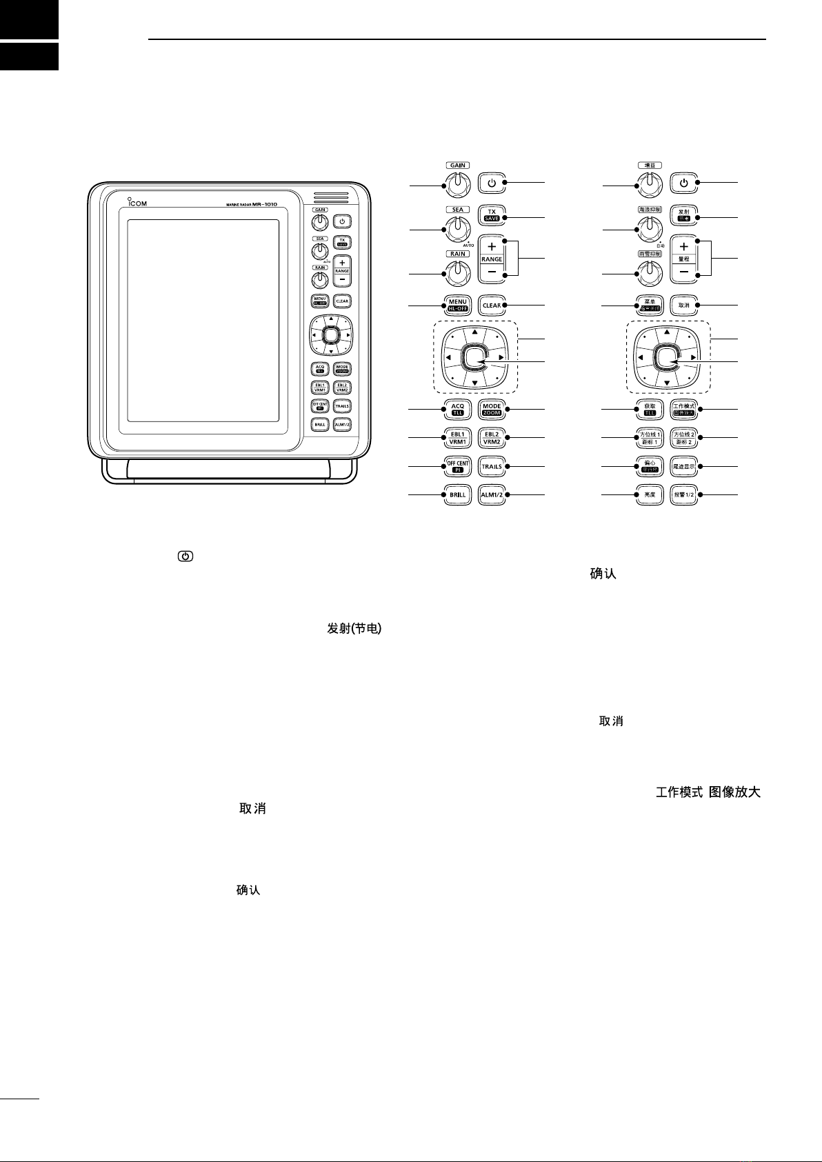
1. PANEL DESCRIPTIONS.................................. 1–6
■Front panel........................................................ 1
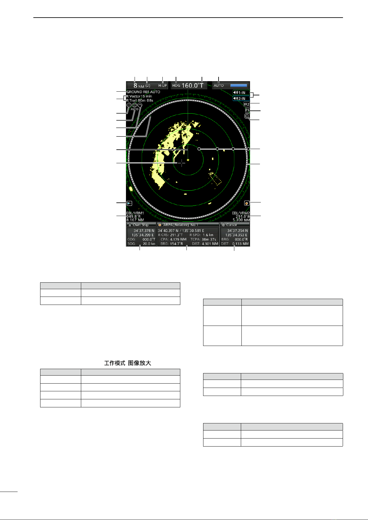
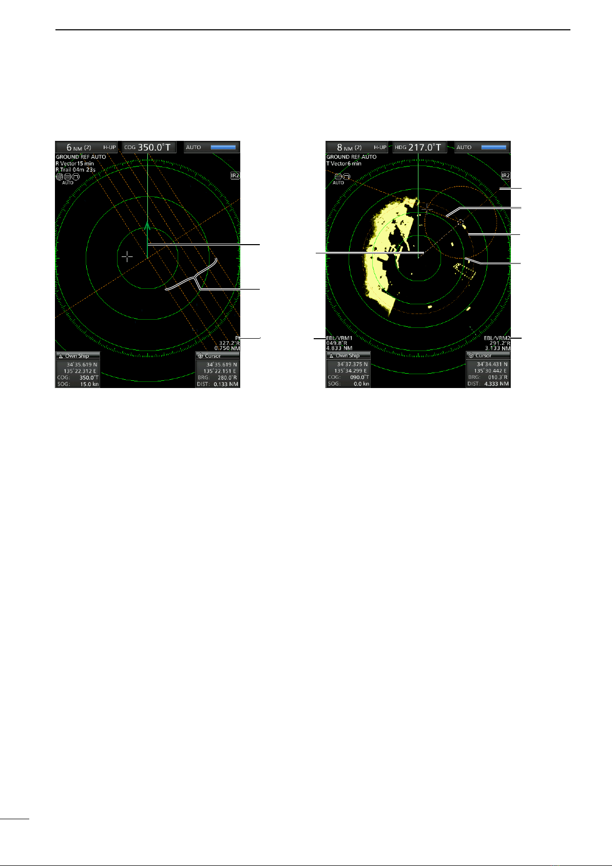
■Screen .............................................................. 3
2. BASIC OPERATION ...................................... 7–16
■Turning the Power ON or OFF.......................... 7
■Basic operation ................................................. 7
■Adjusting brilliance and color ............................. 8
■Adjusting the screen ......................................... 9
■OFF CENTER function ................................... 10
■Zoom function ................................................ 10
■Interference Rejection function ....................... 10
■Echo Stretch function.......................................11
■Long pulse function..........................................11
■Trail function ................................................... 12
■Power save function ....................................... 13
■Ship speed indication...................................... 14
■Waypoint indication......................................... 14
■Bearing settings .............................................. 15
3. DISTANCE AND DIRECTION MEASUREMENTS..17–20
■Distance measurement................................... 17
■Bearing and Distance measurement .............. 18
■Advanced measurements ............................... 19
4. ALARM FUNCTION..................................... 21–22
■Setting the Alarm zone.................................... 21
■Setting Zone alarm type.................................. 22
5. THE SIMPLIFIED ARPA OPERATION ........ 23–25
■ARPA operation............................................... 23
■Descriptions of ARPA targets.......................... 24
■ARPA settings ................................................. 25
■Related settings .............................................. 25
6. AIS RECEIVER ............................................ 26–31
■About AIS........................................................ 26
■AIS operation .................................................. 26
■Description of the AIS display ......................... 27
■AIS settings..................................................... 29
■Related settings .............................................. 31
7. OTHER FUNCTIONS................................... 32–38
■Receiving DSC Information ............................ 32
■TLL function .................................................... 33
■Select the language ........................................ 34
■Simulation mode ............................................. 34
■Antenna rotation speed................................... 35
■Timing adjustment........................................... 35
■Heading adjustment........................................ 36
■Range selection .............................................. 37
■Save and load settings ................................... 37
■Resetting......................................................... 38

1
PANEL DESCRIPTIONS
1
qPOWER KEY (p. 7)
zPush to turn the radar power ON or OFF.
• The initial screen is displayed and a beep sounds
after the power has been turned ON.
wTRANSMIT/SAVE KEY [TX (SAVE)]/ [ ]
zPush to toggle between the TX mode and the
standby mode. (p. 7)
zHold down for 1 second to turn ON the power
save function. The radar for the TX interval scan
is xed at 10 revolutions. (p. 13)
LSelect the save time in the System menu.
e RANGE UP/ DOWN KEYS [+]/[–] (p. 7)
zPush [+] to increase the screen range.
zPush [–] to decrease the screen range.
rCLEAR KEY [CLEAR]/[ ]
zPush to cancel the Submenu or Option selection
mode in the Menu screen. (p. 39)
zHold down for 1 second to turn the activated AIS
target into a sleeping target. (p. 26)
LHold down [ENTER]/[ ] for 1 second to change
the sleeping AIS target to an activated target.
zHold down for 1 second to release the ARPA
target or delete the TLL symbol. (pp. 23, 33)
tCURSOR PAD
zPush to move the cross-line cursor in sixteen
directions in the normal operating mode.
zSets the EBLs, VRMs, alarm area, ARPA target,
AIS target, and so on.
zPush [t] or [u] to select the Menu group, or
push [p] or [q] to select the menu items in the
Menu screen. (p. 39)
yENTER KEY*
*Described as [ENTER]/[ ] in this manual.
Push to select the target and display the ARPA,
AIS, DSC, TLL, or WPT information. (pp. 14, 23,
26, 33)
zIn the Menu screen, push to display a submenu
or option selection mode, or push to save the
settings. (p. 39)
zHold down for 1 second to turn the sleeping AIS
target into an activated target. (p. 26)
LHold down [CLEAR]/[ ] for 1 second to change
the activated AIS target to a sleeping target.
zHold down for 1 second to display the DSC
details. (p. 32)
u
MODE / ZOOM KEY [MODE•ZOOM]/
[ • ]
zPush to select the screen mode, Head-up (H-
UP), Course-up (C-UP), North-up (N-UP) or True
motion (TM) screen. (p. 7)
LThe North-up, and Course-up screens can
be selected only when a bearing data input is
connected. (pp. 45, 53)
LThe TM screen requires bearing data and position
data.
LTheTM screen is not selectable in the 32 NM or
higher range.
zHold down for 1 second to toggle the ZOOM
view ON or OFF. The ZOOM view expands the
Plain Position Indicator (PPI) and the trail around
the cross-line cursor to the double size of the
normal view. (p. 10)
q
w
t
u
y
Control panel (English) Control panel (Chinese)
r
i
o
!0
!7
!8
!6
!5
!4
!3
!2
!1
e
q
w
t
u
y
r
i
o
!0
!7
!8
!6
!5
!4
!3
!2
!1
e
■Front panel

2
1
PANEL DESCRIPTION
i EBL2 (VRM2) KEY [EBL2 (VRM2)]/
[](pp. 17–20)
zPush to display the EBL2 and the VRM2.
EBL: Electronic Bearing Line
VRM: Variable Range Marker
• Push [t] or [u] to adjust the EBL selector, or push
[p] or [q] to adjust the VRM selector. Then push
[ENTER]/[ ] to set the point.
• The EBL2 bearing and the VRM2 distance are
displayed in the lower right corner of the screen.
• When EBL1 and VRM1 are displayed, the center of
the VRM2 appears at the intersection point of the
EBL1 and the VRM1.
oTRAILS KEY [TRAILS] / [ ](p. 12)
zPush to turn the trail function ON or OFF. This
is useful for watching other ship’s tracks, and
approximate relative speed.
LThe Trail settings can be changed in the Trail
menu.
zHold down for 1 second to erase the plotted
echoes when the trail function is ON.
!0 ALARM KEY [ALM1/2]/[ 1/2](pp. 21–22)
zPush to select the Alarm function, ALM1, ALM2,
ALM1 & ALM2, or OFF.
zHold down for 1 second to enter the alarm zone
setting mode.
• Push the cursor pad to move the cross cursor to the
zone starting point, then hold down [ALM1/2]/[
1/2] for 1 second. The frame of the entered zone
appears. Then push the cursor pad to x the nish
point, and then push [ALM1/2]/[ 1/2]. The alarm
zone will automatically be formed.
!1 BRILLIANCE KEY [BRILL]/[ ] (p. 8)
zPush to display the Brill/Color setting box.
LThe brilliance of the display, the key backlight, and
display color can be adjusted in the setting box.
LThe brightness of the symbols, characters and
illuminations can be independently adjusted in the
Color menu.
zPush to increase or decrease the brilliance of
the display.
zHold down for 1 second to select the maximum
brilliance.
!2 OFF CENTER / PARALLEL INDEX LINE KEY
[OFF CENT•PI]/ [ • ] (p. 10)
zPush to turn the OFF CENTER function ON or
OFF.
LThis function is usable in the 24 NM or less ranges.
zHold down for 1 second to display or clear the
parallel index lines.(p.17)
!3 EBL1 (VRM1) KEY [EBL1 (VRM1)]/
[] (pp. 17–20)
zPush to display the EBL1 and the VRM1.
EBL: Electronic Bearing Line
VRM: Variable Range Marker
• Push [t] or [u] to adjust the EBL selector, or push
[p] or [q] to adjust the VRM selector. Then push
[ENTER]/[ ] to set the point.
• The EBL1 bearing and the VRM1 distance are
displayed in the lower left corner of the screen.
• When the EBL1 and the VRM1 are displayed, the
beginning of the EBL2 appears at the intersection
point of the EBL1 and the VRM1.
!4
ACQUIRE TARGET / TLL KEY [ACQ/TLL]/ [ •TLL]
zPush to acquire an ARPA target on the cursor.
LHold down [CLEAR]/[ ] for 1 second to release
the ARPA target.
zHold down for 1 second to output the position
information where the cursor is placed, to the
NMEA output terminals. (p. 23)
LTLL output requires bearing data and position data.
LThe target symbol can be displayed, depending on
the setting in the “TLL Mode” item of the System
menu. (p. 33)
!5 MENU KEY [MENU/HL-OFF]/[ • ]
zPush to enter or exit the Menu screen. (p. 39)
zPush [t] or [u] to select the Menu groups, or
push [p] or [q] to select the items.
zWhile holding down [MENU•HL_OFF]/[ •
], the heading line is temporarily turned
OFF.(p.9)
LThe rings or other objects can also be turned OFF
when the “HL OFF Mode” item in the System menu
is set to “All.” (p. 44)
!6 RAIN CLUTTER CONTROL
RAIN
/
(p. 7, 9)
Eliminates echoes from rain, snow, fog, and so on.
zRotate the control fully counter clockwise to
deactivate the RAIN function.
• The RAIN icon ( ) disappears.
!7 SEA CLUTTER CONTROL
SEA
/
(p. 7, 9)
Eliminates echoes from waves in close range.
Reduces the receiver gain for close objects within a
radius of approximately 8 nautical miles to eliminate
sea clutter.
zRotate the control fully clockwise to activate the
automatic SEA control function.
• The SEA icon ( ) is displayed in the upper left of
the screen.
• “AUTO” is displayed below the SEA icon ( ) when
the automatic control function is active.
LUnder normal conditions set the SEA to minimum.
LUse this control with caution when the sea is rough.
!8 GAIN CONTROL
GAIN
/ (p. 7, 9)
Adjusts the receiver amplier gain.
zRotate clockwise to increase the gain.
LThe increased gain may increase screen noise.
1
2
3
4
5
6
7
8
9
10
11
12
13
14
15
16
17
18
19
20
21

3
1PANEL DESCRIPTION
■Screen
This Display example is
set to Wide in the “PPI
Area” item of the Display
menu.
q SCREEN RANGE READOUT (p. 17)
Displays the range of the current screen.
Indicator Description
NM nautical miles
km kilometers
LThe distance unit can be selected in the Initial menu.
wFIXED RING RANGE READOUT (p. 17)
Displays the interval range of the xed ring.
eMODE INDICATOR (p. 7)
Displays the mode of the display.
Push [MODE•ZOOM]/ [ • ] to select.
Indicator Description
H-UP Head-up
C-UP Course-up
N-UP North-up
TM True Motion
LN-UP and C-UP screens require external bearing data.
LThe TM screen requires bearing data and position
data.
rHEADING INDICATOR (p. 15)
Displays the heading readout.The HDG readout
indicates the bow of the ship’s heading in a
clockwise direction from north.
Indicator Description
HDG
Displayed when the “Bearing Input” in
the Initial menu is set to “NMEA,” “N+1,”
or “AUX.”
COG
Displayed When the “Bearing Input”
item in the Initial menu is set to “GPS”
or “GPS-L.”
tBEARING REFERENCE (p. 15)
Displays the bearing reference.
Indicator Description
T True bearing
M Magnetic bearing
yTUNING MODE INDICATOR (p. 9)
Displays the tuning mode and the tuning level.
Indicator Description
Auto Auto tuning
Manual Manual tuning
• “TUNE (AUTO)” is displayed when the “TUNE” item
in the Video menu is set to “Auto” or “TUNE (MAN)” is
displayed when the “TUNE” item is set “Manual.”
uREFERENCE INDICATOR (p. 15)
Displays the basis of vector reference.
q t yw e r
!4
!3
!2
!1
!0
o
u
!5
!6 @0
@2
@3
@5
@6
@1
i
!7 !9
!8
@7
@4

4
1
PANEL DESCRIPTION
iTRAILS INDICATOR (p. 12)
Displays the trail reference and the trail time.
• The echo remains, with gradation, during the trail time
period on the screen. (Except for the trail time; ∞)
• Progressing time counter starts counting until the timer
reaches the trail time.
Indicator Description
T True
M Magnetic
oRAIN CONTROL ICON (p. 9)
Displayed when the RAIN function is in use.
!0 SEA ICON (p. 9)
Displayed when the SEA control function is in use.
“AUTO” is displayed below the icon when the
automatic SEA control function is in use.
!1 LONG PULSE ICON (p. 9)
Displayed when the long pulse is in use.
!2 NORTH MARK
The north mark indicates the true north direction.
!3 HEADING LINE (p.16)
The heading line indicates the ships bow direction.
!4 CROSS-LINE CURSOR
Used to measure the bearing and distance, setting
the alarm zone, selecting the ARPA/AIS targets,
and so on.
LThe cross-line cursor can be moved to sixteen
directions by pushing or holding a cursor pad.
!5 AIS ICON (p. 26)
Displayed when a valid VDM sentence is input
from the [NMEA1] (AIS) port.
The indicator disappears if the AIS signal is not
received for 6 minutes and 40 seconds.
!6 EBL1/ VRM1 READOUTS (pp. 17–20)
Displays the bearing of the Electronic Bearing Line
(EBL) 1 and the distance of the Variable Range
Marker (VRM) 1, when the EBL1 and the VRM1
are in use.
LNautical miles (NM) or kilometers (km) can be
selected in the Initial menu as the distance unit in the
Initial menu.
!7 OWN SHIP INFORMATION
Displays your own ship’s latitude and longitude,
course, and speed.
LTo display the position, NMEA 0183 data is required.
LThe speed unit in nautical miles (kn) or kilometers
(km/h) can be selected as the speed unit in the Initial
menu.
!8 INFORMATION BOX (pp. 14, 23, 26, 32)
Displays a detailed information of a selected target,
such as AIS, ARPA, TLL, Waypoint, or, DSC.
LRefer to each section in this manual for details on the
displayed information in each function.
!9 CURSOR INFORMATION
The current position of the cross-line cursor is
displayed.
LLatitude and longitude (Lat/Lon) or Time to go (TTG)
can be selected as the position format.
LAn external NMEA data in 0183 format is required.
• Displays the bearing and distance to the cross-line
cursor.
Indicator Description
R Relative bearing
T True bearing
M Magnetic bearing
LBearing data and position data are required.
@0 EBL2/ VRM2 READOUTS (pp. 17–20)
Displays the bearing of the Electronic Bearing Line
(EBL) 2 and the distance of the Variable Range
Marker (VRM) 2 when the EBL2 and the VRM2 are
set.
LNautical miles (NM) or kilometers (km) can be
selected as the distance unit in the Initial menu.
@1 ARPA ICON (p. 23)
Displayed when one or more targets are
automatically acquired by auto acquire function.
@2 PLAIN POSITION INDICATOR SCOPE AREA
Displays the radar picture and plots the data such
as vessels, bases, and so on.
@3 FIXED RANGE RINGS (p. 25)
Displays the distance at xed intervals from the
own position. The interval distance is indicated by
the ring range readout (w).
LThese rings are displayed when the “Ring Brill” item
in the Color menu is set to ON (1 to 3).
@4 ZOOM ICON (p. 10)
Displayed when the zoomed view is activated.
@5 ECHO STRETCH ICON (p. 11)
Displayed when the echo stretch function is in use.
@6 IR1 / IR2 ICONS / (p. 10)
Displayed when the Interference Rejection (IR)
function 1 or 2 is turned ON.
@7 ALARM1 / ALARM2 ICONS /
(p.
21–22)
Displayed when the alarm 1 or 2 is set.
1
2
3
4
5
6
7
8
9
10
11
12
13
14
15
16
17
18
19
20
21

5
5
@8 OWN SHIP VECTOR INDICATOR (p. 6)
Displays the vector of your own ship.
@9 PARALLEL INDEX LINES (p. 17)
Displayed when the Parallel Index line (PI) function
is in use. Used to measure the direction and
interval of the parallel index lines
#0 PI READOUTS (p. 17)
Displays the direction and interval of the parallel
index lines when the Parallel Index line (PI)
function is set.
■Screen (Continued)
#1 WAYPOINT MARKER (p. 14)
Displays a waypoint that is received from
navigation equipment.
• This marker is displayed when the “WPT Display” item
in the Display menu is set to ON.
• To display the Waypoint marker, bearing data and
NMEA data in 0183 format are required. (p. 53)
#2 EBL1 (pp. 17–20)
#3 EBL2 (pp. 17–20)
Used to measure bearing.
When a target is selected, the EBL/VRM1 readouts
(!6) or the EBL/VRM2 readouts (@0) display its
bearing.
#4 VRM1 (pp. 17–20)
#5 VRM2 (pp. 17–20)
Used to measure distance.
When a target is selected, the EBL/VRM1
readouts (!6) or the EBL/VRM2 readouts (@0)
display its distance.
#1
#4
#38
#5
#2
@0
!6
1PANEL DESCRIPTION
@9
#0
@8

6
6
1
2
3
4
5
6
7
8
9
10
11
12
13
14
15
16
17
18
19
20
21
#6 ALARM ZONE (p. 14)
Displays the alarm zone.
• Displays when the alarm function is in use.
#7 WARNING MESSAGE (p. 22)
Displayed at the bottom of the screen when an
alarm sounds in case such as a vessel is entered
into the zone that you have set.
• Push [CLEAR]/[ ] key to stop the alarm sound and
close the displayed message.
#8 POPUP MESSAGE (p. 32)
A message pops up when the radar received the
data of the target, such as a DSC, or favorite AIS
that you have selected.
• Push [Enter]/[ ]to display the details, or push
[CLEAR]/[ ] key to stop the alarm sound and close
the displayed message.
1
PANEL DESCRIPTION
#6
#7
#8

2
7
BASIC OPERATION
■Turning the Power ON or OFF
Refer to Chapter 14 in this manual about the
installation and connections. (pp. 54–60)
Turning ON the power
1. Push [ ] to turn ON the power.
• The magnetron inside the scanner unit warms up for
90 seconds and the warm-up time is counted down
on the screen. When the countdown is completed, the
Standby screen is displayed.
Warm-up
time
Standby
indicator
2. Push [TX (SAVE)]/[ ] to start scanning.
• Targets and heading markers are displayed.
• The screen is displayed approximately 2 seconds
after turning ON the power, when “Auto” is selected in
the “TUNE” item of the Video menu.
NOTE: At the rst turning ON the MR-1010RII or
after performing Factory Reset, the Initial Setting
screen is displayed. Push [p] or [q] to select a
language, and push [ENTER]. (p. 38)
Turning OFF the power
zPush [ ] to turn OFF the power.
■Basic operation
1. Turn ON the power. (q)
• Standby indicator is displayed after the Warm-up is
completed.
2. Adjust the display brilliance and color. (w)
3. Push [TX (SAVE)]/[ ]. (e)
4. Push [+] several times until the maximum display
range is selected. (r)
5. Rotate
GAIN
/ to adjust the gain. (t)
6. Push [+] or [–] several times to select a desired
display range. (y)
LThe screen range readout shows the range of the
screen.
7. Rotate
SEA
/
to set the sea clutter
control to minimum. (u)
8. Rotate
RAIN
/ to set the rain clutter
control to minimum. (i)
9. Push [MODE]/[ ] to select either the Head-
up: H-UP, Course-up: C-UP, North-up: N-UP or
True Motion: TM screen. (o)
LC-UP or N-UP can be selected only when bearing
data is provided. TM can be selected only when
bearing and position data is provided.
(See page 53 for details)
(English) (Chinese)
q
qt
t
u
i
i
e
e
oo
ry ry
ww
u

8
2
BASIC OPERATION
1
2
3
4
5
6
7
8
9
10
11
12
13
14
15
16
17
18
19
20
21
■Adjusting brilliance and color
DAdjusting the display brilliance
The brilliance of the screen can be adjusted. When
you require continuous operation, but not constant
viewing, a lower setting can increase the life of the
LCD.
1. Push [BRILL]/[ ] to open the Brilliance/Color
adjustment box.
2. Push [t] or [u] to adjust the display brilliance.
3. Push [CLEAR]/[ ] to close the box.
• The display automatically closes the box if you don’t
push any keys for 5 seconds.
zPush [BRILL]/[ ] to increase or decrease the
display brilliance.
zHold down [BRILL]/[ ] for 1 second to select
maximum brilliance.
NOTE: High intensity will shorten the life of the LCD
display.
DAdjusting the key backlight
The brilliance of the key backlight can be adjusted for
your convenient operation.
1. Push [BRILL]/[ ] to open the Brilliance/Color
adjustment box.
2. Push [q] to select the “Key” item.
3. Push [t] or [u] to adjust the key backlight.
4. Push [CLEAR]/[ ] to close the box.
• The display automatically closes the box if you don’t
push any keys for 5 seconds.
DSelecting the display color
The Day (white background), Night (black
background), and User settings are selectable.
1. Push [BRILL]/[ ] to open the Brilliance/Color
box.
2. Push [q] twice to select the “Color” item.
3. Push [t] or [u] to select a display color.
LYou can set the display color to the Day, Night, or
User.
4. Push [CLEAR]/[ ] to close the box.
• The display automatically closes the box if you don’t
push any keys for 5 seconds.
DCustomizing the Display color
You can customize the foreground and background
color of each color setting, in the Color menu.
See the “Menu Screen” for details. (pp.39–40)
(MENU wColor)
1. Push [MENU]/[ ] to display the Menu screen.
2. Push [t] or [u] to select the Color menu.
3. Push [p] or [q] to select the Color settings.
• The selected item is highlighted.
4. Push [ENTER]/[ ] to enter the option selection
mode.
5. Push [t] or [u] to a desired display color, then
push [ENTER]/[ ].
DBrilliance of the xed range rings
The xed range rings can be used for rough distance
measurements. (p. 25)
The brilliance of the xed range rings can be adjusted
or turned OFF.
(MENU wColor wRing Brill)
1. Push [MENU]/[ ] to display the Menu screen.
2. Push [t] or [u] to select the Color menu.
3. Push [p] or [q] to select the “Ring Brill” item.
• The selected item is highlighted.
4. Push [ENTER]/[ ] to enter the option selection
mode.
5. Push [t] or [u] to select a Ring Brilliance 1, 2, 3
or O FF.
6. Push [ENTER]/[ ] to save the setting and exit
the option selection mode.
LPush [CLEAR]/[ ] to cancel the setting and exit
the mode.
NOTE: Refer to Chapter 3 for details on the xed
range ring settings. (p.17)

9
2BASIC OPERATION
■Adjusting the screen
The followings are typical basic operation examples
that may hinder radar reception (sea clutter,
precipitation interference and echoes from other
radar). See also Basic Radar Theory in Chapter 9
(pp. 47–49)
DAdjusting the GAIN
zRotate the
GAIN
/
control clockwise to
increase, or counter clockwise to decrease the
gain.
LThe increased gain may increase screen noise.
Adjust the gain to the point where the screen noise
just disappears.
DSEA function
The SEA function eliminates echoes from waves
at close range. Reduce the receiver gain for close
objects within a radius of approximately 8 NM to
eliminate sea clutter.
zRotate the
SEA
/
control until the
echoes from sea waves disappears.
• The SEA icon ( ) is displayed in the upper left
corner of the screen when the SEA function is
active.
Adjust SEA control
Echoes from sea waves
zRotate the
SEA
/
control fully clockwise
to activate the automatic control.
• “AUTO” is displayed below the SEA icon ( ) when the
automatic control function is active.
NOTE: The
SEA
/
control reduces the
receiver sensitivity of objects within approximately
8 NM. Therefore, when the SEA setting is set to too
high, close targets are blanked.
Small objects may not be displayed on the screen
when strong echoes from rain or islands within 1
NM while the automatic SEA function is activated.
DRAIN function
This function eliminates echoes from rain, snow, fog,
and so on.
zRotate the
RAIN
/ control fully
counterclockwise to deactivate the control function.
• The RAIN icon ( ) disappears.
Adjust RAIN controlSmall echoes
DManual tuning
The receiver tuning can be manually adjusted.
(MENU wVideo wTune)
1. Push [MENU]/[ ] to display the Menu screen.
2. Push [t] or [u] to select the Video menu.
3. Push [p] or [q] to select the “TUNE” item.
• The selected item is highlighted.
4. Push [ENTER]/[ ] to enter the option selection
mode.
5. Push [t] or [u] to select “Manual,” then push
[ENTER]/[ ].
• “TUNE (MAN)” is displayed at the top of the screen.
6. Push [q] to select the “Manual TUNE” item.
• The selected item is highlighted.
7. Push [ENTER]/[ ] to enter the option selection
mode.
• If the “TUNE” item is set to “Auto,” you cannot enter
the option selection mode.
8. Push [t] or [u] to adjust the tuning level. (p. 44)
9. Push [ENTER]/[ ].
10. Push [MENU]/[ ] to exit the Menu screen.
DHeading marker
The heading marker is a line that indicates your
vessel’s bow direction. This marker will be displayed
on the center of the screen when the Head-up
screen: H-UP is selected. You can temporarily hide
the heading marker when the target is located under
the heading marker. The heading marker is hidden
while holding down the [MENU]/[ ] key.

10
2
BASIC OPERATION
1
2
3
4
5
6
7
8
9
10
11
12
13
14
15
16
17
18
19
20
21
■OFF CENTER function
The scanning area can be shifted in direction and
can be partially enlarged. This is useful when the
Head-up screen is selected, and you want to enlarge
the bow direction display, or the center of the screen
shifts in the direction of the intersection.
LThis function is selectable in 24 NM or shorter ranges.
LThis function is not selectable in the TM screen.
1. Push [OFF CENT]/[ ] to shift the screen.
2. Push [OFF CENT]/[ ] again to return to the
normal screen.
The OFF center mode setting can be changed in the
“OFF Center Mode” item in the System menu.
• 25%, 50%, 75%, and Cursor are selectable.
■Zoom function
The Zoom function expands the target to two times
normal view.
1. Move the cross-line cursor to a desired target.
2. Hold down [MODE]/[ ] for 1 second to
toggle between the zoomed view and the normal
view.
• The ZOOM icon ( ) is displayed in the upper right of
the screen.
■Interference Rejection function
Radar interference may appear when another
vessel’s radar is operating on the same frequency
band in close proximity. The Interference Rejection
(IR) function can eliminate this type of interference.
1. Push [MENU]/[ ] to display the Menu screen.
2. Push [t] or [u] to select the Video menu.
3. Push [p] or [q] to select the “IR” item.
4. Push [ENTER]/[ ] to enter the option selection
mode.
5. Push [t] or [u] to select the IR function 1, 2, or
OFF.
6. Push [ENTER]/[ ] to save the setting.
7. Push [MENU]/[ ] to exit the Menu screen.
• “IR1” or “IR2” indicator is displayed in the upper right
of the screen, when the function is activated.
OFF center view
Normal view
Zoomed view
Normal view
With IR function ON
Radar interference
(MENU wVideo wIR)

11
2BASIC OPERATION
(MENU wVideo wPulse Width)
■Echo Stretch function
The blips can be magnied electronically for easier
viewing of small targets.
1. Push [MENU]/[ ] to display the Menu screen.
2. Push [t] or [u] to select the Video menu.
3. Push [p] or [q] to select the “Echo Stretch” item.
4. Push [ENTER]/[ ] to enter the option selection
mode.
5. Push [t] or [u] to select the Echo Stretch ON.
6. Push [ENTER]/[ ] to save the setting.
7. Push [MENU]/[ ] to exit the Menu screen.
• “ES” is displayed in the upper right of the screen,
when the function is activated.
NOTE: Turn OFF this function during normal
operation.
■Long pulse function
To magnify the blips for easier viewing of small
targets, the long pulse and echo stretch functions are
usable. When the long pulse is used in the 3⁄4 to 3 NM
range, this function magnies target echoes behind
the target.
1. Push [MENU]/[ ].
2. Push [t] or [u] to select the Video menu.
3. Push [p] or [q] to select the “Pulse Width” item.
4. Push [ENTER]/[ ] to enter the option selection
mode.
5. Push [t] or [u] to select SP (Short Pulse) or LP
(Long Pulse).
• When “LP” is selected, “ ” appears in the upper left
of the screen.
6. Push [ENTER]/[ ] to save the setting.
7. Push [MENU]/[ ] to exit the Menu screen.
NOTE: Selecting SP (Short Pulse) increases the
target distance resolution. (p. 43)
With Echo Stretch ON
Normal screen
(MENU wVideo wEcho Stretch)

12
2
BASIC OPERATION
1
2
3
4
5
6
7
8
9
10
11
12
13
14
15
16
17
18
19
20
21
■Trail function
The trail function memorizes echoes continuously or
at constant intervals. This is useful for watching other
vessels’ tracks, approximate relative speed and so
on.
DUsing the Trail function
1. Push [TRAILS]/[ ] to turn ON the Trail
function.
• The trail indicator and the trail interval are displayed
in the upper left of the screen.
• The trail interval counter starts to count up to the trail
time.
2. All echoes higher than the specified level at the
plotted time are memorized and displayed with
a graduated intensity together with the current
echoes.
• Echoes are displayed with minimum intensity when
“∞” is selected.
LHold down [TRAILS]/[ ] for 1 second to reset
the trail interval counter and the plotted echoes.
3. Push [TRAILS]/[ ] to cancel the Trail
function and erase the plotted echoes.
• The trail indicator and the trail interval disappear.
Trail time
Trail indicator Trail interval counter
DCustomizing the trail settings
You can customize the trail settings in the Trail menu
of the Menu screen.
1. Push [MENU]/[ ] to display the Menu screen.
2. Push [t] or [u] to select the Trail menu.
3. Push [p] or [q] to select an item.
LThe selectable settings are described below.
4. Push [ENTER]/[ ] to enter the option selection
mode.
5. Push [t] or [u] to select an option.
6. Push [ENTER]/[ ] to save the setting.
7. Push [MENU]/[ ] to exit the Menu screen.
(MENU wTrail)
Reference
• True: Regardless of the movement of your
vessel, the trail of other vessels displays a
real movement over ground. Therefore, a
stopped target's trail is not displayed. The
True trail requires a heading signal and
your own vessel's position information.
• Relative: The trail of other vessels is relative to
your vessel. In this mode, other vessels’
movement and your vessel’s movement
are combined, so, Relative trail is valid if
you want to look at the relative movement
to avoid collisions. However, a stopped
target’s trail is also displayed. In that
case, it is difcult to see in some places
such as near islands.
LRegardless of this setting, the display acts as:
• The Relative trail setting when the Head-UP (H-UP)
screen is selected.
• The True trail setting when the True motion (TM)
screen is selected.
Time
Selects the trail time from 30 seconds, 1 minute, 3
minutes, 6 minutes, 15 minutes, or ∞(continuous)
Color
Selects the trail time from Blue, Yellow, Green, Red,
Orange, and White.
Level
• Low: Leaves a trail between Low and High levels.
• Middle: Leaves a trail between Mid and High levels.
• High: Leaves a trail only at the High level.

13
2BASIC OPERATION
■Power save function
The power save function conserves the vessel's
battery power by pausing the transmission. The
standby (pausing) times are selectable (rotation
number is xed to 10).
For example, when 1 minute is selected, the scanner
rotates 10 revolutions, then stops for 1 minute, and
then repeats this sequence while the power save
mode is activated.
DSetting the scanning standby time
1. Push [MENU]/[ ]
2. Push [t] or [u] to select the System menu.
3. Push [p] or [q] to select the “Save Time” item.
4. Push [ENTER]/[ ] to enter the option selection
mode.
5. Push [t] or [u] to select the standby time.
L1, 6, 15, and 30 minutes are selectable.
6. Push [ENTER]/[ ] to save the setting.
7. Push [MENU]/[ ] to exit the Menu screen.
DEntering the power saving mode
1. Hold down [TX (SAVE)]/[ ] for 1 second
to enter the power save mode.
• The “SAVE” indicator is displayed in the upper right of
the screen.
2. After the scanning rotations are finished,
transmission and rotation are suspended until the
selected standby time elapses.
• “SAVE” and standby time are displayed in the upper
right of the screen and the standby time is counted
down.
• After the selected standby time elapses, transmission
and rotation restart.
3. Push [TX (SAVE)]/[ ] to cancel the power
save function.
• The save indicator turns OFF.
NOTE: You can save more power by using the
Power save function with the Alarm function. In this
case, the LCD display is turned OFF until an object
enters the programmed alarm zone. (p. 21)
Counts down
the standby
time
Scan and STBY modes alternate
(MENU wSystem wSave Time)

14
2
BASIC OPERATION
1
2
3
4
5
6
7
8
9
10
11
12
13
14
15
16
17
18
19
20
21
■Ship speed indication
When the ship speed data in NMEA 0183 format is
applied, the radar can display the ship speed.
1. Push [MENU]/[ ].
2. Push [t] or [u] to select the Initial menu.
3. Push [p] or [q] to select the “Speed Unit” item.
4. Push [ENTER]/[ ] to enter the option selection
mode.
5. Push [t] or [u] to select the desired speed unit.
Lknot (kn) or kilometers/hour (km/h) is selectable.
6. Push [ENTER]/[ ] to save the setting.
7. Push [MENU]/[ ] to exit the Menu screen.
■Waypoint indication
When waypoint data received from navigation
equipment in NMEA 0183 format is applied, the radar
can display the waypoint.
To display the waypoint marker, bearing data and
position data are required. (p. 53)
DDisplaying the waypoint marker
1. Push [MENU]/[ ].
2. Push [t] or [u] to select the Display menu.
3. Push [p] or [q] to select the “WPT Display” item.
4. Push [ENTER]/[ ] to enter the option selection
mode.
5. Push [t] or [u] to turn the setting ON or OFF.
6. Push [ENTER]/[ ] to save the setting.
7. Push [MENU]/[ ] to exit the Menu screen.
(MENU wInitial wSpeed Unit)
(MENU w Display wWPT Display)
DWaypoint information
1. Move the cross-line cursor on the waypoint mark
or line.
2. Push [ENTER]/[ ] to display the information.
• The target identication (ID), position, Time to go
(TTG), bearing (BRG), and distance (DIST) are
displayed in the information box.
Ship Speed
Indicator
Waypoint marker

15
2BASIC OPERATION
■Bearing settings
The radar bearing interface accepts NMEA, N+1,
AUX, or COG data format and the bearing can use a
magnetic or true north type. When a true north type
bearing is used, the variation from magnetic north
can be adjusted on 0.1˚ steps.
DSetting the bearing input
1. Push [MENU]/[ ].
2. Push [t] or [u] to select the Initial menu.
3. Push [p] or [q] to select the “Bearing Input ”
item.
4. Push [ENTER]/[ ] to enter the option selection
mode.
5. Push [t] or [u] to select the bearing data source.
LNMEA, N+1, AUX, GPS, or GPS-L is selectable.
LGPS and GPS-L uses the COG (Course Over
the Ground) data as the bearing. However, if
the vessel's speed is less than 3 knots, direction
accuracy falls. Moreover, the position accuracy or
the current actual course may vary, therefore the
radar may display incorrect direction.
6. Push [ENTER]/[ ] to save the setting.
7. Push [MENU]/[ ] to exit the Menu screen.
DSetting the bearing type
1. Push [MENU]/[ ].
2. Push [t] or [u] to select the System menu.
3. Push [p] or [q] to select the “Bearing Mode”
item.
4. Push [ENTER]/[ ] to enter the option selection
mode.
5. Push [t] or [u] to select the Bearing mode.
LTrue and Magnetic north type are selectable.
LAll displayed bearing readouts show the selected
bearing type.
6. Push [ENTER]/[ ] to save the setting.
7. Push [MENU]/[ ] to exit the Menu screen.
T: True north
M: Magnetic north
(MENU wSystem wBearing Mode)
Other manuals for MR-1010RII
1
Table of contents
Other Icom Marine Radar manuals

Icom
Icom MR-1200RII User manual

Icom
Icom MR-570R User manual

Icom
Icom MR-570R User manual

Icom
Icom MR-1200RII User manual

Icom
Icom MR-1220 Series User manual

Icom
Icom MR-1200TIII User manual

Icom
Icom MR-1000TIII User manual

Icom
Icom MR-1210RII User manual

Icom
Icom MR-1000RII User manual

Icom
Icom MR-1000RII User manual