Icom MR-1220 Series User manual

INSTRUCTION MANUAL
MARINE RADAR
MR-1220 series

i
INTRODUCTION
Thank you for choosing this Icom product. This product is designed and built with Icom’ s state of the art
technology and craftsmanship. With proper care, this product should provide you with years of trouble-free
operation.
■IMPORTANT
READ ALL INSTRUCTIONS carefully completely before using the marine radar.
SAVE THIS INSTRUCTION MANUAL— This instruction manual contains basic operating instructions for the
following MR-1220 series marine radar
:
MODEL NAME DISPLAY UNIT SCANNER UNIT
MR-1220R4
MR-1220
12.1-inch color display unit
SC-R40 (Radome type)
MR-1220T4 SC-T40 (Open array, 4 kw, 4 ft type)
MR-1220T6 SC-T60 (Open array, 6 kw, 4 ft type)
MR-1220T6L SC-T60L (Open array, 6 kw, 6.5 ft type)
■SUPPLIED ACCESSORIES
LSome accessories are not supplied, depending on the radar version.
zMR-1220: Display unit
Quantity
• Front cover ............................................................. 1
• NMEA connector (PLT-167-P-R) ............................ 1
• NMEA connector (PLT-168-P-R) ............................ 1
• Spare fuse (FGB 15 A) ........................................... 1
• Spare fuse (FGB 5 A:
for over 24 V power supply
).. 1
• DC power cable...................................................... 1
• Mounting bracket.................................................... 1
• Mounting knob bolts ............................................... 2
• Installation bolts (M6×30) ....................................... 5
• Installation nuts (M6) .............................................. 5
• Spring washers (M6) ........................................... 10
• Flat washers (M6)................................................. 10
• Instruction manual (this manual) ............................ 1
• Template for display unit......................................... 1
zSC-R40: Scanner unit (Radome type)
Quantity
• System cable (15 m) .............................................. 1
• Installation bolts (M10×50) ..................................... 4
• Installation bolts (M10×25) ..................................... 4
• Installation nuts (M10) ............................................ 4
• Flat washers (M10)................................................. 4
• Spring washers (M10) ............................................ 4
• Template for scanner unit ....................................... 1
zSC-T40/SC-T60/SC-T60L:
Scanner units (Open array type)
Quantity
• System cable (20 m) .............................................. 1
• Installation bolts (M10×40) ..................................... 4
• Installation nuts (M10) ............................................ 4
• Flat washers (M10)................................................. 4
• Spring washers (M10) ............................................ 4
• Allen wrench........................................................... 1
• Cap bolts (M8×18 mm)........................................... 4
• Belleville washers (8L) ........................................... 4
• Sealing washers (T) ............................................... 4
• Flat washers (M8)................................................... 4
• Flat washers (AW) .................................................. 4
• Ferrite EMI lter...................................................... 1
• Silicon sealant ........................................................ 1
• Template for scanner unit ....................................... 1

ii
INTRODUCTION
Icom is not responsible for the destruction, damage
to, or performance of any Icom or non- Icom
equipment, if the malfunction is because of:
• Force majeure, including, but not limited to, res,
earthquakes, storms, oods, lightning, other
natural disasters, disturbances, riots, war, or
radioactive contamination.
• The use of Icom radars with any equipment that is
not manufactured or approved by Icom.
■FEATURES
The MR-1220 series marine radars are designed
especially for shing boats. They have powerful
transmitting power, a 12.1-inch Color LCD display and
many other advanced features.
zThe Simplied ARPA (Automatic Radar Plotting
Aids) function tracks up to 30 targets
(including up to 20 automatic acquiring targets)
zThe Plot function tracks your route on the radar
echo
zBuilt-in 3D Bird’s-eye view
zThe DSC (Digital Selective Calling) information
function shows received DSC Messages with Icons
zAn External Alarm can be connected to warn of
danger in a noisy environment
zBuilt-in AIS (Automatic Identication System)
overlay function
zThe Multiple language display
zA Sub display is connectable
LAn optional UX-234 video output unit is required.
Icom, Icom Inc. and the Icom logo are registered trademarks
of Icom Incorporated (Japan) in Japan, the United States,
the United Kingdom, Germany, France, Spain, Russia,
Australia, New Zealand, and/ or other countries.
All other products or brands are registered trademarks or
trademarks of their respective holders.
This marine radar is supplemental aids
to navigation and is not intended to be
a substitute for accurate and current
nautical charts.
■EXPLICIT DEFINITIONS
WORD DEFINITION
RDANGER! Personal death, serious injury or an
explosion may occur.
RWARNING! Personal injury, re hazard, or electric
shock may occur.
CAUTION Equipment damage may occur.
NOTE
If disregarded, inconvenience only.
No risk of personal injury, re or
electric shock.
■RECOMMENDATION
CLEAN THE DISPLAY UNIT THOROUGHLY with
a soft, damp (fresh water) cloth, then dry it before
operating.
Otherwise, the display unit’s keys, switches may
become unusable, due to salt crystallization.
LThe connectors on the rear panel meet IPX4
requirements while connecting to the scanner unit.
NOTE: If the display unit’s splash resistance appears
defective, carefully clean it with a soft, damp (fresh
water) cloth, then dry it before operating.
The display unit may lose its splash resistance if the
case, or connectors are cracked or broken, or the
display unit has been dropped. Contact your Icom
distributor or your dealer for advice.
■TO DETECT SART SIGNALS
SART signals may no be detected and displayed on
the screen, depending on the SEA, RAIN, and IR
settings.
Make the settings below to detect a SART signal on
the screen.
1. Set the screen range to between 6NM and 12
NM with Range ( ) [+] or [–].
2. Set the GAIN control (
GAIN
/ ) as high as
possible.
3. Minimize the SEA control (
SEA
/).
4. Minimize the RAIN control (
RAIN
/).
5. Turn OFF the Interference Reduction (IR)
function.
6. Turn OFF the Echo stretch (ES) function.

iii
INTRODUCTION
■PRECAUTIONS
DFor Display unit:
RWARNING! NEVER let metal, wire or other objects
contact the inside of the display unit, or make incorrect
contact with connectors on the rear panel.
This could cause an electric shock or damage the
display unit.
RWARNING! NEVER apply AC voltage to the DC
connector of the display unit. This could cause a re
or damage the display unit.
RWARNING! NEVER apply more than 42 V DC to
the DC connector of the display unit. This could cause
a re or damage the display unit.
RWARNING! NEVER touch or operate the display
unit with wet hands. This could cause an electric
shock or damage the display unit.
RWARNING! NEVER open the display unit. There
are no user adjustment points. This could cause an
electric shock and incorrect reassembly may cause a
re hazard.
RWARNING! NEVER operate the radar during a
lightning storm. It may result in an electric shock,
cause a re or damage the display unit. Always
disconnect the power source and scanner unit before
a storm.
RWARNING! NEVER reverse the DC power cable
polarity. This could cause a re or damage the display
unit.
RWARNING! NEVER remove the fuse holder on the
DC power cable. Excessive current caused by a short
could cause a re or damage the display unit.
CAUTION: DO NOT use or place the display unit in
areas with temperature below –15˚C (+5˚F) or above
+55˚C (+131˚F).
CAUTION: DO NOT use harsh solvents such as
Benzine or alcohol when cleaning, the display unit, as
they will damage the display unit surfaces.
CAUTION: DO NOT place the display unit in
excessively dusty environments.
DO NOT place the display unit near heating
equipment or in direct sunlight or where hot or cold air
blows directly onto it.
DO NOT place the display unit in areas that could
block air passage or put anything around the display
unit. This will obstruct heat dissipation.
KEEP the display unit out of the reach of unauthorized
persons.
KEEP the display unit away from heavy rain, and
never immerse it in the water.
The display unit meets IPX4 requirements for splash
resistance when the supplied connection cable,
scanner unit are connected.
However, if it is dropped, splash resistance cannot be
guaranteed because of possible damage to the case
or the waterproof seals.
The LCD display may have cosmetic imperfections
that is displayed as small dark or light spots. This is
not a malfunction or defect, but a normal characteristic
of LCD display.
DFor Scanner unit:
RDANGER: HIGH VOLTAGE! NEVER open the
scanner unit. The scanner unit contains high voltage
that could be fatal. And there are no user adjustment
points. All repairs and adjustments MUST be made
by a qualied electronics technician at your Marine
Navigation Dealer.
DFor qualied electronics technician
only:
RDANGER: HIGH VOLTAGE! High voltages of up
to 3,500 volts are used in the scanner unit. Although
prudent measures for safety have been adopted,
sufcient care must be taken in the operation,
maintenance and adjustment of the scanner unit.
Electric shock of 1,000 volts or more may cause
electrocution and death, even an electric shock of only
100 volts may be fatal.
RDANGER: HIGH VOLTAGE! DO NOT turn OFF
the radar’s power and do not reach inside the scanner
unit before you have:
• discharged the capacitors by disconnecting the
system cable from the radar unit for 5 minutes.
• checked that no electric charges remain inside
the device.
Also, it is recommended to wear dry insulated rubber
gloves. NEVER use both hands simultaneously, keep
one hand in your pocket.
RWARNING: RADIATION HAZARD!
Radiation emitted from the scanner unit can be
harmful, particularly to your eyes. To avoid harmful
radiation, turn OFF the radar’s power before working
on the scanner unit.
DO NOT use or place the scanner unit in areas with
temperature below –25˚C (–13˚F) or above +70˚C
(+158˚F).
NEVER immerse the scanner unit in the water. The
scanner unit meets IPX6* requirements for high-
pressure water jet resistance.
However, if the scanner unit is dropped, high-pressure
water jet resistance cannot be guaranteed because of
possible damage to the cases or the waterproof seals.
* Except for the cable connectors. They meet IPX4
requirements while connecting to the scanner unit.

iv
INTRODUCTION
■TABLE OF CONTENTS
■IMPORTANT...................................................... i
■SUPPLIED ACCESSORIES.............................. i
■FEATURES .......................................................ii
■TO DETECT SART SIGNALS ...........................ii
■EXPLICIT DEFINITIONS...................................ii
■RECOMMENDATION........................................ii
■PRECAUTIONS ...............................................iii
■TABLE OF CONTENTS ...................................iv
1 PANEL DESCRIPTION ........................................ 1
Front panel ........................................................... 1
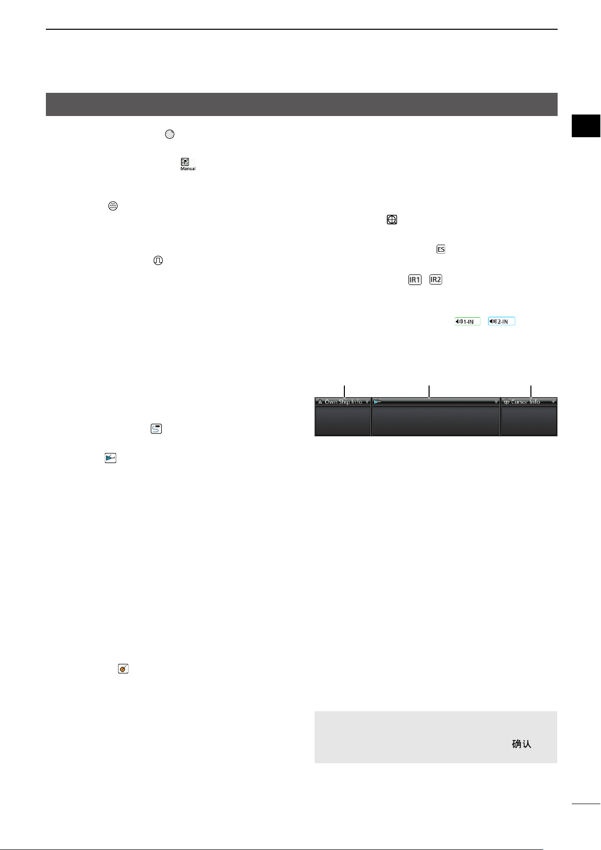
Function display ................................................... 3
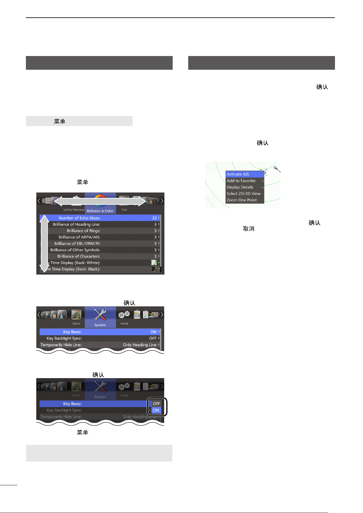
Menu screen operation......................................... 5
Using the context menu........................................ 5
2 BASIC OPERATION ............................................ 6
Turning the power ON or OFF.............................. 6
The typical boot up operation ............................... 6
Adjusting the screen brilliance and color.............. 7
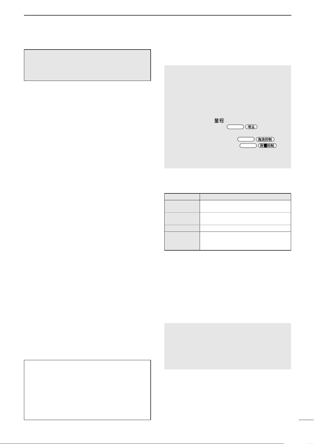
Adjusting the radar reception ............................... 8
Selecting a screen mode...................................... 9
Reference settings ............................................. 10
Changing the screen view ...................................11
Magnifying small targets..................................... 13
Power Save mode .............................................. 13
Trail function ....................................................... 14
Basic radar theory .............................................. 15
3 D
ISTANCE AND DIRECTION MEASUREMENTS
.. 17
Distance measurement ...................................... 17
Bearing and distance measurement................... 19
Advanced measurements................................... 20
4 ALARM FUNCTION........................................... 21
Using an Alarm function ..................................... 21
5 AIS RECEIVER .................................................. 23
About AIS ........................................................... 23
AIS description ................................................... 23
AIS operation...................................................... 25
AIS settings ........................................................ 28
■AIS menu........................................................ 28
■Related settings.............................................. 28
6 THE SIMPLIFIED ARPA OPERATION .............. 29
The Simplied ARPA function............................. 29
ARPA Operation ................................................. 29
ARPA settings..................................................... 32
■ARPA menu .................................................... 32
■Related settings.............................................. 32
7 ADVANCED OPERATION ................................. 33
Receiving DSC information ................................ 33
TLL function........................................................ 34
Displaying your tracks ........................................ 35
Waypoint indication ............................................ 35
Manual tuning..................................................... 36
8 MENU SCREEN................................................. 37
Using the Menu screen ...................................... 37
Menu items......................................................... 38
■Brilliance & Color............................................ 38
■Trail ................................................................ 38
■Display............................................................ 38
■Target ............................................................. 39
■ARPA.............................................................. 39
■AIS.................................................................. 39
■Video .............................................................. 40
■System ........................................................... 40
■Initial............................................................... 42
■DSC List ......................................................... 43
■AIS List........................................................... 43
■Own AIS ......................................................... 43
■Status ............................................................. 43
■Port Monitor.................................................... 43
■Scanner Monitor............................................. 43
■Safety Message.............................................. 43
9 INSTALLATION AND CONNECTIONS ............. 44
Basic connections .............................................. 44
Selecting a location ............................................ 45
Installing the display unit .................................... 45
Installing the scanner unit (Radome type).......... 47
Installing the scanner unit (Open array types).... 49
Installing the UX-234 Video output unit .............. 52
10 MAINTENANCE................................................. 54
Periodic maintenance......................................... 54
■Display unit..................................................... 54
■Scanner unit ................................................... 54
Error messages .................................................. 55
Settings for a maintenance................................. 56
11 SPECIFICATIONS ............................................. 59
■Display unit (MR-1220)................................... 59
■Scanner units ................................................. 59
■Options........................................................... 60
External data list................................................. 61
OPEN SOURCE LICENSES.................................... 62
Appendices
Display mounting bracket template .................... 70
Operating guide
■Display information
■MR-1220 MENU screen operation
INDEX....................................................................... 74

1
Front panel
1
PANEL DESCRIPTION
MR-1 220
Function display (p. 3)
Function
keys (p. 2)
Chinese keysEnglish keys
1
2
3
4
1
2
3
4
5
6
7
8
5
6
7
8
9
1[] POWER KEY (p. 6)
Push to turn the radar power ON or OFF.
2[TX (SAVE)] / [ ] KEY (pp. 6, 13)
zPush to change the operating mode between the
TX mode and the Standby mode.
zHold down for 1 second to turn ON the Power
Save function.
3RANGE ( ) UP [ + ]/DOWN [ – ] KEYS (p. 6)
zPush [+] to increase the screen range.
zPush [–] to decrease the screen range.
4[CLEAR] / [ ] KEY
zPush to cancel the previous operation.
zPush to cancel an alarm.
zHold down for 1 second to turn the active AIS
target into a sleeping target.
zHold down for 1 second to release a ARPA target,
or delete a TLL symbol.
5GAIN CONTROL
GAIN
/ (p. 8)
Adjuststhereceiverampliergain.
zRotate clockwise to increase the gain.
6S
EA CLUTTER CONTROL
SEA
/ (p. 8)
Eliminates echoes from waves in close range.
Reduces the receiver gain for close objects within a
radius of approximately 8 nautical miles to eliminate
sea clutter.
zRotate the control fully clockwise to activate the
automatic SEA control function.
7RAIN CONTROL
RAIN
/ (p. 8)
Eliminates echoes from rain, snow, fog, and so on.
zRotate the control fully counter clockwise to
deactivate the RAIN function.
8[MENU (HL-OFF)]/[ ( )] KEY
(pp. 5, 12)
zPush to enter or exit the Menu screen.
zWhile holding down this key, the heading line
temporarily disappears.
9CURSOR PAD
zPush to move the cross-line cursor in 16
directions in the normal operating mode.
zSets the EBLs, VRMs, alarm area, ARPA target,
AIS target, and so on.
zPush[◄]or[►]toselectaMenugroup,orpush
[▲]or[▼]toselectanitemoranoptioninthe
Menu screen.
ENTER KEY
Described as [ENTER]/[ ] in this manual.
zPush to select the item or target that the cross-
line cursor points to, and display the details on
the target in the information box.
zIn the Menu screen, push to apply the selection.
zHold down for 1 second to display the Context
menu.

2
PANEL DESCRIPTION 1
1
2
3
4
5
6
7
8
9
10
11
12
13
14
15
16
17
18
19
20
21
Front panel
DFunction Keys
KEY PUSH
PAGE
HOLD DOWN FOR 1 SECOND
PAGE
[ACQ (TLL)]
[ (TLL)]
ACQUIRE TARGET
Acquires an ARPA target under the
cursor.
p. 29
TLL
• Makes a TLL maker under the cursor.
• Outputs the position data under the
cursor to the NMEA output port.
p. 34
[MODE (ZOOM)]
[ ( )]
MODE
Selects the Screen mode.
p. 9
ZOOM
• In the 2D mode, opens or closes the
Zoom view window.
• In the 3D mode, opens or closes the
2D view window.
p. 12
[EBL 1 (VRM 1)]
[ ]*
ELECTRONIC BEARING LINE 1/
VARIABLE RANGE MARKER 1
Displays or clears the EBL 1 and
VRM 1 lines.
p. 19
While setting the EBL 1 and VRM 1,
moves the EBL 1 and VRM 1 line to the
cursor.
p. 19
[EBL 2 (VRM 2)]
[ ]*
ELECTRONIC BEARING LINE 2/
VARIABLE RANGE MARKER 2
Displays or clears the EBL 2 and
VRM 2 lines.
p. 20
While setting the EBL 2 and VRM 2,
moves the EBL 2 and VRM 2 line to the
cursor.
p. 20
[OFF CENT (PI)]
[ ( )]
OFF CENTER
Shifts the center (your own vessel’s
position) on the screen downward to
increase the forward view area.
p. 12
PARALLEL INDEX LINES
Displays or hides the Parallel Index
lines for measuring the distance
between targets.
p. 18
[TRAILS]
[ ]
TRAILS
Plots or cancels trails of the movement.
p. 14
Resets the trail interval counter and the
plotted trail echoes.
p. 14
[BRILL]
[ ]
BRILLIANCE
Displays or hides the Brilliance/Color
adjustment window.
p. 7
Maximizes the display brilliance.
p. 7
[ALM 1/2]
[ 1/2]
ALARM 1/ALARM 2
Turns the Alarms ON or OFF.
Alarm1→Alarm2→Alarm1and2→OFF
p. 21
Enters the Alarm Zone Setting mode.*
p.21
* Settable only in the 2D view mode.

3
1PANEL DESCRIPTION
Function display
1SCREEN RANGE READOUT (p. 6)
Displays the range of the current screen.
NM: Nautical miles
km: Kilometers
SM: Miles
2FIXED RING RANGE READOUT (p. 17)
Displaystheintervalrangeofthexedring.
3MODE INDICATOR (pp. 9, 11)
Indicates the Screen mode. “(3D)” is displayed
while in the 3D view mode.
zPush [MODE (ZOOM)]/
[ ( )] to select.
H-UP / H-UP (3D): Head-up
SH-UP / SH-UP (3D): Stabilized Head-up
N-UP / N-UP (3D): North-up
C-UP / C-UP (3D): Course-up
TM / TM (3D): True Motion
4HEADING INDICATOR (p. 10)
Displays the heading readout.
HDG: Heading
Indicates the heading of the vessel’s bow
in a clockwise direction from north.
LDisplayed when “Bearing Input” in the Initial
menu is set to “NMEA,” “AUX” or “N+1.”
COG: Course Over the Ground
LDisplayed when “Bearing Input” in the Initial
menu is set to “GPS” or “GPS-L.”
5BEARING REFERENCE (p. 10)
Displays the bearing reference.
T: True bearing
M: Magnetic bearing
6TUNING MODE INDICATOR
Displays the Tuning mode and the Tuning level.
“Standby” is displayed while in the Standby mode.
TUNE (Auto): Auto tuning
TUNE (Manual): Manual tuning
7VECTOR INDICATOR
Displays the basis of vector reference and the
vector time.
T Vector: True vector
R Vector: Relative vector
8TRAILS INDICATOR (p. 14)
Displays the Trail Reference and the Trail Time.
LEchoes remain, with gradation, during the period of
trail time on the screen. (Except for the trail time: ∞)
LProgressing time counter starts counting until the timer
reaches the trail time.
T Trail: True trail
R Trail: Relative trail
1 5 623 4
8
Information boxes
7
LThe screen below is only an example.
9

4
PANEL DESCRIPTION 1
1
2
3
4
5
6
7
8
9
10
11
12
13
14
15
16
17
18
19
20
21
Function display
9RAIN CONTROL ICON (p. 8)
Displayed when the RAIN Control function is active.
REFERENCE INDICATOR (p. 41)
Displayed when the Input Speed Selection is set to
“Manual”.
SEA ICON (p. 8)
Displayed when the SEA Control function is active.
“AUTO” (automatic) is displayed below the icon
when the Automatic SEA control is active.
LONG PULSE ICON (p. 13)
Displayed when the Long pulse is used.
NORTH MARK (p. 9)
Indicates the true north direction.
HEADING LINE (p. 12)
Indicates the ships bow direction.
CROSS-LINE CURSOR (THE CURSOR)
Used to measure the bearing and distance, setting
the alarm zone, selecting the ARPA/AIS targets,
and so on.
The cross-line cursor can be moved in 16 directions
by pushing or holding the cursor pad.
OWN TRACK ICON (p. 35)
Displayed when the Own track is turned ON.
AIS ICON (p. 23)
Displayed when a valid AIS signal is received from
the NMEA1 (AIS) port.
The icon disappears if the AIS signal is not received
for a certain period of time.
L“FULL” is displayed below the AIS icon when the AIS
information of 100 targets is received.
EBL/VRM 1 READOUTS (p. 19)
Displays the bearing of the Electronic Bearing Line
(EBL) 1 and the distance of the Variable Range
Marker (VRM) 1, when EBL 1 and the VRM 1 are
used.
EBL/VRM 2 READOUTS (p. 20)
Displays the bearing of the Electronic Bearing Line
(EBL) 2 and the distance of the Variable Range
Marker (VRM) 2 when EBL 2 and the VRM 2 are set.
ARPA ICON (p. 30)
Displayed when one or more targets are
automatically acquired by the Auto Acquire function.
L“FULL” is displayed below the ARPA icon when 20
targets are automatically acquired.
P
LAIN POSITION INDICATOR SCOPE AREA (PPI)
Displays the radar picture and plots the data such
as vessels, bases, and so on.
LThe screen shows when the PPI Area is set to “Wide.”
FIXED RANGE RINGS (p. 17)
Displaysthedistanceatxedintervalsfromthe
vessel’s own position. The interval distance is
indicated by the ring range readout (w).
LThese rings are displayed when the “Brilliance of
Rings” item in the Brilliance & Color menu is set to ON
(1 to 3).
ZOOM ICON (p. 12)
Displayed when the Zoom view is active.
ECHO STRETCH ICON (p. 13)
Displayed when the Echo Stretch function is active.
IR 1 / IR 2 ICONS / (p. 8)
Displayed when the Interference Reduction (IR)
function 1 or 2 is active.
ALARM 1 / ALARM 2 ICONS / (p. 21)
Displayed when the alarm 1 or 2 is set.
DInformation boxes
Posn: 34°34.368 N
135°22.581 E
COG: 350.0°T
SOG: 15.0 kn
Posn: 34°34.707 N
135°20.550 E
BRG: 291.3°R
Dist: 1.707 NM
499999992 SIM2
T CRS: 330.0°T T SPD: 17.0 kn
CPA: 0.092 NM TCPA: -18m 42s
BRG: 282.4°R Dist: 1.839 NM
AIS(True) Class A
1 2 3
1OWN SHIP INFORMATION BOX
Displays the current location of your vessel.
LTo display the position, NMEA 0183 data is required.
2TARGET INFORMATION BOX
Displays information about the selected target, such
as where it is a vessel, base, aircraft, waypoint
mark, and so on.
The items displayed in the box vary, depending
on the selected target. See the later sections
for details on the target type and contents in the
information box.
3CURSOR INFORMATION BOX
Displays the location of the cross-line cursor and
bearing and distance from your own position.
Bearing R: Relative bearing
T: True bearing
M: Magnetic bearing
LLatitude and longitude (Lat/Lon) or Time to go (TTG)
can be selected as the position format.
NOTE: You can minimize or restore the information
boxes. Move the cursor onto a box (the box frame
is highlighted orange), and press [ENTER]/[ ] to
minimize or restore the information box.

5
1PANEL DESCRIPTION
Using the context menu
The radar can display a context menu to shortcut to
frequently used functions, by holding [ENTER]/[ ]
for 1 second.
LThe items in the context menu vary, depending on your
operating situation, for example, selected target, display
mode, and so on.
1. Move the cursor to a target.
• The target icon is highlighted in orange.
2. Hold down [ENTER]/[ ] for 1 second.
• The context menu is displayed.
(Example: An AIS target)
3. Select an item, and then push [ENTER]/[ ].
LPush [CLEAR]/[ ] to return to the PPI screen.
4. Do the operation in the selected function.
Menu screen operation
You can customize the infrequently changed values or
function settings in the Menu screen.
Routes in the Menu screen, setting screen and the
setting items are described in the following manner:
[MENU]/[ ] > System > Key Beep
This shows the “Key Beep” item in the “System”
menu.
The typical operation in the menu screen is as follows:
(Example: Turning OFF the Key Beep)
1. Push [MENU]/[ ].
• The menu screen is displayed.
Menu
Item
2. Push[◄]or[►]toselectamenu.
(Example: System)
3. Push[▲]or[▼]toselectanitem(Example:Key
Beep), and then push [ENTER]/[ ].
4. Push[▲]or[▼]toselectanoption(Example:
OFF), or increasing or decreasing the value, and
then push [ENTER]/[ ] to apply.
5. Push [MENU]/[ ] to exit the menu screen.
NOTE: The Menu screen disappears 10 seconds
after the last operation.
See the Menu screen section for details on each
menu or setting item in the Menu screen. (p. 37)

6
1
2
3
4
5
6
7
8
9
10
11
12
13
14
15
16
17
18
19
20
21
2
BASIC OPERATION
Turning the power ON or OFF
DTurning ON the radar
1. Push [ ] to turn ON the radar.
• The magnetron inside the scanner unit warms up for
90 seconds, and the warm-up time is counted down
on the screen.
• After the countdown is completed, the radar enters
the Standby mode.
2. Push [TX (SAVE)]/[ ] to start scanning.
• Target and heading markers are displayed.
• When the TUNE setting in the Video menu is set
to “Auto,” the screen is displayed approximately 2
seconds after turning on the radar.
NOTE: At the rst turning on the radar or after
resetting it to the factory default, the Initial Setting
screen is displayed. Push [▲] or [▼] to select a
language, and then push [ENTER].
DTurning OFF the radar
zPush [ ] to turn OFF the radar.
The typical boot up operation
The image of the radar changes with the inuence of
such as weather waves or rain, surrounding terrain,
bridges and radar interference from other vessels.
Every time turning on the radar, do the following steps
so that you can get a clearer view on the screen.
1Turn ON the radar.
2Adjust the screen brilliance and color. (p. 7)
3After the radar enters standby, push [TX (SAVE)]/
[] to start transmitting.
4Push [+] several times to maximize the screen
range. (p. 17)
5Rotate
GAIN
/ to adjust the gain (sensitivity).
(p. 8)
6Push [–] to set the screen range as you prefer.
7Rotate
SEA
/ to adjust the sea clutter
control. (p. 8)
8Rotate
RAIN
/ to adjust the rain clutter
control. (p. 8)
9Push [MODE]/[ ] to select the display mode.
(p. 9)
11
22
33
88
99
44
55
66
77
English keyboard Chinese keyboard

7
2BASIC OPERATION
Adjusting the screen brilliance and color
You can adjust the screen and key backlight according
to the weather or brightness of surroundings to get
better viewing.
zPush [BRILL]/[ ] to open the “Brilliance/Color”
window.
DAdjusting the display brilliance
1. Push [▲] or [▼] to Select “Display” in the
Brilliance/Color window.
2. Push [◄] or [►] to adjust the display brilliance.
3. Push [CLEAR]/[ ] to close the window.
LThe window automatically closes if you do not push
any keys for 5 seconds.
You can increase or decrease the brilliance by
pushing [BRILL]/[ ] repeatedly.
Hold down [BRILL]/[ ] for 1 second to maximize
the brilliance.
NOTE: When you require continuous operation, but
not constant viewing, a lower setting can increase
the life of the display backlight.
TIP: Customizing the brilliance of the items on
the screen
You can individually adjust the brilliance of the
displayed items such as xed range rings, target
icons, characters, and so on.
See the “Menu screen” section for details.
[MENU]/[ ] > Brilliance & Color
DAdjusting the key backlight
The brilliance of the key backlight can be adjusted for
your convenient operation.
1. Push [▼] or [▲] to Select “Key” in the Brilliance/
Color window.
2. Push [◄] or [►] to increase or decrease the key
backlight brightness.
3. Push [CLEAR]/[ ] to close the window.
LThe window automatically closes if you do not push
any keys for 5 seconds.
DSelecting the display color
You can select the display color from Day (white
background), Night (black background), and User
setting.
Day colorNight color
1. Push [▼] or [▲] to select “Color” in the Brilliance/
Color window.
2. Push [◄] or [►] to select a display color.
3. Push [CLEAR]/[ ] to close the window.
LThe window automatically closes if you do not
push any key for 5 seconds.
TIP: Customizing the Display color
You can customize the foreground and background
color of each color setting, in the Brilliance & Color
menu.
See the “Menu screen” section for details.
[MENU]/[ ] > Brilliance & Color

8
BASIC OPERATION 2
1
2
3
4
5
6
7
8
9
10
11
12
13
14
15
16
17
18
19
20
21
The following is typical operation examples that
may hinder radar reception (sea clutter, precipitation
interference and echoes from other radar).
DAdjusting the gain
The control adjusts the sensitivity of the receiving
signal. The increased gain may increase screen noise.
zRotate the
GAIN
/ control until the noise
disappears.
DReducing the sea clutter
You can eliminates echoes from waves at close range.
Reduce the receiver gain for close objects within a
radius of approximately 8 NM to eliminate sea clutter.
zRotate the
SEA
/ control until the echoes
from sea waves disappear.
• The SEA icon is displayed in the upper left corner
of the screen when the SEA function is active.
Echoes from the sea waves
zRotate the
SEA
/ control fully clockwise
to activate the automatic control.
• “AUTO” is displayed below the SEA icon when the
automatic control is active.
NOTE:
• The
SEA
/ control reduces the receiver
sensitivity of objects within approximately 8 NM.
Therefore close targets are blanked if the SEA
setting is set to too high.
• While the automatic SEA function is activated,
small objects may not be displayed on the screen
due to strong echoes from rain or islands within
1 NM.
DReducing the rain clutter
The rain clutter control eliminates echoes from rain,
snow, fog, and so on.
zRotate the
RAIN
/ control fully
counterclockwise to deactivate the control function.
LThe RAIN icon disappears.
Adjust RAIN controlSmall echoes
DInterference Reduction function
Radar interference may be displayed when another
vessel’s radar is operating on the same frequency
band in close proximity. The Interference Reduction
(IR) function can eliminate this type of interference.
[MENU]/[ ] > Video > Interference Reduction
(IR) Function
Select 1, 2, or OFF that you can get the clearest view.
“IR1” or “IR2” indicator is displayed in the upper right
of the screen, when the function is activated.
With IR function ON
Radar interference
Adjusting the radar reception

9
2BASIC OPERATION
Selecting a screen mode
The radar has 5 display modes.
L“(3D)” is displayed while in the 3D view mode.
zPush [MODE]/[ ] to select a display mode.
Mode Description Display
Head-up
• H-UP
• H-UP (3D)
The top of the display indicates your
heading.
Targets are shown at relative distances
and directions to your heading.
The headline always indicates the top.
North marker
Headline
Stabilized
Head-up
• SH-UP
• SH-UP (3D)
The top of the display indicates your
heading.
Targets are shown at relative distances
and directions to your heading.
The headline always indicates the top.
LRequires Bearing data input.
Course-up
• C-UP
• C-UP (3D)
The top of the display indicates the
heading when the mode has started or
when started transmitting.
LRequires Bearing data input.
North-up
• N-UP
• N-UP (3D)
The top of the display is xed to the
Magnetic north.
The targets are shown at their true
directions and relative distances to
your vessel.
LRequires Bearing data input.
True Motion
• TM
• TM (3D)
The top of the display is xed to
Magnetic north. The north marker is
xed to the top.
All the targets move with their true
courses and speed. The xed target
such as islands are displayed as xed.
LRequires Bearing and Position data
inputs.

10
BASIC OPERATION 2
1
2
3
4
5
6
7
8
9
10
11
12
13
14
15
16
17
18
19
20
21
Reference settings
The radar can accept the bearing input data from
NMEA, N+1, AUX, or COG data format. According to
the bearing source, you can set the bearing type in
the Initial menu screen.
DSetting the Bearing input
1. Select “Bearing Type” in the Initial menu screen,
and then push [ENTER]/[ ].
[MENU]/[ ] > Initial > Bearing Input
2. Select the Bearing data source, and then push
[ENTER]/[ ].
• NMEA: NMEA0183 bearing data format.
• N+1: N+1 data format.
• AUX: Other format.
• GPS: Reads NMEA0183 COG format data
as HDG format. (The course may not
match with other HDG format and
include errors.)
LWhen a vessel’s speed is less than 2
knots, the direction information is not
displayed until the speed increases to
more than 3 knots.
• GPS-L: Reads NMEA0183 COG format data
as HDG format. (The course may not
match with other HDG format and
include errors.)
LWhen a vessel’s speed is less than 2
knots, the direction information is xed.
The display changes only when the
vessel’s speed increases to more than
3 knots.
LThis is in addition to the GPS option to
display the cursor latitude and longitude
when the vessel’s speed is less than 3
knots.
NOTE: If this item is set to “GPS” or “GPS-L,” COG
(Course Over the Ground) data is used as the
bearing.
However, If the vessel’s speed is less than 3 knots,
direction accuracy falls. Moreover, the position
accuracy or the current actual course may vary, and
therefore display an incorrect direction.
3. Push [MENU]/[ ] to exit the Menu screen.
DSetting the Bearing type
1. Select “Bearing Type” in the System menu screen,
and then push [ENTER]/[ ].
[MENU]/[ ] > System > Bearing Type
2. Select “True” or “Magnetic” then push [ENTER]/
[].
3. Push [MENU]/[ ] to exit the Menu screen.
The bearing type is displayed at the top center of the
screen.

11
2BASIC OPERATION
Changing the screen view
You can change the screen view, according to the situation.
D3D view mode
You can change to the 2D or 3D view in the TX mode.
When you set the “Standby mode” in the System
menu to “AIS,” you can also use the 3D view in the
Standby mode.
1. Move the cursor to a place where there is no
target.
2. Hold down [ENTER]/[ ] for 1 second.
• The context menu is displayed.
3. Select “Select 2D/3D view”, and then push
[ENTER]/[ ].
• The screen changes to the 3D view.
LDo the same way to return to the 2D view.
Customizing the 3D view settings
You can customize the 3D height and the angle
settings in the 3D view mode.
1. Hold down [ENTER]/[ ] for 1 second.
• The context menu is displayed.
2. Select “3D Height Setting” or “3D Angle Setting,”
and then push [ENTER]/[ ].
3. Push [▲] or [▼] to select an option, and then push
[ENTER]/[ ].
Menu Options
3D Height Setting OFF, Low, Middle, or High
3D Angle Setting 20° to 60° in 10° steps
Selecting a target in the 3D view
You can focus a target by moving the cross-line cursor
(the gray cross-line at the surface of the PPI area)
onto a bottom of the vertical line of a target.
The Dual view of the 3D and 2D
In the 3D view mode, you can 2D view in the sub
window.
2D view
window
Selected
target
zHold down [MODE]/[ ] for 1 second
([ZOOM]/[ ]).
• The 2D view is displayed in the sub window. The
selected target icon is displayed in the window.
LYou can not operate in the sub window.
LHold down [MODE]/[ ] for 1 second again to
close the 2D view.
The NOTIFICATION about the 3D view mode
• The EBL/VRM 1 and 2, and Parallel Index Lines
are not usable in 3D view mode.
• When the View mode is changed from the 2D to
3D while the Zoom view window is active, the
display changes to the 2D/3D Dual view mode.
• Alarm Zone 1 and 2 cannot be edited in the 3D
view mode.
Cross-line
cursor

12
BASIC OPERATION 2
1
2
3
4
5
6
7
8
9
10
11
12
13
14
15
16
17
18
19
20
21
Changing the screen view
DTemporarily zooming the view
You can temporarily zoom the view to the cursor
position.
1. Move the cursor to where you want to zoom, and
then hold down [ENTER]/[ ] for 1 second.
• The context menu is displayed.
2. Select “Zoom One Point,” and then push
[ENTER]/[ ].
• The screen zooms to the cursor position.
3. Push any key to return to the previous view.
Zoomed view
Normal view
DZoom function
In the 2D view mode, The Zoom function expands the
target to two times normal view into the sub window.
With Zoom function ON
Normal screen
1. Move the cross-line cursor to a target.
2. Hold down [MODE]/[ ] for 1 second to
change between the zoomed view and the normal
view.
• The ZOOM icon is displayed in the upper right
of the screen.
DOff Center function
The Off Center function is used to enlarge the upward
view, typically the bow direction display in the Head-
up screen mode, by shifting downward the center of
the screen.
OFF center view
Normal view
The Off Center function is usable in 24 NM or shorter
ranges, excepting for the TM screen mode.
zPush [OFF CENT]/[ ] to shift the screen.
zPush [OFF CENT]/[ ] again to return to the
normal screen.
TIP: The OFF center rate is settable in the “OFF
Center Mode” setting in the System menu.
[MENU]/[ ] > System > OFF Center Mode
Options: 25%, 50%, 75%, or Cursor
DHiding the heading marker
(Head-line OFF)
The heading marker is a line that indicates your
vessel’s bow direction. This marker will be displayed
on the center of the screen when the Head-up screen:
H-UP or H-UP (3D) is selected.
You can temporarily hide the heading marker while
holding down the [MENU (HL-OFF)]/[ (
)] key in such case that a target is under the heading
marker.

13
2BASIC OPERATION
Power Save mode
The radar conserves the vessel’s battery power by
entering the Power Save mode.
In the Power Save mode, the radar pauses
transmitting for the set period of time (6 minutes at
default.) After the timer expires, the radar resumes
transmitting during ten revolutions and then pauses
again for the set period of time.
DEntering the Power Save mode
zHold down [TX (SAVE)]/[ ] for 1 second to
enter the Power Save mode.
• “Power Save” is indicated in the upper right corner of
the screen, and the timer starts counting down.
DCanceling the Power Save mode
zPush [TX (SAVE)]/[ ] to cancel the Power
Save mode.
• The Power Save indicator disappears.
DSetting the Standby Time
You can set the Standby Time in the System menu.
1. Select “Save Time” in the System menu, and then
push [ENTER]/[ ]
[MENU]/[ ] > System > Save Time
2. Push [▲] or [▼] to select the Save Time.
• Options: 1, 6, 15, and 30 minutes
3. Push [ENTER]/[ ] to apply the setting.
4. Push [MENU]/[ ] to exit the Menu screen.
NOTE: The Power Save mode is automatically
canceled when any collision alert or signal is
received from the NMEA input ports.
Magnifying small targets
With Echo Stretch ON
Normal screen
To display small targets clearer, the extending Pulse
Width and Echo Stretch functions are effective.
DPulse Width Setting
The Long pulse function releases a longer pulse to
detect a small target in distant, although it decreases
the target distance resolution.
[MENU]/[ ] > Video > Pulse Width Setting
Select “Long” for long distance detection, or “Short”
for a proper distance resolution.
When “Long” is set, “ ” is displayed in the upper left
of the screen.
In the 1.5 to 3 NM range, this function magnies
echoes behind the target.
DEcho Stretch function
The Echo Stretch function electronically magnies the
blips for more clear viewing of small targets.
[MENU]/[ ] > Video > Echo Stretch Function
When this function is ON, “ES” is displayed in the
upper right of the screen.
Turn OFF this function in normal operation.

14
BASIC OPERATION 2
1
2
3
4
5
6
7
8
9
10
11
12
13
14
15
16
17
18
19
20
21
Trail function
DCustomizing the trail settings
You can customize the trail settings in the Trail menu.
[MENU]/[ ] > Trail
Clear Trails
LSettable only when the Trail function is ON.
zResets the current trails.
Push [◄] to select <OK>, and then push [ENTER]/
[ ] to reset the trails.
Reference Settings
Selects the reference of the trails.
• True: The trails of other vessels show the real
speeds and courses over the ground,
regardless of your vessel movement.
The Heading signal (HDG) and the
position (GPS) data of your vessel are
required.
• Relative: The trails of other vessels show relative
movement to your vessel. This setting is
useful to avoid a collision. However, it is
not recommended to use it near islands
because a stopped target (for example,
an island) is also displayed with a trail.
LRegardless of this setting, the True trail is displayed when
the True motion (TM) mode is selected.
Time
Selects the trail time from 30 sec, 1 min, 3 min, 6 min,
15 min, 30 min, or Continuous.
Level
Selects the trail strength from Low, Middle, or High.
Fine Trail
The Fine Trail function makes the trails thin to show
the movement of the target clearer. Select the trail
type from OFF (normal), 1 (ne), or 2 (extra ne).
Color
Selects the trail color from Blue, Yellow, Green, Red,
Orange, or White.
The trail function memorizes echoes continuously at
constant intervals. This function is useful for watching
other vessels’ tracks, approximate relative speed, and
so on.
DDisplaying the Trail
1. Push [TRAILS]/[ ] to turn ON the Trail
function.
• The trail indicator and trail interval are displayed in
the upper left of the screen.
• Trail interval counter starts to count up to the trail
time.
Trail reference
Trail
Trail interval counter
Trail time
All echoes higher than the specied level at the
plotted time are memorized and displayed with
a graduated intensity together with the current
echoes.
• Echoes are displayed with minimum intensity when
“Continuous” is selected.
LHold down [TRAILS]/[ ] for 1 second to
reset the plotted echoes.
2. Push [TRAILS]/[ ] to cancel the Trail
function and erase the plotted echoes.
• The trail indicator and the trail interval disappear.

15
2BASIC OPERATION
Basic radar theory
Radar nds targets by receiving electromagnetic radiation reected from large vessels, bridges, or other nearby
metal objects. Receiving unwanted reections from some objects may cause false echoes on screens where the
target does not exist.
By understanding these phenomena logically and adjusting the radar function appropriately, some of these false
echoes can be reduced.
DMultiple echoes
Multiple echoes may be displayed when a short-range
and strong echo is received from a vessel, a bridge, or
a breakwater.
Multiple echoes will be displayed beyond the target’s
true echo point on the same bearing of a large target.
You can reduce them by properly adjusting
SEA
/
control.
See page 8 for more information on
SEA
/
control.
DSidelobe echoes
Radiation escapes on both sides of the beam in the
sidelobe. If a target reects this radiation, it will be
displayed on the screen as an echo.
Sidelobe echoes usually occur as a result of large
(strongly reecting) targets at a short distance. You
can reduce them by properly adjusting
SEA
/
control.
See page 8 for more information on
SEA
/
control.
DIndirect echoes
Indirect echoes may be returned from a passing
vessel or from a reective surface such as the mast of
your vessel.
Indirect echoes from the reective surface appear in
different orientations than direct (true) echoes, but the
distance is approximately the same for both.
Your vessel A target
True
echo
Multiple
echoes
Sidelobes Main
beam
True echo
Sidelobe
echoes
Mast or similar
obstruction
Scanner
A target
True
echo
False
echo
A target
Bridge
Your
vessel
Indirect
reection
Mirrored image
of the target
Indirect echo
True echo
This manual suits for next models
4
Table of contents
Other Icom Marine Radar manuals

Icom
Icom MR-1010RII User manual

Icom
Icom MR-1200TIII User manual

Icom
Icom MR-1200RII User manual

Icom
Icom MR-1000RII User manual

Icom
Icom MR-570R User manual

Icom
Icom MR-1210RII User manual

Icom
Icom MR-1000TIII User manual

Icom
Icom MXR-5000R User manual

Icom
Icom MR-1000RII User manual

Icom
Icom MR-1200RII User manual