Icom MR-1000RII User manual

INSTRUCTION MANUAL
MARINE RADAR
MR-1000R™
(Radome type)
MR-1000T™
(Open array type; 4 kW)
MR-1000T
(Open array type; 6 kW)

i
• EX-2714 (Radome type unit)
Qty.
q System cable (15 m) ........................................... 1
w Installation bolts (M10×50) .................................. 4
e Installation bolts (M10×25) .................................. 4
r Installation nuts (M10) ......................................... 4
t Flat washers (M10) ............................................. 4
y Spring washers (M10) ......................................... 4
• EX-2780 (Open array type unit)
Qty.
q System cable (20 m)............................................ 1
w Installation bolts (M10×40) .................................. 4
e Installation nuts (M10) ......................................... 4
r Flat washers (M10) ............................................. 4
t Spring washers (M10) ......................................... 4
yHex head wrench ................................................ 1
uCap bolts (M8×18) .............................................. 4
iDish washers (M8) .............................................. 4
oSealing washers (T) ............................................ 4
!0 Flat washers (M8) ............................................... 4
!1 Grounding terminal ............................................. 1
!2 Ferrite EMI filter .................................................. 1
• SX-2713/SX-2779 (10-inch CRT display unit)
Qty.
q NMEA connector (FM14-8P) ............................... 1
w NMEA connector (FM14-7P)................................ 1
e Spare fuse (FGB 10 A) ....................................... 1
r Spare fuse (FGB 5 A: for over 24 V power supply)
........................................................................... 1
t DC power cable ................................................... 1
y Mounting bracket ................................................. 1
u Mounting knob bolts ............................................ 2
i Installation bolts (M6×30) .................................... 5
o Installation nuts (M6) ............................................ 5
!0 Spring washers (M6) ........................................... 5
!1 Flat washers (M6) ............................................... 5
!2 Instruction manual ............................................... 1
!3 Operating guide .................................................. 1
!4 Viewing hood ....................................................... 1
SYSTEM COMPONENTS
MODEL NAME CRT DISPLAY SCANNER UNIT
MR-1000RII SX-2713 (10-inch CRT) EX-2714 (Radome type)
MR-1000TII
SX-2779 (10-inch CRT)
EX-2780 (Open array type; 4 kW)
MR-1000TIII EX-2780 (Open array type; 6 kW)
SUPPLIED ACCESSORIES

ii
FOREWORD
Thank you for purchasing Icom’s MR-1000RII/TII/TIII
m a r i n e r a d a r .
The radar is designed especially for fishing boats.
It has powerful transmitting power, a 10-inch CRT
display and many other advanced features.
If you have any questions regarding the operation of
the radar, contact your nearest authorized Icom Inc.
dealer.
IMPORTANT
READ THIS INSTRUCTION MANUAL
CAREFULLY before attempting to operate the
radar.
SAVE THIS INSTRUCTION MANUAL. This
manual contains important safety and operating
instructions for the MR-1000RII/TII/TIII.
EXPLICIT DEFINITIONS
WORD DEFINITION
RDANGER! Personal death, serious injury or an
explosion may occur.
RWARNING! Personal injury, fire hazard or electric
shock may occur.
CAUTION Equipment damage may occur.
NOTE
If disregarded, inconvenience only.
No risk of personal injury, fire or
electric shock.
Icom, Icom Inc. and the Icom logo are registered
trademarks of Icom Incorporated (Japan) in Japan, the
United States, the United Kingdom, Germany, France,
Spain, Russia and/or other countries.
BE CAREFUL!
SART signals may not be detected and may
not be displayed on the screen depending
on the SEA, RAIN or IR settings.
Follow the settings as below to detect the
SART signals on the screen.
qSelect the screen range between 6 NM
to 12 NM with [+/–]. (p. 1)
wSet the [GAIN] as high as possible. (p. 2)
eSet the [SEA] to minimum. (p. 2)
rSet the [RAIN] to minimum. (p. 2)
tTurn OFF the [IR] function. (p. 10)
yTurn OFF the [STRETCH] function.
(p. 10)
The MR-1000RII/TII/TIII are supplemental aids to navigation and are not intended to be a
substitute for accurate and current nautical charts.

iii
For Display unit:
R
WARNING! NEVER let metal, wire or other
objects touch any internal part of the display unit. This
may result in an electric shock.
R
WARNING! NEVER apply AC voltage to the
DC connector of the display unit. This may pose a fire
hazard, result in an electric shock or damage the dis-
play unit.
R
WARNING! NEVER apply more than 42 V DC
to the DC connector of the display unit. This may pose
a fire hazard or damage the display unit.
R
WARNING! NEVER touch the display unit with
wet hands.This may result in an electric shock or dam-
age the display unit.
R
WARNING! NEVER open the display unit.
There are no user adjustment points.This may result in
an electric shock and incorrect reassembly may cause
a fire hazard.
CAUTION: NEVER connect the display unit to a
DC power source using reverse polarity. This will dam-
age the display unit.
CAUTION: NEVER remove the fuse holder from
the DC power cable. This will damage the display unit.
DO NOT place the display unit in excessively dusty
environments.
DO NOT place the display unit near heating equip-
ment or in direct sunlight or where hot or cold air blows
directly onto it.
DO NOT use or place the display unit in areas with
temperature below –15˚C (+5˚F) or above +55˚C
(+131˚F).
DO NOT use harsh solvents such as benzine or alco-
hol when cleaning the display unit, as they will damage
the display unit’s surfaces.
DO NOT place the display unit in areas that will block
air passage or put anything around the display unit.
This will obstruct heat dissipation.
DO NOT use the display unit near any magnetic
materials, such as a loudspeaker or a large power
transformer, as this can cause distortion of the CRT
display.
KEEP the display unit out of the reach of children.
KEEP the display unit away from heavy rain, and
never immerse it in the water.
The display unit meets IPX4 requirements for splash
resistance when the supplied connection cable, scan-
ner unit are connected.
However, if it is dropped, splash resistance cannot be
guaranteed because of possible damage to the case
or the waterproof seals.
For Scanner unit:
R
DANGER: HIGH VOLTAGE! NEVER open
the scanner unit. The scanner unit contains high volt-
age that could be fatal. And there are no user adjust-
ment points. All repairs and adjustments MUST be
made by a qualified electronics technician at your
Marine Navigation Dealer.
For qualified electronics technician only:
R
DANGER: HIGH VOLTAGE! High volt-
ages of up to 3,500 volts are used in the scanner
unit. Although prudent measures for safety have
been adopted, sufficient care must be taken in
the operation, maintenance and adjustment of the
scanner unit.
Electric shock of 1,000 volts or more may cause
electrocution and death; even an electric shock of
only 100 volts may be fatal.
RDANGER: HIGH VOLTAGE! To prevent
an electric shock, turn the
radar
’s power is OFF and
do not reach inside the scanner unit until you have:
• discharged the capacitors by disconnecting the system
cable from the radar unit for 5 minutes.
• checked that no electric charges remain inside the de-
vice.
Also, it is safest to wear dry insulated rubber gloves.
NEVER use both hands simultaneously; keep one
hand in your pocket.
R
WARNING: RADIATION HAZARD!
Radiation emitted from the scanner unit can be
harmful, particularly to the eyes. To avoid harm-
ful radiation, turn
the radar’s power is OFF
before
beginning work on the scanner unit.
DO NOT use or place the scanner unit in areas with
temperature below –25˚C (–13˚F) or above +70˚C
(+158˚F).
NEVER immerse the scanner unit in the water.
The scanner units meet IPX6
*
requirements for high-
pressure water jet resistance.
However, if these items are dropped, high-pressure
water jet resistance cannot be guaranteed because
of possible damage to the cases or the waterproof
seals.
*
Except for the cable connectors. They meet IPX4 require-
ments while connecting to the radar unit.
PRECAUTIONS

iv
SYSTEM COMPONENTS......................................... i
SUPPLIED ACCESSORIES...................................... i
FOREWORD ............................................................ ii
IMPORTANT ............................................................. ii
EXPLICIT DEFINITIONS .......................................... ii
PRECAUTIONS ....................................................... iii
TABLE OF CONTENTS ........................................... iv
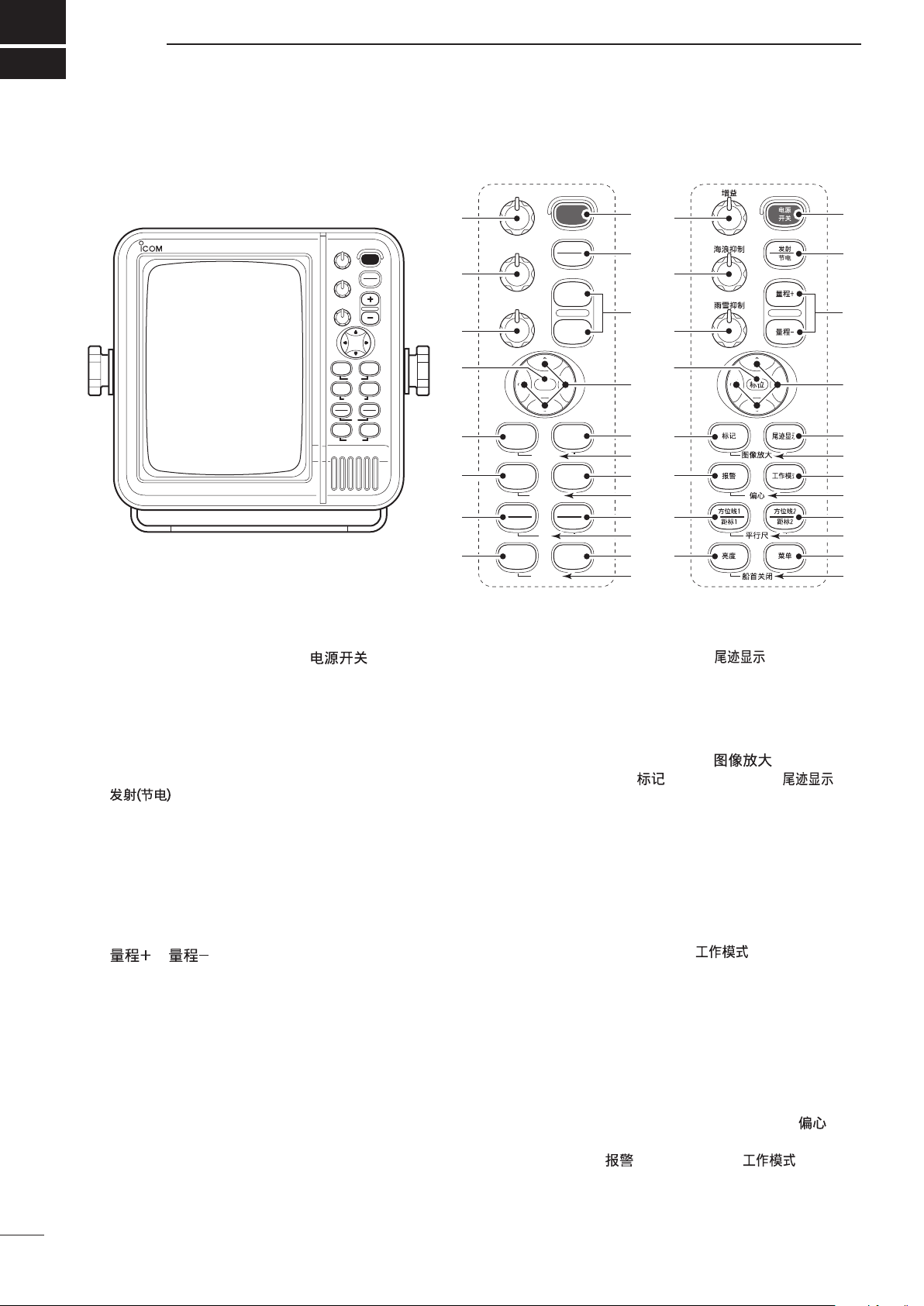
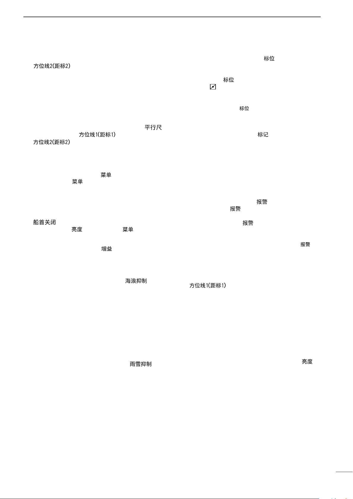
1 PANEL DESCRIPTION .................................. 1–4
■Front panel ...................................................... 1
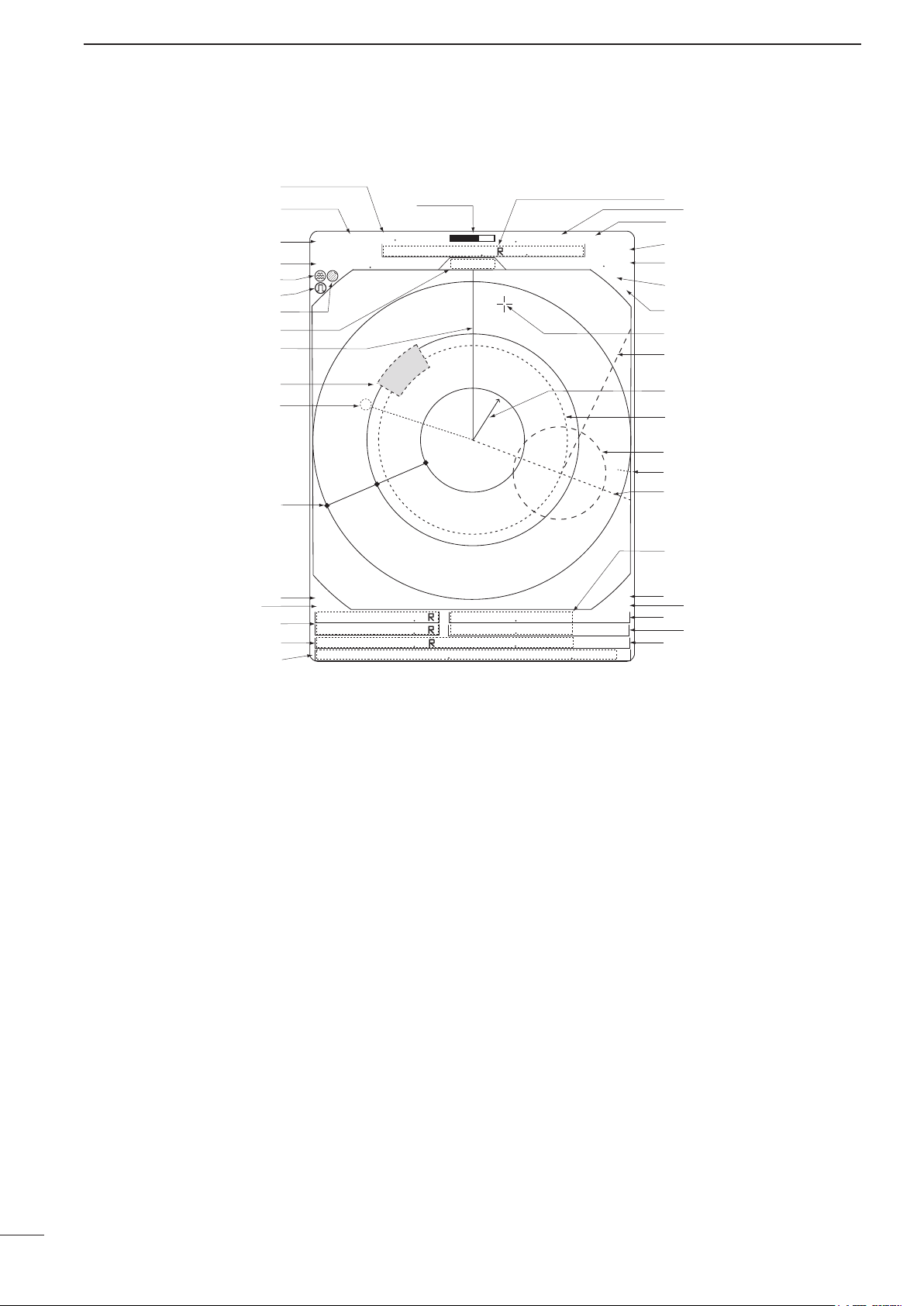
■Screen ............................................................ 3
2 MENU ............................................................. 5–6
■VIDEO ............................................................. 5
■FUNCTION ...................................................... 5
■ATA (Automatic Tracking Aid) ........................... 6
■INT. SETTING .................................................. 6
3 BASIC OPERATION .................................... 7–12
■Checking the installation ................................. 7
■Turning power ON/OFF.................................... 7
■Basic operation ............................................... 8
■RAIN function................................................... 9
■SEA function.................................................... 9
■OFF CENTER function .................................... 9
■IR function ..................................................... 10
■STRETCH function ....................................... 10
■ZOOM function ............................................. 10
■TRAILS function ............................................ 11
■Power save function ...................................... 11
■Ship speed indication .................................... 12
■Position indication ......................................... 12
■Waypoint indication........................................ 12
■Long pulse function........................................ 12
■Bearing setting .............................................. 12
4 DISTANCE AND DIRECTION
MEASUREMENTS ..................................... 13–15
■Distance measurement ................................. 13
■Bearing and Distance measurement ............ 14
■Advanced measurements ............................. 15
5 ALARM FUNCTION ......................................... 16
■Alarm zone setting ........................................ 16
■Zone alarm setting ........................................ 16
6 ATA (Automatic Tracking Aid) .................. 17–19
■ATA (Automatic Tracking Aid) ........................ 17
■ATA menu setting .......................................... 17
■ATA operation ................................................ 18
■Plotting marks ............................................... 18
■Course and speed vector .............................. 18
■Plots .............................................................. 19
7 BASIC RADAR THEORY .......................... 20– 22
■Side-lobe echoes .......................................... 20
■Indirect echoes ............................................. 20
■Multiple echoes ............................................. 21
■Minimum range ............................................. 21
■Blind and Shadow sectors ............................ 22
■Target resolution ............................................ 22
8 INSTALLATION AND CONNECTIONS ..... 23–29
■Connecting the units ..................................... 23
■Power source requirement ............................ 23
■Ground connection ........................................ 23
■Installing the display unit ............................... 24
■Mounting the EX-2714 scanner unit ............. 25
■Wiring the EX-2714 system cable ................. 26
■Mounting the EX-2780 scanner unit ............. 27
■Wiring the EX-2780 system cable ................. 28
■Attaching the EX-2780 scanner unit ............. 29
9 OTHER FUNCTIONS ....................................... 30
10 SERVICE MAN MENU ............................... 31–33
■Service man menu ........................................ 31
■Select the language ...................................... 31
■TIMING adjustment ....................................... 32
■HDG adjustment ............................................ 32
■SPD adjustment............................................. 33
■RANGE selection........................................... 33
11 ERROR MESSAGE .......................................... 34
■Error message list ......................................... 34
12 MAINTENANCE................................................ 35
■Periodic maintenance ................................... 35
■Scanner unit maintenance ............................ 35
■Display unit maintenance .............................. 35
■Options ......................................................... 35
13 SPECIFICATIONS ...................................... 36–37
14 EXTERNAL DATA LIST ................................... 38
(Supplement) TEMPLATE
■Template for the display unit
• SX-2713/SX-2779
(Display mount bracket template)
■Template for the scanner unit
• EX-2714
• EX-2780
TABLE OF CONTENTS

1
PANEL DESCRIPTION
1
■Front panel
qPOWER SWITCH [POWER]/[ ] (p. 7)
Push to turn the radar power ON or OFF.
• The standby screen appears for 90 seconds while the
magnetron warms up.
• The initial screen appears and a beep sounds after the
power has been turned ON.
wTRANSMIT/SAVE SWITCH [TX (SAVE)]/
[ ]
➥Push to toggle between the TX mode and the
standby mode. (p. 8)
➥Hold down for 1 second to turn ON the power
save function. The radar for TX interval scan is
fixed at 10 revolutions. (p. 11)
• Select the save time in INT. SETTING menu.
eRANGE UP/ DOWN SWITCHES [+]/[–]/
[ ]/[ ] (p. 8)
Push [+] to increase the screen range.
Push [–] to decrease the screen range.
rUP, DOWN, LEFT, RIGHT KEYS [p] [q] [t] [u]
Set the EBLs, VRMs, alarm area, ATA target, etc.
according to the key pushed.
Use [p] [q] to select menu item and [t] [u] to set
the item.
Using [p] [t]/[p] [u] or [q] [t]/[q] [u] combina-
tion allows you to move the cross line cursor to the
upper (or lower) left or right.
tTRAILS SWITCH [TRAILS]/[ ] (p. 11)
Push to toggle the trail function ON or OFF. This is
useful for watching other ship’s tracks, approximate
relative speed.
• Trail Time can be set in VIDEO menu.
yZOOM FUNCTION [ZOOM]/[ ] (p. 10)
Push [TARGET]/[ ] and [TRAILS]/[ ] si-
multaneously to toggle the ZOOM function ON or
OFF. The ZOOM function enlarges the target to two
times normal size.
• Move the cursor to the target, then turn ON the function.
• The screen zooms the middle of the screen around own
ship.
• This function is not available on the 1⁄8and the 32 NM or
higher ranges.
uMODE SWITCH [MODE]/[ ]
Push to select the Head-up (H UP), Course-up (C
UP), North-up (N UP) or True motion (TM) screens.
• The North-up and Course-up screens can be selected
only when a bearing data input is connected. (p. 38)
• The TM screen requires bearing data and LOG or posi-
tion data. (p. 38)
• TheTM screen is not selectable on the 32 NM or higher
range.
iOFF CENTER FUNCTION [OFF CENT]/[ ]
(p. 9)
Push [ALM]/[ ] and [MODE]/[ ] simulta-
neously to turn the OFF CENTER function ON or
OFF.
• This function is usable on 24NM or less ranges.
MOB
GAIN
SEA
RAIN
POWER
TX
SAVE
TARGET
TRAILS
ZOOM
ALM
MODE
OFF CENT
EBL1
VRM1
PI
BRILL MENU
HL OFF
EBL2
VRM2
MARINE RADAR
TX
SAVE
TARGET TRAILS
MODEALM
+
-
MOB
MENU
EBL2
VRM2
EBL1
VRM1
BRILL
ZOOM
OFF CENT
PI
HL OFF
GAIN
SEA
RAIN
POWER
e
r
q
w
t
u
o
!1
y
i
!2
!3
!4
!5
!6
!7
!8
!9
@0
e
r
q
w
t
u
o
!1
y
i
!2
!3
!4
!5
!6
!7
!8
!9
@0
!0 !0
Control panel (English) Control panel (Chinese)

2
1
PANEL DESCRIPTION
oEBL2 (VRM2) SWITCH [EBL2 (VRM2)]/
[] (pp. 14, 15)
Push to display the electronic bearing line 2 (EBL2)
and the variable range marker 2 (VRM2), and acti-
vate the [t] [u] for the electronic bearing line se-
lector and [p] [q] for the range marker selector.
• When VRM1 and EBL1 ($9 %2) are displayed, the center
of VRM2 appears at the intersection point of VRM1 and
EBL1.
!0 PARALLEL INDEX LINE FUNCTION [PI]/[ ]
Push [EBL1]/[ ] and [EBL2]/
[ ] simultaneously to toggle the paral-
lel index line ON and OFF.
• Push [t] [u] to rotate the lines, and push [p] [q] to
adjust the line spaces.
!1 MENU SWITCH [MENU]/[ ] (pp. 5, 6)
Push [MENU]/[ ] to toggle the VIDEO, FUNC-
TION, ATA, INT. SETTING and SERVICE MAN
menus. Push [p] [q] to select the items and push
[t] [u] to change the setting.
!2 HEADING LINE OFF FUNCTION [HL OFF]/
[] (p. 8)
Push [BRILL]/[ ] and [MENU]/[ ] simultane-
ously to turn OFF the heading line temporarily.
!3 GAIN CONTROL [GAIN]/[ ](p. 8)
Adjusts the receiver amplifier gain.
• Clockwise rotation increases the gain.
• Increased gain may increase screen noise.
!4 SEA CLUTTER CONTROL [SEA]/[ ] (p. 9)
This function serves to eliminate echoes from the
waves at close range.
Reduces the receiver gain for close objects within a
radius of 8 nautical miles (approximately) to elimi-
nate sea clutter.
Rotate the control fully clockwise to activate the au-
tomatic SEA control function. SEA indicator (@6) ap-
pears in the upper left of the screen.
• Under normal conditions set the SEA to a minimum.
• Use this control with caution when the sea is rough.
!5 RAIN CLUTTER CONTROL [RAIN]/[ ]
(p. 9)
This function eliminates echoes from rain, snow,
fog, etc.
Rotate the control fully counter clockwise to deacti-
vate the RAIN function.
RAIN indicator (@8) disappears.
!6 MAN OVERBOARD [MOB]/[ ]
Push to mark the man overboard point on the
screen. When a crew member falls overboard, hold
down [MOB]/[ ] for 1 second to display the MOB
symbol ( ) on the screen.
• The MOB readout shows the bearing, distance and es-
timated time to the MOB point with current speed.
• Hold down [MOB]/[ ] for 1 second to cancel the
function.
• Position and bearing data are necessary.
!7 TARGET SWITCH [ATA]/[ ] (pp. 17–19)
A setup of target caught by ATA (up to 10 targets
can be set).
• Push [p] [q] [t] [u] to move the cross cursor on the
echo which you want to plot, before turning ON the func-
tion.
• Set the “ATA” function to ON in the “ATA” menu, then set
the appropriate No. DISP, VECT, OWN VECT, ALARM,
CPA LIMIT and TCPA LIMIT settings.
!8 ALARM SWITCH [ALM]/[ ] (p. 16)
➥Push [ALM]/[ ] to toggle the alarm function
ON and OFF.
➥Hold down [ALM]/[ ] for 1 second to enter the
alarm area setting condition.
• Push [p] [q] [t] [u] to move the cross cursor to the
zone starting point, then hold down [ALM]/[ ] for
1 second. The starting ring of the zone is created.
Then push [p] [q] [t] [u] to fix the finish point, and
the desired alarm zone will automatically form.
!9 EBL1 (VRM1) SWITCH [EBL1 (VRM1)]/
[ ] (pp. 14, 15)
Push to display the electronic bearing line 1 (EBL1)
and the variable range marker 1 (VRM1) and acti-
vate [t] [u] for the electronic bearing line selector,
and [p] [q] for the range marker selector.
• EBL1 bearing and VRM1 distance are displayed, in the
bottom window.
• When EBL1 and VRM1 are displayed, the beginning
of EBL2 appears at the intersection point of EBL1 and
VRM1.
@0 DISPLAY BRILLIANCE SWITCH [BRILL]/[ ]
(p. 8)
➥Push to increase or decrease the brilliance of the
picture on the display.
➥Hold down for 1 second to select the maximum
brilliance.
The brightness of the symbols, characters and il-
luminations can be independently adjusted in the
“SYMBOL”, “CHARACTER” and “KEY ILLUM” of the
INT. SETTING menu.

3
1PANEL DESCRIPTION
@1 TUNING LEVEL INDICATOR (p. 8)
Shows the receiver tuning level.
@2 TUNING MODE INDICATOR (p. 8)
“M.TUNE” appears when the manual tuning func-
tion is in use.
@3 FIXED RING RANGE READOUT (p. 13)
Shows the interval range of the fixed ring.
• This readout appears when “RING” in the FUNCTION
menu is turned ON.
@4 SCREEN RANGE READOUT (p. 13)
Shows the maximum range of the displayed screen.
• The range indicated is nautical miles (NM).
@5 SHIP SPEED READOUT (p. 12)
Shows the ship speed.
• SOG: When GPS is selected in the INT. SETTING
menu.
• STW: When LOG is selected in the INT. SETTING
menu.
@6 AUTO SEA INDICATOR (p. 9)
Appears when the automatic SEA control function
is turned ON.
@7 LONG PULSE INDICATOR (p. 12)
Appears when the long pulse is in use.
@8 RAIN CONTROL INDICATOR (p. 9)
Appears when the RAIN function is in use.
@9 MODE INDICATOR
Head-up, Course-up, North-up and True Motion
screens are available.
• N UP and C UP screens require external bearing data.
(p. 38)
• TM screen requires bearing data and LOG or position
data.
#0 HEADING LINE (p. 8)
Heading line indicates the ships bow direction.
#1 ALARM ZONE (p. 16)
Shows the alarm zone.
•Appears when the alarm function is in use.
#2 WAYPOINT MARKER (p. 12)
Shows the waypoint received from navigation equip-
ment.
• This marker appears when “WPT” in the FUNCTION
menu is turned ON.
• To display the waypoint marker, bearing data and
NMEA data in 0183 format is necessary. (p. 38)
#3 FIXED RANGE RINGS (p. 13)
Shows the distance in fixed intervals. The interval
distance is indicated by the ring range readout (@3).
• These rings appear when “RING” in the FUNCTION
menu is turned ON.
#4 GPS INDICATOR (p. 23)
Indicator appears when the GPS or DGPS receiver
is connected.
:
:
:
:
(0.25)
MTUNE
TVECT
6M
0649NM
NM
CURS
STW
157
KT H UP
0174
˚
R
TRAILS
HDG2530
˚T
IR
EBL1
EBL2
WPT
VRM1
VRM2
CURS
1076
˚
0219
˚
2834
˚
0422
NM
001
000
001
0242
NM
0632
NM
34
˚
39720N 135
˚
34420E
ZOOM
ALM
COMPASS
GPS
ES
005
3/4
@1
@2
@3
@4
@5
@6
@7
@8
@9
#0
#1
#2
#3
#4
#5
#6
#7
#8
#9 $0
$1
$2
$3
$4
$5
$6
$7
$8
$9
%0
%1
%2
%3
%4 %5
%6 %7
%8
■Screen

4
1
PANEL DESCRIPTION
#5 COMPASS INDICATOR (pp. 23, 38)
• GYRO : NMEA (gyro) is connected.
• COMPASS : NMEA (compass), N+1 or AUX data is
connected.
#6 EBL1/ 2 READOUTS (pp. 14, 15)
Shows the bearing of the displayed Electronic Bear-
ing Lines (EBL1 and EBL2) when EBL is in use.
EBL2 shows PI (!0) readout.
#7 WAYPOINT/MOB READOUTS (p. 12)
➥Shows the bearing and distance to the waypoint
received from navigation equipment.
• This readout appears when “WPT” in the FUNCTION
menu is turned ON.
• To display the waypoint/MOB marker, bearing data
and NMEA data in 0183 format is necessary. (p. 38)
➥Shows the bearing and distance to the MOB
(Man Over Board) event marker.
• Push [MOB]/[ ] to cancel the readout and the
symbol.
#8 POSITION/CURSOR READOUT (p. 12)
Shows your own ship or cursor latitude and longi-
tude readout when external NMEA data in 0183 for-
mat is connected.
• Select ‘SHIP’ or ‘CURS’ in the “POSN DISP” item of the
FUNCTION menu.
• To display the POSITION; NMEA 0183 is necessary.
• To display the CURSOR; NMEA 0183 and bearing data
are necessary.
#9 CURSOR INDICATOR
Shows the bearing and distance to the cursor.
$0 VECTOR INDICATOR (p. 17)
Shows the ATA and OWN vector type.
• T : True vector
• R : Relative vector
$1 VECTOR TIME INDICATOR (p. 17)
Shows the vector interval time. Select vector time in
the “TRAIL TIME” of the VIDEO menu.
• 30 minutes is applied, when ‘∞’ is selected for the vec-
tor time.
$2 TRAILS INDICATOR (p. 11)
Shows the trail time.
• Echo remains with gradation during the trail time period
on the screen. (Except for the trail time; ∞)
• Progressing time counter starts to count the time until
the timer reaches the trail time.
$3 HEADING INDICATOR
Shows the heading bearing readout.
• The HDG readout indicates the bow of the ship’s bear-
ing in a clockwise direction from north.
$4 IR INDICATOR (p. 10)
Eliminates or reduces interference caused by other
radar operating nearby.
• This function is available when the “IR” in the VIDEO
menu is set to 1 or 2.
$5 ECHO STRETCH INDICATOR (p. 5)
Appears when the echo stretch function is in use.
• This function is available when “STRETCH” in the
VIDEO menu is turned ON.
$6 CROSS LINE CURSOR
Used for measuring the bearing and distance, set-
ting the alarm zone, selecting the ATA targets, etc.
• Push [p] [q] [t] [u] one or more times to move the
cursor.
$7 EBL2 (pp. 14, 15)
Used for bearing measurement. When a target is
selected, the EBL readout (#6) shows the bearing.
$8 OWN SHIP VECTOR INDICATOR
Shows the vector of your own ship.
$9 VRM 1 (pp. 14, 15)
%0 VRM 2 (pp. 14, 15)
Used for distance measurement. When a target is
selected, the VRM1/2 readout (%3) shows the dis-
tance.
%1 NORTH MARK
The north mark shows the true north direction.
%2 EBL1 (pp. 14, 15)
Used for bearing measurement. When a target is
selected, the EBL readout (#6) shows the bearing.
%3 VRM1/2 READOUTS (pp. 14, 15)
Shows the distance of the displayed Variable Range
Markers (VRM1 and VRM2) when the VRM is in
use.
• Nautical miles (NM) and kilometers (KM) can be se-
lected in the FUNCTION menu as the distance unit.
%4 ALARM INDICATOR (p. 16)
Appears when the alarm function is in use.
%5 ZOOM INDICATOR (p. 10)
Appears when the zoom function is in use.
• Push [TARGET]/[ ] and [TRAILS]/[ ] simul-
taneously to turn the function ON or OFF.
%6 TIME INDICATOR
%7 TIME INDICATOR
Shows the estimated time to the marker edge from
the center of the marker, at the current speed.
%8 TIME INDICATOR
Shows the estimated time to the waypoint at the
current speed.

2
5
MENU
■VIDEO
VIDEO MENU
D.RANGE
IR
STRETCH
PULSE
SEA
TRAIL TIME
ON
12
LP
MANUAL
AUTO
MID. WIDE
OFF
OFF
SP
6S
3M
15S
6M
30S
15M
1M
TUNE
1234
NAR.
DTUNE
• AUTO : Automatic tuning.
• “A.TUNE” appears for approximately 2 sec-
onds, instead of the screen display, when
first transmitting after turning ON the power.
The unit also retunes in some cases.
• MANUAL : Manual tuning.
Push [u] to select [MANUAL] then push
[q] to activate the manual tuning slider.
Push [t] [u] to adjust the desired tuning
level.
DD.RANGE
Select the dynamic range of the PPI (Plan Position In-
dicator).
• NAR. : Narrow dynamic range. Even weak reec-
tions are displayed as strong reections.
• MID. : Mid dynamic range.
• WIDE : Wide dynamic range. You can easily dis-
tinguish between weak reflections and
strong reections.
DIR
• OFF : Turn OFF the Interference Reduction
function.
•
1 or 2 (ON)
: Turn ON the Interference Reduction func-
tion 1 (Low) or 2 (High).
DSTRETCH
• OFF : Turn OFF the echo stretch function.
• ON : Turn ON the echo stretch function.
DPULSE
• SP : Select the short pulse.
• LP : Select the long pulse. LP indicator ap-
pears on the screen.
DSEA
• The characteristic (curve) of a SEA knob can be cho-
sen as the optimal characteristic out of four kinds with
the height of an antenna.
DTRAIL TIME
• 6S,15S, 30S, 1M, 3M, 6M, 15M or ∞:
Select the plot interval and vector time.
■FUNCTION
FUNCTIONMENU
POSN DISP
WPT ON
DIST UNIT
BRG
EBL/PI
ZONE ALARM
BEEP
MAG
PT/SB
KM
OUT
ON
OFF
CURS
NM
TRUE
TRUE
IN
RING
OFF ON
OFF
SHIP
360˚R
DRING
• OFF : Turn OFF the xed range ring display.
• ON : Turn ON the xed range ring display.
DWPT
• OFF : Do not display the waypoint on the screen.
• ON : Display the waypoint on the screen.
DPOSN DISP
• SHIP : Display your own ship’s position.*1
• CURS : Display the cursor position.*2
*1External latitude/longitude data required.
*2External latitude/longitude data and bearing data re-
quired.
DDIST UNIT
• NM : Display the distance unit in Nautical Miles.
• KM : Display the distance unit in Kilometers.
DBRG
Select the displayed bearing type, no relation with the
bearing data format (NMEA, N+1 or AUX).
• TRUE : Select the true North bearing.
• MAG : Select the magnetic North bearing.
DEBL/PI (except HDG and CSE) (p. 14)
• TRUE : True or magnetic direction.
• 360°R : Relative direction
• PT/SB : Bow direction
DZONE ALARM
• IN : An alarm sounds when the target comes
into the zone.
• OUT : An alarm sounds when the target goes out
of the zone.
DBEEP
• OFF : Turn OFF* the beep tone.
• ON : Turn ON the beep tone.
* Except for the alarm function.

6
2
MENU
■ATA (Automatic Tracking Aid)
ATA MENU
VECT
No.DISP OFF ALL
OWN VECT
ALARM
CPA LIMIT
TCPA LIMIT
TRUE
ON
ON
ON
OFF
REL
OFF
OFF
1.0NM
1 MIN
ATA
SEL
DATA
• OFF : Turn OFF the ATA function.
• ON : Turn ON the ATA function.
DNo.DISP
• OFF : Do not display any mark number.
• Sel : Display the selected mark number
only.
• ALL : Display all mark numbers.
DVECT
• TRUE : Select the true vector mode.
• REL : Select the relative vector mode.
DOWN VECT
• OFF : Do not display your own ship’s vec-
tor.
• ON : Display your own ship’s vector.
DALARM (CPA/TCPA)
• OFF : Turn OFF the alarm function.
• ON : Turn ON the alarm function.
DCPA* LIMIT
• 0.1 to 10.0NM : Set the CPA (Closest Point of Ap-
proach) limit with [t] [u].
DTCPA* LIMIT
• 1 to 60MIN : Set the TCPA (Time to CPA) limit time
with [t] [u].
*CPA/TCPA: Closest Point of Approach and Time to Closest
Point of Approach limit is defined by the observer to given
warning when a target or targets are close to within those
limits from your own ship.
■INT. SETTING
INT. SETTING
BRG INPUT
SPD INPUT
TX INH START
TX INH ANGLE
SAVE TIME
SYMBOL
CHARACTER BRILL
NMEA
30M
LOG
6M 15M
MANUAL
AUTO
N+1 AUX GPS
GPS
0
˚
0
˚
KEY ILLUM
MAG VAR
123
123
1234
7.2
˚
W
1M
DMAG VAR
• AUTO : Automatically revise magnetic variations.
NOTE: NMEA data is required. NEVER select
“AUTO” without NMEA data; incorrect varia-
tion data may entered. (p. 38)
• MANUAL : Revise magnetic variation manually.
• Push [u] to select [MANUAL], then push [q].
Set the revised value with [t] [u]. Push [q]
or [MENU] to exit the menu.
DBRG INPUT
• NMEA : NMEA0183 bearing data format.
• N+1 : N+1 data format.
• AUX : Other format.
• GPS : Reads NMEA0183 COG format data as
HDG format.
DSPD INPUT
• GPS : Use the GPS NMEA speed data.
• LOG : Use the speed sensor data.
DTX INH START
• 0 to 359° : Push [t] [u] to enter the start point of
the TX inhibit area.
DTX INH ANGLE
• 0 to 90° : Push [t] [u] to enter the TX inhibit area.
DSAVE TIME
• 1M, 6M, 15M or 30M
: Select the standby time during the save
mode.
• The radar for TX interval scan is xed at 10
revolutions.
DSYMBOL
• 1/2/3 : Select the symbol brightness.
DCHARACTER
• 1/2/3 : Select the character brightness.
DKEY ILLUM
• 1/2/3/4 : Select the key illumination brightness.

BASIC OPERATION
3
7
■Checking the installation
Before turning ON the power, be sure all the connec-
tions are complete. The checklist at right may be help-
ful for necessary confirmation.
CAUTION: Connect the scanner unit before turning ON
the power. Otherwise the magnetron inside the scanner
unit might be damaged.
DChecklist
qThe four bolts securing the scanner unit must be
firmly tightened.
wCabling must be securely attached to a mast or
mounting material, and must not interfere with the
rigging.
eBe sure waterproofing procedures are completed
on the system cable.
rThe power connections to the battery must be of
the correct polarity.
tBe sure that the plugs at the rear of the display unit
have been connected correctly and securely.
(See page 23 for details.)
■Turning power ON/OFF
1
(0.25)
T.VECT 6M
0.000NM
NM CURS
SOG17.7KT H UP
000.0˚T
HDG253.4˚T
EBL1
EBL2
MOB
VRM1
VRM2
CURS 34˚ 37.72N 13 5˚34.42E
STBY
IR
COMPASS
GPS
1
(0.25)
T.VECT 6M
0.000NM
NM CURS
SOG17.7KT H UP
000.0˚T
HDG253.4˚T
EBL1
EBL2
MOB
VRM1
VRM2
CURS 34˚ 37.72N 13 5˚34.42E
IR
COMPASS
GPS
0.45
REV *.*
ROM OK
RAM OK
qPush [POWER]/[ ] to turn ON the power.
• The initial screen appears and the magnetron warm up
time is counted down on the screen.
•
The magnetron inside the scanner unit warms up for 90
seconds.
• [POWER]/[ ] is disabled for 2 seconds after
the power is turned OFF.
wWhen the countdown is completed, the Standby
screen appears.
ePush [TX]/[ ] to start scanning and select
the Plan Position Indicator (PPI) screen.
• Targets and heading markers appear.
• The screen appears approximately 2 seconds after
turning ON the power, when ‘AUTO’ is selected in the
“TUNE” item of the VIDEO menu.
rPush [POWER]/[ ] to turn OFF the power.

3
BASIC OPERATION
8
■Basic operation
TX
SAVE
TARGET TRAILS
MODEALM
+
-
MOB
MENU
EBL2
VRM2
EBL1
VRM1
BRILL
ZOOM
OFF CENT
PI
HL OFF
GAIN
SEA
RAIN
POWER
e
q
w
u
r
t
y
e
q
w
u
r
t
y
qTurn ON the power.
wPush [TX]/[ ] after the countdown disap-
pears from the screen.
• See “Turning power ON/OFF” on page at left.
ePush [+]/[ ] or [–]/[ ] one or more times
to select the display range.
• The screen range readout shows the maximum range
of the screen.
rRotate [GAIN]/[ ] to the 1 o’clock position.
• Clockwise rotation increases the gain.
• Increased gain may increase screen noise.
tRotate [SEA]/[ ] to set the sensitivity time
control to minimum.
yRotate [RAIN]/[ ] to set the rain clutter con-
trol to minimum.
uPush [MODE]/[ ] to select either the
Head-up; H UP, Course-up; C UP, North-up; N UP
or True Motion; TM screen.
C UP, N UP or TM can be selected only when
bearing, position or speed data is provided.
(See page 38 for details)
CAUTION: When setting the [SEA]/[ ] control to
a fully clockwise position, close targets are blanked.
DHeading marker
The heading marker is a line that shows your ship’s
bow direction. (This marker will appear in the cen-
ter of the screen when the Head-up screen H UP
is selected.) The heading marker can be hidden
when the desired target is located under the heading
marker.
➥Simultaneously hold down [BRILL]/[ ] and
[MENU]/[ ] to hide the heading marker.
DFixed range rings
The fixed range rings can be used for rough distance
measurements. (p. 13)
➥Push [MENU]/[ ] to open the FUNCTION menu,
then push [q] to select RING. Push [u] to turn ON
the ring.
DManual tuning
The receiver tuning can be manually adjusted.
➥Push [MENU]/[ ] to open the VIDEO menu, then
select MANUAL. Push [q] to activate the manual
tuning slider, then push [t] [u] to set the tuning
level indicator to the maximum level. (p. 5)
• “M.TUNE” appears at the top of the display.
DBrilliance adjustment
The intensity of the screen can be adjusted. When
you require continuous operation, but not constant
viewing, a lower setting can increase the life of the
CRT display.
➥Push [BRILL]/[ ] to increase or decrease the bril-
liance of the picture on the display.
➥Hold down [BRILL]/[ ] for 1 second to select max-
imum brilliance.
NOTE: High intensity will shorten the life of the CRT
display.
• Key illumination
The backlighting of the keys can be adjusted for con-
venient operation. (p. 6)
➥Push [MENU]/[ ] four times to call up the INT.
SETTING menu. Push [t] [u] to select the illumi-
nation level.
• Key illumination corresponds with [BRILL]/[ ] con-
trol.
NOTE:
Manual adjustment can be used. (See below.)

9
3BASIC OPERATION
The following are typical basic operation examples, which may hinder radar reception (sea clutter, precipitation
interference and echoes from other radar).
■RAIN function
Adjust RAIN control
Small echos
This function eliminates echoes from rain, snow, fog
etc.
• Rotate the control fully counterclockwise to deactivate the
control function. The RAIN indicator ( ) disappears.
• NOTE: DO NOT reduce the echoes too much, otherwise
you may miss weaker targets.
■SEA function
Adjust SEA control
Echos from sea waves
This function serves to eliminate echoes from waves at
close range. Reduce the receiver gain for close objects
within a radius of 8 miles to eliminate sea clutter.
• Rotate the control fully clockwise to activate the automatic
control function. SEA indicator ( ) appears in the upper
left corner of the screen.
■OFF CENTER function
With OFF CENTER ON
Normal screen
The scanning area can be shifted in a desired direction
and can be partially enlarged. This is useful when
Head-up* screen is selected, and you want to enlarge
the bow direction display, or the center of the screen
shifts in the direction of the intersection.
• This function is selectable for 24NM or shorter ranges.
*This function is not selectable in the TM screen.
qPush [p] [q] [t] [u] to move the cursor where
you want to shift the center of the screen.
• Max. offsetting is up to 75% of the screen.
wPush [ALM]/[ ] and [MODE]/[ ] simulta-
neously to shift the screen.
ePush [ALM]/[ ] and [MODE]/[ ] simulta-
neously again to return to the normal screen.
WARNING: The [SEA]/[ ] control re-
duces the receiver sensitivity of objects within 8
miles. Therefore, caution and careful adjustment are
necessary when using the [SEA]/[ ] control.
Small objects may not be displayed on the screen
when strong echoes from rain or islands within 1 NM
while the automatic SEA function is activated.

10
3
BASIC OPERATION
■IR function
With IR function ON
Radar interference
Radar interference may appear when another ship’s
radar is operating on the same frequency band in
close proximity. The IR function can eliminate this type
of interference. (p. 5)
qPush [MENU]/[ ] to call up VIDEO menu.
wHold down [q] until the “IR” section becomes high-
lighted.
ePush [t] [u] to select IR function 1, 2 or OFF.
• “IR” appears in the upper right of the screen, when the
function is activated.
■STRETCH function
With STRETCH ON
Normal screen
The blips can be magnified electronically for easier
viewing of small targets. (p. 5)
qPush [MENU]/[ ] to open the VIDEO menu.
wPush [q] to select “STRETCH”, then push [u] to
turn ON the function.
NOTE: Turn OFF this function during normal opera-
tion.
■ZOOM function
With ZOOM function ON
Normal screen
The ZOOM function expands the target to two times
normal size.
• This function is selectable up to a 24 NM range or shorter
except 1⁄8NM.
qPush [p] [q] [t] [u] to move the cursor to the
desired target.
wPush [TARGET]/[ ] and [TRAILS]/[ ]
simultaneously to toggle the ZOOM function ON
and OFF.
• “ZOOM” appears in the lower right of the screen.

11
3BASIC OPERATION
■TRAILS function
The trails function memorizes echoes continuously or
at constant intervals. This is useful for watching other
ships’ tracks, approximately relative speed, etc.
3/4
(0.25)
M.TUNE 1:0 5
NM CURS
STW 15.7KT H UP HDG 253.9˚T
6M
TRAILS
IR
ES
T.VECT
0.453NM
TRAIL
indicator
Trail interval
counter
Trail time
Trail time
• Setting the trail interval time
qPush [MENU]/[ ] to call up the VIDEO menu.
• Push [q] one or more times until the “TRAIL TIME” sec-
tion becomes highlighted.
wPush [t] [u] to select trail interval time.
• 6 seconds, 15 seconds, 30 seconds, 1 minute, 3 min-
utes, 6 minutes, 15 minutes and ∞(continuous) are se-
lectable.
ePush [MENU] one or more times to exit the menu.
• Using the TRAILS function
qPush [TRAILS]/[ ] to turn ON the trail func-
tion.
• “TRAILS” and trail interval time appears in the upper
right of the screen.
• Trail interval counter starts to count up to the trail time.
wAll displayed echoes at the plotted time are mem-
orized and displayed with a graduated intensity
together with the current echoes.
• Echoes are displayed with minimum intensity when “∞”
is selected.
ePush [TRAILS]/[ ] to cancel the trail function
and erase the plotted echoes.
• “TRAILS” and trail interval time disappears.
■Power save function
The power save function conserves the boat’s battery
power by pausing the transmission. The standby
(pausing) times are selectable (rotation number is
fixed to 10).
For example, when 1 minute is selected, the scanner
rotates 10 revolutions; then stops for 1 minute, and
then repeats this sequence while the power save func-
tion is activated.
CURS 34˚ 37.72N CURS 34˚ 37.72N
1
(0.25)
T.VECT 6M
0.900NM
NM CURS
SOG17.7KT H UP
014.6˚T
HDG273.9˚T
IR
ES
EBL1
EBL2
MOB
VRM1
VRM2
13 5˚34.42E
0:48
SAVE
Hold down [TX] for 1 second
to turn the SAVE function on.
Scan and STBY alternates
Count down the standby time
1
(0.25)
T.VECT 6M
0.900NM
NM CURS
SOG17.7KT H UP
014.6˚T
HDG273.9˚T
IR
ES
EBL1
EBL2
MOB
VRM1
VRM2
13 5˚34.42E
0:00
SAVE
COMPASS
GPS
COMPASS
GPS
DSetting the scanning standby time
qPush [MENU]/[ ] four times to call up the INT.
SETTING menu.
wHold down [q] until the “SAVE TIME” section
becomes highlighted.
ePush [t] [u] to select standby time.
• 1, 6, 15, and 30 minutes are selectable.
rPush [MENU]/[ ] twice to exit the menu display.
DUsing the power save function
qHold down [TX (SAVE)]/[ ] for 1 second to
turn ON the power save function.
• The save indicator appears in the top of the screen.
wAfter the scanning rotations are finished, transmis-
sion and rotation are suspended until the selected
standby time elapses.
• The display shows the last scanned echoes until the
scanning restarts.
• “SAVE” and standby time appear in the top of the screen
and the standby time is counted down.
eAfter the selected standby time elapses, transmis-
sion and rotation restart.
rPush [TX (SAVE)]/[ ] to cancel the power
save function.
• The save indicator turns OFF.
NOTE: When you use the power save function
together with the alarm function, the CRT display is
turned OFF until an object enters the programmed
alarm zone, therefore, more power saving is
possible. (p. 16)

12
3
BASIC OPERATION
■Ship speed indication
When the ship speed data in NMEA 0183 format is ap-
plied, the radar can display the ship speed. Knots (KT)
or kilometers/hour (KM/h) are automatically selected
in the normal screen (p. 3) by selecting nautical miles
(NM) or kilometers (KM) respectively.
qPush [MENU]/[ ] one or more times to call up
the FUNCTION menu.
wHold down [q] until the “DIST UNIT” section
becomes highlighted.
ePush [t] [u] to select the ship speed indication to
NM or KM.
rPush [MENU]/[ ] one or more times to exit the
menu display or push [q] once to proceed to the
position display setting.
■Position indication
When latitude/longitude data in NMEA 0183 format is
applied, the radar can display the latitude and longi-
tude of your ship’s or cursor position in the bottom of
the display. (To display the CURSOR position, bearing
data is necessary.) (p. 38)
qPush [MENU]/[ ] one or more times to call up
the FUNCTION menu.
wHold down [q] until “POSN DISP” section becomes
highlighted.
ePush [t] [u] to select the ship position or cursor
position.
rPush [MENU] one or more times to exit the menu.
■ Waypoint indication
When waypoint data received from navigation equip-
ment in NMEA 0183 format is applied, the radar can
display the waypoint. To display the waypoint marker,
bearing data is necessary. (p. 38)
qPush [MENU]/[ ] one or more times to call up
the FUNCTION menu.
wHold down [q] until the “WPT” section becomes
highlighted.
ePush [t] [u] to turn the waypoint icon ON or OFF.
rPush [MENU]/[ ] one or more times to exit the
menu display.
■Long pulse function
To magnify the blips for easier viewing of small tar-
gets, the long pulse and echo stretch (p. 10) functions
are usable. When the long pulse is used in the 3⁄4to 2
NM range, this function magnifies target echoes to the
backward direction of the target.
• Pulse selection
qPush [MENU]/[ ] one or more times to call up
the VIDEO menu. (p. 5)
wHold down [q] until the “PULSE” section becomes
highlighted.
ePush [t] [u] to select SP (Short Pulse) or LP
(Long Pulse).
• When “LP” is selected, “ ” appears in the upper left of
the screen.
rPush [MENU]/[ ] one or more times to exit the
menu.
NOTE: To select SP (Short Pulse) reduces the
target distance resolution. (p. 22)
■Bearing setting
The radar bearing interface accepts NMEA, N+1 or
AUX data format and the bearing can use a magnetic
or true north type. When a true north type bearing is
used, the variation from magnetic north, etc., can be
adjusted on 0.1˚ steps.
DSetting the bearing type
qPush [MENU]/[ ] one or more times to call up
the FUNCTION menu.
wHold down [q] until the “BRG” section becomes
highlighted.
ePush [t] [u] to select magnetic or true north type.
• All displayed bearing readouts show the selected bear-
ing type.
DSetting the magnetic variation
qPush [MENU]/[ ] one or more times to call up
the INT. SETTING menu.
wHold down [q] until the “MAG VAR” sections be-
comes highlighted.
ePush [t] [u] to select an AUTO* or MANUAL varia-
tion.
rWhen a MANUAL variation is selected, push [q],
then push [t] [u] to set the bearing variation.
tPush [MENU]/[ ] to exit the menu display or
push [q] once to proceed to the bearing input set-
ting.
*NOTE: NMEA data is required for auto variation. NEVER
select “AUTO” variation without NMEA data, incorrect varia-
tion data may entered.

4DISTANCE AND DIRECTION MEASUREMENTS
13
■Distance measurement
Two measurement procedures can be used with this
radar. Use them separately or jointly is possible.
The distance unit, nautical miles (NM) or kilometers
(KM) is selected in the FUNCTION menu (p. 5).
DUsing the fixed rings
1
(0.25)
T.VECT
0.900NM
NM CURS
SOG 0.0KT H UP
014.6˚T
HDG
IR
ES
EBL1
EBL2
W
PT
VRM1
VRM2
CURS 34˚ 37.72N 13 5˚34.42E
Fixed ring
Ring range readout
qPush [MENU]/[ ] one or more times to call up the
FUNCTION menu.
wHold down [q] until the “RING” section becomes
highlighted.
ePush [u] to select RING function ON and display
the fixed ring.
• The interval range appears on the right of the screen
range readout.
• The ring range is xed depending on the screen range.
(See below.)
rPush [MENU]/[ ] one or more times to exit the
menu.
t To clear the fixed rings, push [t] to select OFF in
step eabove.
Range (nm)
Ring (nm)
1 1.5 23468121624323648*
1
⁄
81
⁄
41
⁄
23
⁄
4
255346 464646 46466
1122 44886
64
†
72
†
46
1216
1
⁄
20 1
⁄
20 1
⁄
10 1
⁄
41
⁄
41
⁄
41
⁄
21
⁄
2
NOTE: When the screen is shifted, the number of rings may differ.
*Available for the MR-1000TII/TIII.
†
Available for the MR-1000TIII only.
DUsing the variable range marker
q
Push [EBL1 (VRM1)]/[ ] to display VRM1
and EBL1; then push [p] or [q] to set the marker.
• The range between the ship and the target is indicated
in the VRM readouts.
w
Push [EBL2 (VRM2)]/[ ] to display VRM2
and EBL2; then push [p] or [q] to set the marker.
• The range between the ship and the target is indicated
in VRM readouts.
• When VRM1 and EBL1 are displayed, the center of
VRM2 appears at the intersection point of VRM1 and
EBL1.
• The VRM2 disappears when [EBL1 (VRM1)] is pushed.
ePush [EBL1 (VRM1)]/[ ] to exit the
menu display.
TYPE
RING
VRM1
VRM2
DESCRIPTION
Displays fixed rings.
Suitable for rough estimations from your
own ship to any target.
Displays a variable range marker and
activated by [p] [q] for the range
marker selector.
Suitable for accurate measurements
from your own ship to a target.
Normally functions the same as VRM1.
When the VRM1 and EBL1 selects a
target, the center of VRM2 appears at
the intersection point.
Suitable for accurate measurements
from target to target.

14
4
DISTANCE AND DIRECTION MEASUREMENTS
■Bearing and Distance measurement
This radar has two Electronic Bearing Lines (EBL) to
indicate the target direction from your ship or a target.
DUsing the EBL and VRM
3/4
TVECT 3M
1141NMNM CURS
SOG 00
km/h
H UP
3240
R
HDG
IR
3151
˚T
2471
˚T
WPT 34
0503NM
0359NM
EBL1
EBL2
VRM1
VRM2
POSN
EBL1
VRM1
EBL2
EBL1
readout
EBL2
readout
VRM2
VRM1 readout
VRM2 readout
qPush [p] [q] [t] [u] to move the cursor onto the
desired target.
wPush [EBL1 (VRM1)]/[ ] to display the
EBL1 and VRM1.
• Push [t] [u] to rotate the electronic bearing line.
• Push [u] to rotate clockwise and push [t] to rotate
counterclockwise.
• Push [p] [q] to increase or decrease the variable range
marker ring size.
• The EBL1 and VRM1 readouts indicate the target bear-
ing and distance.
• The EBL readouts indicate the target bearing;
0 to 360°R : Relative direction, when ‘360°R’ is se-
lected in the EBL/PI item of the FUNC-
TION menu. (See page 5)
P/S 0 to 180° : Bow direction, when ‘PT/SB’ is selected
in the EBL/PI item of the FUNCTION
menu. (See page 5)
0 to 360°T* : True or magnetic bearing, when select-
ing ‘TRUE’ in the EBL/PI item of the
FUNCTION menu. (See page 5)
*Bearing data is required. (p. 38)
ePush [EBL1 (VRM1)]/[ ] to clear EBL1
and VRM1.
• Cursor remains on the display.
rPush [p] [q] [t] [u] to move the cursor onto the
desired target.
tPush [EBL2 (VRM2)]/[ ] to display
EBL2 and VRM2 on the display.
• When EBL1 and VRM1 are displayed, the beginning
of EBL2 and VRM2 appears at the intersection point of
EBL1 and VRM1.
• EBL2 and VRM2 disappear when [EBL1 (VRM1)]/
[] is pushed.
yTo clear EBL1 and VRM1, push [EBL1 (VRM1)]/
[ ].

■Advanced measurements
Using both Electronic Bearing Lines (EBL) and both
Variable Range Markers (VRM), the following ad-
vanced measurements can be made:
DMeasuring the distance and direction between two targets
3/4
MTUNE TVECT 3M
1141NMNM CURS\
SOG
km/h
H UP
3171
˚M
HDG
IR
ES
EBL1
EBL2
WPT
VRM1
VRM2
3211
˚M
0890
˚T
0852NM
0814NM
POSN
ALM
GYRO
GPS
EBL2
EBL1
VRM2
VRM1
qPush [p] [q] [t] [u] to move the cursor onto the
desired target.
wPush [EBL1 (VRM1)]/[ ] to display the
EBL1 and VRM1.
•Push [t] [u] to rotate the electronic bearing line.
•Push [p] [q] to increase or decrease the variable range
marker ring size.
ePush [EBL2 (VRM2)]/[ ] to display the
EBL2 and VRM2.
• The intersection of the EBL1 and VRM1 becomes the
center of the EBL2 and VRM2.
rPush [p] [q] [t] [u] to move the cursor onto the
other target.
•Push [t] [u] to rotate the electronic bearing line.
•Push [p] [q] to increase or decrease the variable
range marker ring size.
tThe VRM2 readout shows the distance between
the two targets. The EBL2 readout shows the
direction from one target to the other.
DMeasuring the relative speed and course of a target
3/4
TVECT 6M
1141NMNM
CURS\
SOG KT H UP
3171
˚M
HDG
IR
ES
EBL1
EBL2
WPT
VRM1
VRM2
3211
˚T
1714
˚T
0401NM
0184NM
POSN
VRM2
EBL2
EBL1
VRM1
qPush [TRAILS]/[ ] (p. 11) to turn ON the
TRAILS function; then wait until the trail time count
up reaches to the TRAIL TIME.
wSet VRM1 and EBL1 to a previously plotted target
as described above.
eSet VRM2 and EBL2 to the current plotted position
of the same target, as described above.
rThe VRM2 readout is a measure of target move-
ment which can be converted into relative target
speed.
• For example, when a 6 minute trail time is selected,
multiplying the distance by ten gives the relative aver-
age speed of the target.
• If your ship is stationary during the plotting time, the
converted speed and direction become absolute.
• The converted speed unit is knots or kilometers/hour
when the selected unit in the FUNCTION menu is nau-
tical miles (NM) or kilometers (KM), respectively.
tThe EBL2 readout shows the course direction of
the target.
• Measuring the distance and course from a waypoint
qDisplay a waypoint. (See page 12)
wSet VRM1 and EBL1 to the displayed waypoint
targets as described above.
eSet VRM2 and EBL2 to a target (e.g. the next
waypoint) as described on page 14.
rThe VRM2 readout shows the distance to the
target from the waypoint.
• The distance unit can be selected as nautical miles
(NM) or kilometers (KM) in the FUNCTION menu.
tThe EBL2 readout shows the direction to the target
from the waypoint.
4DISTANCE AND DIRECTION MEASUREMENTS
15
Other manuals for MR-1000RII
2
This manual suits for next models
5
Table of contents
Other Icom Marine Radar manuals

Icom
Icom MXR-5000R User manual

Icom
Icom MR-1220 Series User manual

Icom
Icom MR-1200RII User manual

Icom
Icom MR-1210RII User manual

Icom
Icom MR-1000TIII User manual

Icom
Icom MR-570R User manual

Icom
Icom MR-1200TIII User manual

Icom
Icom MR-1000RII User manual

Icom
Icom MR-1000RII User manual

Icom
Icom MR-1200RII User manual